Table of Contents
Advertisement
Advertisement
Table of Contents

Related Manuals for Bay-Tek Skee Ball 1908 Alley


Summary of Contents for Bay-Tek Skee Ball 1908 Alley
-
Page 2: Factory Contact Information
FACTORY CONTACT INFORMATION BAY TEK ENTERTAINMENT Pulaski Industrial Park 1077 East Glenbrook Drive Pulaski, WI 54162 USA SIGN UP TO RECEIVE OUR E-MAILS! Stay up to date on the latest game information, new products launches, early notification of parts specials, updates of retro fit parts, software upgrades, best practices and more! Visit baytekent.com and enter your email to sign up! You can also register your new game at baytekent.com/register SALES... -
Page 3: Table Of Contents
TABLE OF CONTENTS FACTORY CONTACT INFORMATION ………………………….……. TABLE OF CONTENTS ……………… …………………………….…. WELCOME TO 1908 ALLEY ……………………………………..……. GAME SPECIFICATIONS ………………………………………….….. SAFETY PRECAUTIONS ………………………………………….…... GAME SET UP ………………………………………………………. 6 - 12 HOW TO PLAY ………………………………………………………….. 13 HOW TO ACCESS MAIN BOARD AND POWER SUPPLY ……… 14 HOW TO ACCESS BALL RELEASE ……………………...…….…... -
Page 4: Welcome To 1908 Alley
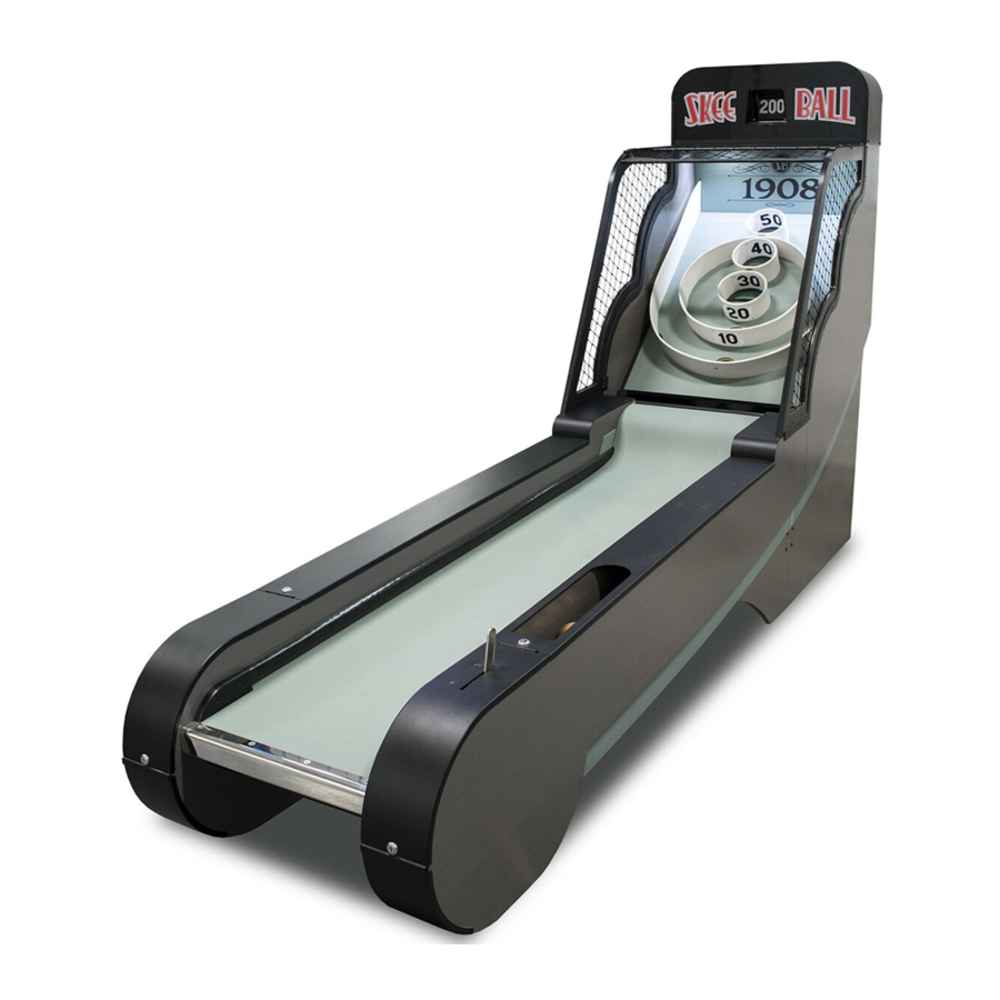
WELCOME TO 1908 ALLEY Congratulations on your 1908 Alley purchase! Skee-Ball has been entertaining audiences at boardwalks, fairs and entertainment centers for over 110 years, and now you can bring the nostalgia home! The 1908 Alley features all the fun of Skee-Ball –minus the coin slot—so you can keep the fun rolling! With a sleek design and simple-to-assemble cabinet, 1908 will complement any home game room Please take a moment to read through this manual as it contains a lot of helpful... -
Page 5: Game Specifications
GAME SPECIFICATIONS WEIGHT POWER REQUIREMENTS NET WEIGHT 485 lbs. 220 kg INPUT VOLTAGE 100 to 120 220 to 240 SHIP WEIGHT 540 lbs. 245 kg RANGE INPUT FREQUENCY GAME DIMENSIONS 50 Hz 60 Hz RANGE WIDTH 30.5” 77.5 cm DEPTH 123"... -
Page 6: Game Set Up
1908 ALLEY GAME SETUP The game will arrive on one pallet. Please inspect the pallet for shipping damage and report immediately to the freight company if any damage is found. Tools Needed: 9/16” Socket wrench Diagonal Cutting Pliers (Snips) 2 People A Phillips bit, # 2 Square bit, and 5/16”... - Page 7 1908 ALLEY GAME SETUP Remove the 2 shipping bolts underneath in the bottom of the ramp section using a 9/16” socket wrench. Carefully cut the plastic tie wrap holding cables using a side cutters (snips). Make sure not to cut the wire harness! Carefully remove alley section from pallet, lower it to the floor, this will be slid up to the target section after it is removed from the pallet.
- Page 8 1908 ALLEY GAME SETUP Remove the 2 shipping bolts underneath the target section using a 9/16” socket wrench. Carefully remove target section from pallet and place in final game position. Carefully move ramp section and place about 2 feet from target section. Align the Cables: At the back of the ramp section, push the AC power cable through the hole, then push the 4 signal cables through the...
- Page 9 1908 ALLEY GAME SETUP Position alley section closer to the target section as shown. Plug the 4 connectors together with the matching set of connectors. Push the connected plugs back into the target section of the game. The cables should be straight so they do not pinch as the sections are pushed together.
- Page 10 1908 ALLEY GAME SETUP Attach the Cages to the Game: Locate the side cages and unwrap from the bubble wrap. This assembly will be installed on the curved side of the target section. Press the side cages onto the curved side of the target section. There are pilot holes in the wood that must be aligned with the holes in the black plastic.
- Page 11 1908 ALLEY GAME SETUP Locate the large brackets inside the cabinet near the top of the side plastic assemblies. Locate the 4 black screws from hardware kit inside the cardboard box. Part # A5SCPH151 (#8 Square Drive) A5SCPH151 Install 2 screws into each side using the #2 square screwdriver bit.
- Page 12 1908 ALLEY GAME SETUP Install the front rod by pushing the rod through the gap in the front vinyl edge. Push it through so the rod protrudes out the opposite end. Locate 2 of the black machine Philips screws from hard- ware kit inside cardboard box.
-
Page 13: How To Play
HOW TO PLAY Turn the game on by flipping the power switch under the left front edge of alley. Flip this switch to the I symbol as shown. Pull the lever back to start a game. Roll the balls up the alley and into the targets to score points. -
Page 14: How To Access Main Board And Power Supply
HOW TO ACCESS MAIN BOARD & POWER SUPPLY Insert H95 key into left side rail cover, unlock, and slide cover toward you to remove. The main board, power supply, and cabling are now accessible. HOW TO ACCESS BALL RELEASE Insert H95 key into right side rail cover, unlock, and slide cover toward you to remove. -
Page 15: How To Access Target Sensors
HOW TO ACCESS TARGET SENSORS Reach under both bottom corners of the playfield and unlatch the 2 latches. Reach into a score hole to lift up on the playfield, slide it out and unplug the 2 cables behind. The ball sensors are attached to the back of the playfield. -
Page 16: How To Access Score Display Motor
HOW TO ACCESS SCORE DISPLAY MOTOR Unscrew the center knob on the marquee faceplate counter-clockwise and remove. Slide the marquee faceplate up to remove from game. Refer to trouble shooting section to diagnosis issues with the flip display. -
Page 17: Troubleshooting Guide
TROUBLESHOOTING GUIDE Problem Probable Cause Remedy Unplugged. Check wall outlet cable (AACE7213) to front of game under alley. Check power cables to power supply. No power to (AACE7220 & AACE7215) Rocker switch off or faulty. the game. Circuit breaker tripped. Check rocker switch located in front of game under alley. - Page 18 TROUBLESHOOTING GUIDE Problem Probable Cause Remedy Ensure game is starting. Display will flip through and stop at zero at game start. Balls are not Make sure the previous The balls will the automatically release. Turn game off, released. game is over. wait 30 seconds and turn game back on and try Game will not start if there starting a game again.
-
Page 19: Game Scoring Issues
GAME SCORING ISSUES There are two separate areas that could cause the game to not score correctly: 1.) Score holes not scoring 2.) Flip display not working correctly Score holes not scoring: Each hole has an optical sensor that reads the ball passing through the hole. This sensor is programmed to make noises as the ball passes through. -
Page 20: Power Supply Diagnostics
POWER SUPPLY DIAGNOSTICS 1.) Verify AC power to front of game. The ON switch is located in front of game, under alley. 2.) Check AC power connection to power supply. There should be 110 Volts AC between the white and black wires. 3.) Check for 12 volts DC on these black and red wires. -
Page 21: Main Board Wiring Layout
MAIN BOARD WIRING AAMB7200 AACE7222 AACE7214 AACE7209 AC to Ball 110 VAC IN 12 VDC IN Release AACE7224 AACE7226 Flip Display Rack Sensors AACE7207 AACE7206 AACE7209 AACE7227 AACE7229 AACE7230 Ball Count Ball Release Start Switch Sensor Sensor Sensor Dipswitch Bank AAMB7200 Main Board USB Slot for... -
Page 22: Wiring Diagrams
WIRING DIAGRAM AC POWER & 12 VOLT POWER Lights in the top of game AACE7219 AACE7219 Bottom of Target Section Rear of Ramp Section AACE7201 AACE7225 Power Cord from Wall AACE7213 AACE7209 AACE7215 Power Switch A5SW7200 AASO1001 Solenoid Only A5PS1010 20 Ohms Power 110 VAC... - Page 23 WIRING DIAGRAM FLIP DISPLAY, BALL COUNT & GAME START SENSORS A5MO8201 Flip Motor A5SE0001 2.2 Ohms Home Sensor A5SE0001 Encoder Sensor AACE7204 AACE7204 AACE7203 Bottom of Target Section Rear of Ramp Section AACE7224 AACE7224 A5SE0001 Ball Count Sensor AACE7207 AACE7227 AACE7209 AACE7230 AAMB7200...
- Page 24 WIRING DIAGRAM SCORE SENSORS WIRING The LED on the sensors is nor- 50 Point Sensor mally off. It comes on when the AACB2203A sensor beam is blocked. AACE7218 40 Point Sensor AACB2203A AACE7212 30 Point Sensor AACB2203A 20 Point Sensor AACB2203A AACE7217 AACE7228...
-
Page 25: Main Board Pinout
MAIN BOARD PINOUT Playfield: 0' Score Sensor: +12v +12v Sensor Ball Rel. Sensor: 10 score 20 score Sensor 30 score 40 score 50 score Start Handle: Display: Sensor +12v Encoder Sensor Lights: +12v Motor Light Control Home Sensor DIPSWITCH SETTINGS SWITCH DESCRIPTION FLIP MOTOR TEST... -
Page 26: Parts List
PARTS LIST PART # DESCRIPTION PART # DESCRIPTION A5BA8106 Ball, Brown, Alleys A5ME7242 Metal, Speaker Pan A5BEBN020 3/8" X 1/4" Brass Bushing A5ME8123 Metal, Rear Carpet Clamp A5BOSU090 .375" D X 5/8" Shoulder Bolt A5MO8201 Flip Motor, 3869-A,35 Rpm, 2.2 Ohm A5BRMP010 2 1/2"... -
Page 27: Parts Pictures
PARTS LIST PART # DESCRIPTION PART # DESCRIPTION AACE7224 Cable, Rolodex Sensors Ramp WACA1702 Target Board Support, Outside AACE7225 Cable, Ramp Lights End WACA1703 Target Board Support, Inside AACE7226 Cable, Control Board To Playfield WACA1704 Ball Track, Inside WACA1705 Head Edge Trim AACE7227 Cable, Rear Sensor Ramp AACE7228... - Page 28 PARTS PICTURES A5ME7218 A5ME7219 A5ME7222 A5ME7223 A5ME7224 A5ME7225 A5ME7226 A5ME8123 A5MO8201 A5NE7200 A5NE7201 A5PICV018 A5PS1010 A5SP8150 A5SW7200 A5WR3800 AABA8100 AABA8101 AABA8102 AABA8100-SET AABR8100 AABR8105 AACA8203-L-GRN AACA8203-R-GRN AACB2203A AACE7201 AACE7202 AACE7203 AACE7204 AACE7208 AACE7209 AACE7212 AACE7213 AACE7214 AACE7215 AACE7218 AACE7219 AACE7220 AACE7222 AACE7223 AACE7224 AACE7225...
-
Page 29: Playfield Parts
PARTS PICTURES AAMB7200 A5SE0001 AASO1001 AASO1001 PLAYFIELD PARTS AACA8207-GRN Backboard Carpet AABA8100 Small Sand Bag AABA8101 Medium Sand Bag AABA8102 Large Sand Bag A5DE8603 Ring #’s Decal Set AABU 8100 Playfield Bumper AABU8100 Bumper & Post... -
Page 30: Maintenance Log
REPAIR/MAINTENANCE LOG If you need to make repairs or order replacement parts it is a good idea to keep a log. Below is a chart you can use to track repairs and maintenance. DATE MAINTENANCE PERFORMED PARTS ORDERED MISC. NOTES... -
Page 31: Technical Support
TECHNICAL SUPPORT Excellent customer service is very important to Bay Tek Entertainment! We know that keeping your games in great operating condition is important to your business. When you need us, we are here to help. You can call us for free technical assistance, and you can count on us to have parts on-hand to support your game. -
Page 32: Warranty
WARRANTY OPTIONS Bay Tek Entertainment warrants to the original purchaser that the game will be free of defects in workmanship and materials for a period of 6 months from the date of installation. Register your new game for an extra 3 months on your warranty. Log on to : http://www.baytekent.com Then click on the Register tab.
Need help?
Do you have a question about the Skee Ball 1908 Alley and is the answer not in the manual?
Questions and answers