Table of Contents
Advertisement
Advertisement
Table of Contents

Related Manuals for Bay-Tek Spin-N-Win!


Summary of Contents for Bay-Tek Spin-N-Win!
-
Page 2: Factory Contact Information
FACTORY CONTACT INFORMATION BAY TEK GAMES INC. Pulaski Industrial Park 1077 East. Glenbrook Drive Pulaski, WI 54162 USA JOIN OUR SERVICE FIRST NETWORK! This free service is intended to keep you up to date on the latest game information, early notification of parts specials, pertinent technical bulle- tins, updates on retro fit parts, software upgrades, and much more. -
Page 3: Table Of Contents
TABLE OF CONTENTS FACTORY CONTACT INFORMATION ........2 WELCOME TO: SPIN-N-WIN . -
Page 4: Welcome To: Spin-N-Win
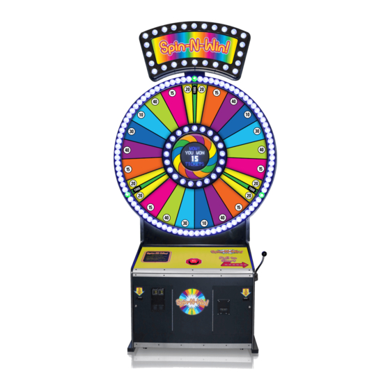
WELCOME TO: Spin-N-Win Congratulations on your purchase! With it’s bright and colorful vertical presence, Spin-N-Win is sure to grab the attention of your customers! Having to hit STOP at just the right time with have them spinning again and again! Please take a moment to read through this manual and be sure to contact our factory if you have any questions, or would like some more information. -
Page 5: Specifications
GAME SPECIFICATIONS POWER REQUIREMENTS WEIGHT INPUT VOLTAGE 100 to 120 220 to 240 NET WEIGHT 485 LBS. RANGE SHIP WEIGHT 540 LBS. INPUT FREQUENCY 50 HZ 60 HZ DIMENSIONS RANGE WIDTH 73” MAX OPERATING DEPTH 71” CURRENT HEIGHT 137” 6.0 AMPS @ 115 VAC OPERATING TEMPERATURE FAHRENHEIT 80-100... -
Page 6: How To Play
HOW TO PLAY Pull the handle to start game play. Time your play and press the button to stop lights on the highest ticket values. Win tickets based on the value of the space where you stopped the the light! -
Page 7: Set Up Guide
SET UP GUIDE TOOLS NEEDED FOR SET UP: • 9/16” wrench or socket and impact • Snips • Step ladder • 3 strong people Safely lift the marquee off the top of the console. Set the marquee off to the side for the time being. With assistance, carefully lift the playfield off the support beams and lean against a sturdy support for the time being. - Page 8 SET UP GUIDE Use the key taped to the top of the console to open the cash box door and remove the hardware kit inside. Remove the two longest bolts from the hardware kit along with two lock washers and two regular washers.
- Page 9 SET UP GUIDE Carefully lift the marquee piece up and set into place on top of the playfield. The marquee piece will slide in behind the wood piece attached to the back of the playfield. Secure the marquee to the playfield using the two long bolts and washers.
- Page 10 SET UP GUIDE Open the left side door on the back of the playfield. Locate cables CE6921, CE6938 and CE6942 - these will be hanging down from the inside top of the playfield. Route all three cables up and out the hole on the back of the playfield.
- Page 11 SET UP GUIDE Plug in cables CE6921, CE6938 and CE6942 (that were ran up from the playfield) into their corresponding match that are fed out the back of the marquee. Route excess cables back down into the hole on the back of the playfield. If desired, use the wire loom located inside the cash box and wrap around the cables to cover and protect them.
- Page 12 SET UP GUIDE Push the handle all the way down until it “clicks” and stays in the down position. *This next step of lifting the playfield/marquee up and top of the console will require three people. With one person on each of the sides and a spotter in the front, safely and carefully lift the playfield/marquee on top of the console.
- Page 13 SET UP GUIDE Once in place, use the six remaining bolts, lock washers and regular washers from the hardware kit to secure the playfield to the support beams. Three bolts will go in each support beam.
- Page 14 SET UP GUIDE Unlock the bottom lock on the left side rear door of the playfield - if needed, use a step ladder to reach. Remove the back door from the bottom console. Down inside the playfield, find the gray ribbon cable (CE6924) that is bundled up.
- Page 15 SET UP GUIDE In addition to the gray ribbon cable, locate cables CE6901, CE6909 and CE6937. Route these cables down the same oval cut out as the ribbon cable. These will fall inside the console. Plug in cables CE6901, CE6909 and CE6937 into their corresponding match that are already inside the console.
- Page 16 SET UP GUIDE Route the ribbon cable (CE6924) to the front of the console and over the circuit board platform. From the front of the console, plug in the ribbon cable to its housing located at the top right corner of the platform.
-
Page 17: Dip Switch Settings
DIP SWITCH SETTINGS The dip switch bank is located on the mainboard, inside the right side, front door of the game. *factory default settings are highlighted below SWITCH DESCRIPTION NEW JERSEY PROGRAMMING... -
Page 18: Main Menu Functions
MAIN MENU FUNCTIONS MENU DESCRIPTION Credits Per Play Game Volume Attract Volume Attract Timing Ticket Pattern Mercy Tickets 1/2 Ticket Dispense Fixed Ticket Payout Stored Tickets/Credits No Pull Timeout No Play Timeout Score Display Jackpot Window LED Brightness Tickets/Points Operation Call Attendant Jackpot Bell Statistics... - Page 19 N1- COINS/CREDITS PER PLAY Scroll through the N1 menu with the “MENU” button. Make your selection with the “SELECT” button. The factory settings are highlighted below. N2- GAME VOLUME Scroll through the N2 menu with the “MENU” button. Make your selection with the “SELECT” button. The factory settings are highlighted below.
- Page 20 N4- ATTRACT TIMING Scroll through the N4 menu with the “MENU” button. Make your selection with the “SELECT” button. The factory settings are highlighted below. This setting determines how often the attract loop audio is played. SEC. MIN. MINS. MINS. MINS.
- Page 21 N7- 1/2 TICKET DISPENSE Scroll through the N7 menu with the “MENU” button. Make your selection with the “SELECT” button. The factory settings are highlighted below. Enabling 1/2 ticket dispense will make the game dispense 1 paper ticket for every 2 tickets won. N8- FIXED TICKET PAYOUT Scroll through the N8 menu with the “MENU”...
- Page 22 N10- NO PULL TIMEOUT Scroll through the N10 menu with the “MENU” button. Make your selection with the “SELECT” button. The factory settings are highlighted below. This option will select the amount of time before the game will automatically start after coin up if there is no handle pull activity.
- Page 23 N13- JACKPOT WINDOW Scroll through the N13 menu with the “MENU” button. Make your selection with the “SELECT” button. The factory settings are highlighted below. This option controls the difficulty level of winning the jackpot. 1 is the most difficult. ADJUSTABLE IN INCREMENTS OF 1 M SEC.
- Page 24 N16- OPERATION Scroll through the N16 menu with the “MENU” button. Make your selection with the “SELECT” button. The factory settings are highlighted below. NORMAL MODE 1 CREDIT MAX N17- CALL ATTENDANT Scroll through the N17 menu with the “MENU” button. Make your selection with the “SELECT”...
- Page 25 N19- STATISTICS Press the SELECT button in N19 to scroll through the following: AVERAGE TICKETS PER GAME TOTAL NUMBER OF GAMES PLAYED TOTAL NUMBER OF TICKETS WON BUCKETS 1-27 (BUCKETS 1, 10 & 19 ARE JACKPOT SPACES) N20- CLEAR STATISTICS Scroll to the N20 menu with the “MENU”...
- Page 26 CUSTOM PAYOUT Holding the SELECT button for 5 seconds enters the ‘Custom Payout’ mode. This is where values can be adjusted to custom settings. The jackpot values range is: 50 to 1000 by 50’s 1000 to 2500 by 250’s Defaults are the currently selected payout table values. Adjacent sides have a range of: 1 to 20 by 1’s 20 to 50 by 5 ‘s...
-
Page 27: Ticket Patterns
TICKET PATTERNS SECTION SECTION SECTION SECTION SECTION SECTION PATTERN PATTERN $2.00/ D&B 50¢ GAME SECTION SECTION SECTION SECTION SECTION SECTION SECTION SECTION SECTION PATTERN $1.00/DEFAULT SECTION SECTION SECTION... - Page 28 TICKET PATTERNS SECTION SECTION SECTION SECTION SECTION SECTION PATTERN PATTERN 25¢ GAME 50¢ GAME SECTION SECTION SECTION SECTION SECTION SECTION...
-
Page 29: Mainboard Pinout
MAINBOARD PINOUT ... -
Page 30: Mainboard Pinout Guide
MAINBOARD PINOUT GUIDE BayTek NEWGEN1 Hardware REV G & up Pin Type Purpose =Low Side Driver Pin # LOWSIDE #1,w diode =High Side Driver LOWSIDE #2, w diode = TTL Input/Output LOWSIDE #3 = LED Constant Current Drive LOWSIDE #4 = 12 Volts LOWSIDE #5 = Ground... -
Page 31: How To: Access Display
HOW TO: ACCESS DISPLAY Remove the 4 screws from the front of the game. Remove the 4 screws from the back of the game. They are #2 square head. Open the left rear access door, and push the front vacuum form toward the front of the game while sliding the wood display mount from the notches in the back wood. -
Page 32: Circuit Board Layout
Circuit Board Layout CIRCUIT BOARD LAYOUT AACE6914 Stop Button Input AACE6943 Signal In AACE6914 AACB6921 To first Control Board LED bulb AACE6904 Voltage In AACE6900 AACE6900 Ticket Dispenser Low Ticket Switch AACE6900 LED control AACE6908 Cable to Speaker AACE6944 Com to Control Board AANEWGEN1-PJ/RBN +12 V... -
Page 33: Ticket Dispensers, Handle Switch & Coin Wiring Diagram
TICKET DISPENSERS, HANDLE SWITCH & COIN WIRING DIAGRAM Ticket Dispensers, Handle Switch & Coin Wiring Diagram Right Ticket Dispenser Left Ticket Dispenser Low Ticket Switch Low Ticket Switch Part # AASW200 Part # AASW200 To Ticket To Ticket Wired Normally Open Wired Normally Open Dispenser Dispenser... -
Page 34: Upper Section Power Supply Wiring Diagram
Upper Section Power Supply Wiring Diagram UPPER SECTION POWER SUPPLY WIRING DIAGRAM Display Board (Viewed from back) A5LD1052 Display Mod AACE6925 AACE6950 A5LD1052 Display Mod AACB6921 Control Board AACE6909 AACE6950 AACE6904 AACE6904 AACE6943 A5TB6900 A5TB6900 24 VDC 12 VDC AACE6909 Speaker Speaker AACE8811... -
Page 35: Lower Section Power Supply Wiring Diagram
Lower Section Power Supply Wiring Diagram LOWER SECTION POWER SUPPLY WIRING DIAGRAM To CE6909 Cable Continue CE6924 to To CE6937 Cable in Upper Section Display in Upper in Upper Section Section Stop Button & Light AAPB5900 AACB3904 Splitter AACE6923 To J19 on Newgen To J16 on Newgen... -
Page 36: Led Wiring Diagram
LED WIRING DIAGRAM (VIEW FROM FRONT) LED Wiring Diagram ( Viewed from Front) AACE6930 AACE6930 AACE6930 AACE6931 AACE6930 AACE6930 AACE6930 AACE6906 AACE6921 AACE6933 LED Light Strip AACE6945 LED Light Strip AACE6921 AACE6934 AACE6934 LED Light LED Light Strips Strips AACE6932 AACE6932 LED Light Strips LED Light Strips... -
Page 37: Led Bulb Wiring Diagram
Light Bulb Wiring Diagram ( Viewed from Front) LED BULB WIRING DIAGRAM (VIEW FROM FRONT) To the 26 Lights in the A5LD6900 AACE6946 Marquee AACE6947 Game has 4 special LED bulbs that have extra 2 power in wires. These 4 bulbs are part # AACE6946 AACE6938 Game has 128 normal LED bulbs. -
Page 38: Diagnostics
POWER SUPPLY DIAGNOSTICS 1.) Verify AC power to game. Check power strip in front door. The rocker switch should be illuminated. Power Strip 2.) Check power in connection to power supply. AACE6919 3.) Ensure Power Supply switch is set to 115V (or 230V) (Some model power supplies may not have this) 4.) Ensure Power switch is on. - Page 39 BILL ACCEPTOR DIAGNOSTICS Note: There are many different models and brands of Bill Acceptors that are used on redemption games. Your Bill Acceptor may differ from the unit shown. Standard DBA is MEI # AE2451-U5E Part # A5AC9091 Determine if Bill Acceptor has power: Turn game ON—The bill acceptor should make noise as stacker cycles and green lights on outside bezel should flash.
-
Page 40: Decal Diagram
DECAL DIAGRAM... -
Page 41: Trouble Shooting Guide
TROUBLE SHOOTING GUIDE Troubleshooting Strategy Use common sense and a systematic method of troubleshooting to determine the exact problem, probable cause and remedy. Use the process of elimination to find the fault component. Always check for the simple and obvious causes first such as unplugged, loose or broken wires and bad sensors, bent, pinched stuck or jammed components. - Page 42 TROUBLE SHOOTING GUIDE Problem Probable Cause Remedy Problem Probable Cause Remedy Game not coining up. Ensure game makes sound Check coin switches—both should be wired nor- when coin switch is triggered. mally open. If one switch is “closed” the other will Enter Diagnostic Menu to see not work either.
- Page 43 TROUBLE SHOOTING GUIDE Opto Sensor on ticket Blow dust from sensor and clean with Tickets do dispenser dirty. isopropyl alcohol. not dispense Faulty ticket dispenser. Replace with working dispenser to isolate the or Wrong Tickets on win problem. (A5TD1) amount spot does not dispensed.
- Page 44 TROUBLE SHOOTING GUIDE Problem Probable Cause Remedy Problem Probable Cause Remedy Display is dark The 5 Volt DC power to display board comes from power supply through cable #’s: CE6950, CE6909 & CE6905. Check for faulty cable, disconnected, loose or broken wires. The signal comes from the Newgen board through cables #’s: CE6925, CE6924, CE6923, and a splitter board (AACB3904) Check for faulty cable, disconnected, loose or broken wires.
- Page 45 TROUBLE SHOOTING GUIDE Problem Probable Cause Remedy Problem Probable Cause Remedy Faulty 24 VDC power from Check power from top of power supply. Unplug outputs power supply from power supply at re-test. Replace power supply if no All Flashing light 24 Volts DC out.
-
Page 46: Parts List
PARTS LIST PART # DESCRIPTION PART # DESCRIPTION A5CB8020 COIN BOX AACE3219 CABLE,TKT DISP/LOW TKT A5HA8500 HANDLE MECH ASSY AACE6900 CABLE ASSY, LOWER HANDLE, TICKET A5RO8700 PULL HANDLE ROD AACE6901 CABLE ASSY, SPEAKERS A5CA8704 CAM, STANDARD AACE6902 CABLE ASSY, NEW GEN POWER A5HU8500 HUB, SMOOTH, CHROME AACE6904... -
Page 47: Parts Pictures
PARTS PICTURES A5CORD5 A5FI9010 AACE6919 A5LK2000 A5LK5001 AAPS1013-SNW AACBL4A-DOOR AACE8811 AAPB2700 AANEWGEN1-RBN... -
Page 48: Maintenance Log
MAINTENANCE LOG If repairs are necessary, it is good practice to keep a log of repairs done and parts ordered. The chart below will assist you in tracking your game’s maintenance. DATE MAINTENANCE PERFORMED PARTS ORDERED INITIALS... -
Page 49: Technical Support
TECHNICAL SUPPORT Excellent customer service is very important to Bay Tek Games! We know that keeping your games in great operating condition is important to your business. When you need us, we are here to help. You can call us for free technical assistance, and you can count on us to have parts on-hand to support your game. -
Page 50: Warranty
WARRANTY Bay Tek Games warrants to the original purchaser that all game components will be free of defects in workmanship and materials for a period of 6 months from the date of purchase. If you fill out the registration card in the cashbox of the game, Bay Tek will add another 3 months to your warranty, free of charge.
Need help?
Do you have a question about the Spin-N-Win! and is the answer not in the manual?
Questions and answers