Table of Contents
Advertisement
Advertisement
Table of Contents

Related Manuals for Bay-Tek CONNECT 4 HOOPS


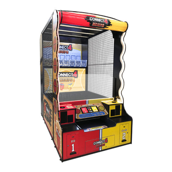
Summary of Contents for Bay-Tek CONNECT 4 HOOPS
- Page 1 SERVICE MANUAL PLACE SERIAL NUMBER LABEL HERE...
-
Page 2: Factory Contact Information
FACTORY CONTACT INFORMATION BAY TEK ENTERTAINMENT Pulaski Industrial Park 1077 East Glenbrook Drive Pulaski, WI 54162 USA SIGN UP TO RECEIVE OUR E-MAILS! Stay up to date on the latest game information, new products launches, early notification of parts specials, updates of retro fit parts, software upgrades, best practices and more! Visit baytekent.com and enter your email to sign up! You can also register your new game at baytekent.com/register SALES... -
Page 3: Table Of Contents
TABLE OF CONTENTS FACTORY CONTACT INFORMATION ……..…………………………. 2 TABLE OF CONTENTS...……………………………………………….. 3 WELCOME TO Connect 4 Hoops HD …………………………………. 4 GAME SPECIFICATIONS ……………………………………………… SAFETY PRECAUTIONS ……………………………………………… GAME SET UP ………………………………………………………. 6 - 21 HOW TO PLAY ……………………..…………………………………… 22 MAIN MENU FUNCTIONS ……………………………………………. -
Page 4: Welcome To Connect 4 Hoops Hd
WELCOME TO CONNECT 4 HOOPS HD Congratulations on your purchase! Please take a moment to read through this manual and be sure to contact us if you have any questions, or would like more information. Thank you for your purchase! Your business is important to us and we hope... -
Page 5: Game Specifications
GAME SPECIFICATIONS WEIGHT POWER REQUIREMENTS NET WEIGHT 1000lbs. 454 kg INPUT VOLTAGE 100 to 120 220 to 240 SHIP WEIGHT 1270 lbs. 576 kg RANGE INPUT FREQUENCY GAME DIMENSIONS 60 Hz 50 Hz RANGE WIDTH 61" 155 cm MAX OPERATING CURRENT DEPTH 112"... -
Page 6: Game Set Up
CONNECT 4 HOOPS HD SETUP SECTION ASSEMBLY UPPER REAR CABINET MARQUEE SECTION LOWER REAR CABINET MIDDLE CABINET FRONT CONSOLE... - Page 7 Connect 4 Hoops HD Shipping Checklist Game Serial # _______ Large Pallet Parts List: Large Pallet 76”x 54”x 86” 860 lbs. class 125 2 Side Cages Part 5 (Part # AAME15019) Middle Cabinet Part B Lower Rear Cabinet Middle Lower Rear Cabinet Part N Cabinet Cardboard Box # 2 (76 1/2”...
- Page 8 Connect 4 Hoops HD Shipping Checklist Game Serial # _______ Small Pallet Parts List: Upper Rear Small Pallet 76”x 34”x 86” 410 lbs. class 250 Cabinet Front Console Part M 6 Game Balls (Part # A5BA15000) Wood Platform Service Manual...
- Page 9 CONNECT 4 HOOPS HD SETUP The game will arrive on 2 pallets with 2 cardboard boxes of parts. Please inspect the pallets for shipping damage and report immediately to the freight company if any damage found. There will be about 5 hours of assembly time needed.
- Page 10 CONNECT 4 HOOPS HD SETUP From the small pallet, unwrap and remove Cardboard Box # 1 - set aside for later use. Upper Rear Cabinet Using 3 people, remove the wood platform (Part A) from the shipping configuration by removing the 4 Phillips bolts.
- Page 11 CONNECT 4 HOOPS HD SETUP Upper Rear Cabinet Carefully lift upper rear cabinet up onto the top of the bottom rear cabinet. It will slide into position as shown. Lower Rear Cabinet Locate the 2 of metal rear connector plates. Part 1 from box # 1.
- Page 12 CONNECT 4 HOOPS HD SETUP Locate part C (wood diverter) from box # 1 and affix to part B as shown with 4 of black 10 X 5/8” screws using a # 2 Square Head bit. A5SCPH150 Similarly, locate part D (wood diverter) from box # 1 and affix to part B as shown with 4 of black 10 X 5/8”...
- Page 13 CONNECT 4 HOOPS HD SETUP Similarly, locate part F (right side) from box # 1 and affix to part B as shown with 3 of black #8 X 1¼” Bugle screws using a # 2 Square Head bit. A5WALO010 Make sure the front and rear edge of part F is aligned properly with the lower cabinet.
- Page 14 CONNECT 4 HOOPS HD SETUP Position the middle cabinet up tight against the rear cabinet. Locate the 2 of the middle connector plates. Part 2 from box # 1. Install the plates on the side of the cabinet with 16 of the black ¼-20 X 1”...
- Page 15 CONNECT 4 HOOPS HD SETUP On the right side, plug the white connectors (CE15022 to CE15023) and power cords together. Position the front console up tight against the middle cabinet assembly. Locate the 2 of the middle connector plates. Part 3 from box # 1.
- Page 16 CONNECT 4 HOOPS HD SETUP Build Marquee: Locate parts H, K, L, and the 2 J’s from box # 2. Lay out the boards on the floor as shown: (The 2 J pieces are interchangeable.) Using 2 people, one at each end, position the 3 boards (H, L , &...
- Page 17 CONNECT 4 HOOPS HD SETUP Carefully stuff the wire light cables inside the gap of the white cover as the notches are lined up and wood is slid together. This will provide the corner with a nice, clean finish. Install corners (J) on assembly with 8 of black 10 X 5/8” screws using a # 2 Square Head bit.
- Page 18 CONNECT 4 HOOPS HD SETUP Option A: Standard mounting under the roof Remove the circular marquee from Box # 2. Install circular marquee: Using 2 people, stand the assembly upright on the floor in front of the game. Be sure the white plastic is facing out into the game room.
- Page 19 CONNECT 4 HOOPS HD SETUP Option B: Mounting on top of game The brackets will have to be flipped on the marquee. Remove the circular marquee from Box # 2. Lay on floor as shown. On yellow side - Remove the 4 bolts using a Phillips screwdriver.
- Page 20 CONNECT 4 HOOPS HD SETUP Continuing Assembly with either option: Plug in the marquee power cable to the cable on the top left side of assembly. There is also a coiled cable there that will be used later in the installation.
- Page 21 CONNECT 4 HOOPS HD SETUP Using a 6 foot ladder, install 2 of the black ¼-20 X 1 Phillips head bolts using a # 3 Phillips Head bit on the top front end of cage. This will secure the cage to the front marquee.
-
Page 22: How To Play
HOW TO PLAY Choose a side and insert your credits; 6 balls will appear in the ball area. Wait for a partner to join, or shoot a ball to play solo! Shoot when it is your turn. Be the first to align 4 of your basketballs horizontally, vertically, or diagonally to win! Collect your tickets once you Connect 4! -
Page 23: Main Menu Functions
MAIN MENU FUNCTIONS The Menu and Menu Select buttons are located inside the center lower front door. Hold the MENU button down for 1 second to open the main menu on the display. Press MENU to scroll through the options, and MENU SELECT to change the settings. -
Page 24: Volume & Attract
VOLUME & ATTRACT SETTINGS Scroll through the options by pressing the “MENU” button. Change selection with the “SELECT” button. Scroll to “BACK” and press the “SELECT” button to go back to the main menu. Default settings are highlighted in yellow below. GAME VOLUME Change selection with the “SELECT”... -
Page 25: Game Settings
GAME SETTINGS Scroll through the options by pressing the “MENU” button. Change selection with the “SELECT” button. Scroll to “BACK” and press the “SELECT” button to go back to the main menu. Default settings are highlighted in yellow below. GAME MODE / PAYMENT NORMAL / TICKETS NORMAL / POINTS NORMAL / COUPONS AMUSEMENT ONLY SHOW MODE “NORMAL / TICKETS”... -
Page 26: Payout Settings
PAYOUT SETTINGS Scroll through the options by pressing the “MENU” button. Change selection with the “SELECT” button. Scroll to “BACK” and press the “SELECT” button to go back to the main menu. Default settings are highlighted in yellow below. CREDITS Sets the amount of credit pulses needed to start a game. -
Page 27: Ticket Patterns
TICKET PATTERNS WINNER LOSER AVERAGE TICKETS PRICE PER PLAY These are estimates of Average TICKETS TICKETS PER GAME Tickets per Game using the shown ticket values for 14-16 $.50 PER PLAY game winner and game loser. 34-36 $1.00 PER PLAY Change ticket values in the 48-52 $1.50 PER PLAY... -
Page 28: Diagnostics
DIAGNOSTIC MENU The Diagnostic Menu can be entered by selecting ON in the Main Menu, and then exiting the menu. The ball gate motor will cycle open, and this screen will appear: The top column will show hoops scored. Diagnostic window will show: Credits switch activated Ticket notch activated Input changes... -
Page 29: Card Swipe Installation
CARD SWIPE SYSTEM INSTALLATION The Connect 4 Hoops game is pre-wired with a UCL (Universal Card Link) connector to accept Card Swipe systems from many different manufactures. Please follow these instructions to make full use of this capability. Option #1: Card swipe systems may come with a standard 9 pin Molex connector. -
Page 30: Circuit Board Layout
CIRCUIT BOARD LAYOUT AACE15036 Hoop Sensors AACE15018 Red Connector AACE15018 Yellow Connector AACB10000 AACE15000 Control Board LED Strip Under Baskets AACE15011 Motor & Sensor A5CORD40 AACE15015 USB Communication Power in from to Motherboard Power Dist Bd AACE15013 12 V Power to Right Coin Door AACB9600A... -
Page 31: Wiring Diagrams
WIRING DIAGRAM LEFT SIDE (RED) : TICKET DISPENSER, MENU BUTTONS, METERS, DBA AND COIN MECH AAPB2700 Menu From Right Side Button I/O Aux Board Red and Yellow Green AACE15010 Communication Power AAPB2700 Menu LEDs Select AACE15010 A5CBL5900 USB communication to motherboard Game Counter AACO1020... - Page 32 WIRING DIAGRAM RIGHT SIDE (YELLOW) : TICKET DISPENSER, DBA AND COIN MECH Red and Yellow Green Communication Power AACE15010 LEDs To Left Side A5CBL5900 Game and USB communication Ticket Meters to motherboard Right Side Board Address Dips #1 ON Dip #2 OFF Low Ticket Switch Wired Normally Open AASW200...
- Page 33 LED LIGHTING WIRING DIAGRAM AACB10000 Control Board AALB15000 A5CB15000 AACE15000 1st LED strip The other 6 LED strips under hoop under hoops AACE15018 AACE15015 Rear Section Pink Yellow Connectors Connectors Middle Section AACE15016 AACE15019 Middle Section Gold Green Connectors Connectors Front Console AACE15041 AACE15041...
- Page 34 LED LIGHTING WIRING DIAGRAM Back of Cabinet LED lighting above hoops AALB15044 AALB15045 Rear Section Top Front Marquee Cable across the top left side of game AALB15047 AALB15047 AACE15005 LED Lighting Inside Marquee Tube AALB15047 AALB15048 AACE15005 Cable is inside front left support pole Top Front Marquee...
- Page 35 WIRING DIAGRAM BALL GATE MOTOR, SENSOR AND HOOP SENSORS Detector Emitters A5CB10001 A5CB10001 All ball sensor boards have 4 emitters and 1 detector on opposite sides of the board. The far left (#1) board can be swapped into a location with a faulty emitter.
- Page 36 COMMUNICATION WIRING DIAGRAM Monitor AACB10000 A5MO0065A Control Board A5CORD36 8’ HDMI Cable Rear Section Connection Middle Section A5CORD40 USB Communication to A5CORD37 rear Controller Board 15’ HDMI Cable Middle Section Connection Front Console Note: Later games may have Note: different colored sockets. Older games had 3 separate A5CORD51 The connections are the same.
- Page 37 12 V POWER SUPPLY & SOUND WIRING DIAGRAM # 8 # 7 # 6 # 5 # 4 # 3 # 2 # 1 AACB10000 Control Board AACE15015 Pink Connectors Rear Section Middle Section AACE15016 Middle Section Gold Connectors Front Console Speaker Speaker AACE8811...
- Page 38 AC POWER IN WIRING DIAGRAM Power In Cord From Wall AC Bleeder Monitor Power Cord is A5CORD5-A Board attached to A5MO0065A AACB15001 monitor Line Filter Note: A5FI9010 This section is only for early games manufactured before 9/5/2019 AC Power In cable A5CORD50 AACE15042 Power In Cord...
-
Page 39: Diagnostics
TROUBLESHOOTING GUIDE Troubleshooting Strategy Use common sense and a systematic method of troubleshooting to determine the exact problem, probable cause and remedy. Use the process of elimination to find the faulty component. Always check for the simple and obvious causes first such as unplugged, loose or broken wires and bad sensors, bent, pinched, stuck or jammed components. - Page 40 TROUBLESHOOTING GUIDE Problem Probable Cause Remedy Game not coining up Look for communication and Refer to “I/O Aux Board Issue” power on the I/O Aux Board diagnostic section. Enter Diagnostic Mode (Turn for that player. diagnostics on, then exit menu) to see if Credits Ensure game makes sound Check coin switches—both should be wired nor- Increment when coin is...
- Page 41 TROUBLESHOOTING GUIDE Problem Probable Cause Remedy LED’s receive 12 Volts DC Check for proper connection from power supply to Power from power supply through Distribution Board. LED white rear The Power Distribution Refer to wiring diagram. Check connections and reseat cabinet lighting Board.
- Page 42 TROUBLESHOOTING GUIDE Problem Probable Cause Remedy If all colored cabinet lights Refer to wiring diagram. Check connections and reseat One of the right are not functioning, check cables from Power Distribution Board in the front of the side, yellow power into the Control cabinet to Control Board in the back.
- Page 43 TROUBLESHOOTING GUIDE Problem Probable Cause Remedy Opto Sensor on ticket Blow dust from sensor and clean with Tickets do dispenser dirty. isopropyl alcohol. not dispense Faulty ticket dispenser. Replace with working dispenser to isolate the or Wrong Tickets on problem. (A5TD1) amount monitor does dispensed.
- Page 44 TROUBLESHOOTING GUIDE Problem Probable Cause Remedy Check for 12 volts to sensor There should always be 12 volts on the yellow and Ball Gate Motor and 5 volt signal return. blue wires. keeps running. 5 volts on the white and blue wires when blocked and Motor will cycle at 0 volts when not blocked.
-
Page 45: Hoops Not Scoring
HOOPS NOT SCORING All ball sensor boards have 4 emitters and 1 detector on opposite sides of the board. These infrared sensors create a beam which the ball breaks to score a hoop. Because these are interchangeable, the far left (#1) board can be swapped into a location with a faulty emitter. The far right (#8) board can be swapped into a location with a faulty detector. -
Page 46: Power Supply Diagnostics
POWER SUPPLY DIAGNOSTICS 1.) Verify AC power to game. Check power strip in front door. The rocker switch should be illuminated. 2.) Check connection to power supply. 3.) Ensure Power Supply switch is set to 115V (or 230V) (Some model power supplies may not have this) 4.) Ensure Power switch is on. -
Page 47: Bill Acceptor Diagnostics
BILL ACCEPTOR DIAGNOSTICS Note: There are many different models and brands of Bill Acceptors that are used on redemption games. Your Bill Acceptor may differ from the unit shown. Standard DBA is MEI # AE2454-U5E Part # A5AC9101 Determine if Bill Acceptor has power: Turn game ON—The bill acceptor should make noise as stacker cycles and green lights on outside bezel should flash. -
Page 48: How To Access Ball Sensor
HOW TO ACCESS BALL SENSORS The ball hoop sensors are accessed through the back of the cabinet, or through the middle platform access panel. If the game is up against the wall, carefully climb over the plexi shield (or remove the plexi) and enter the middle section of the game. -
Page 49: Monitor Default Settings
MONITOR DEFAULT SETTINGS Monitor setting screen shots. Model # D65A214-U-A... -
Page 50: How To Replace Monitor
HOW TO REPLACE MONITOR The monitor is protected by tempered glass. The glass will be removed first, then the monitor. Tools needed: Phillips bit screwdriver # 2 Square bit 7/16” Wrench Remove the plexi shield from game and set aside. Climb into the middle section of the game. - Page 51 HOW TO REPLACE MONITOR Remove the 2 Phillips screws on each upper left and right corner black plastic piece. Lift up on monitor to unhook the wood attaching monitor to back frame. Set down to unhook cables. Remove the cable clamp on HDMI cable on the left side of monitor using # 2 square bit.
-
Page 52: How To Move Marquee To Top Of Game
HOW TO MOVE MARQUEE TO TOP OF GAME If you have at least 9 inches of clearance above your game, the round marquee may be installed on top of the game. This is a matter of personal preference: Standard mounting under the roof Optional mounting on top Tools needed: 7/16”... -
Page 53: How To Update Software
HOW TO UPDATE SOFTWARE New Software Installation: The hard drive contains all the information about the game: Credits per play, ticket pattern, etc. Be sure to check this information after finishing installing new software. Turn off game by flipping the power switch on the power strip. Locate hard drive on motherboard. -
Page 54: Dipswitch Settings
DIPSWITCH SETTINGS Dipswitches must be set correctly on the I/O Aux Boards or game will not know which is left or right player. Turn off game by flipping the power switch on the power strip. Set dipswitches as shown: Left Side (Red Player) Right Side (Yellow Player) Both switches 1 and 2 should be set to OFF Set switch 1 to ON , Set switch 2 to OFF... -
Page 55: Ball Gate Exploded View
BALL GATE EXPLODED VIEW A5SCSQ001 A5ME15006 A5SCPH190 A5BOEY010 A5NULO040 A5BOCG065 A5NULO040 A5BRZN030 A5HKSY020 W5HG1030 A5SREX050 A5HKSY020 Part # Description A5HKSY020 S Hook A5SCSQ001 #6 X 3/4" Screw A5BOCG065 10-24 x 1 1/4" Bolt A5ME15006 Ball Gate A5SREX050 3/8" X 6" Spring A5BOEY010 10-24 Eye Bolt A5NULO040... - Page 56 BALL GATE EXPLODED VIEW A5PICV032 A5SLLO020 WARR0002-C4HP A5PICV045 WARR0001-C4HP A5SP10000 A5SLLO020 A5SP10000 A5NUNY040 A5WAFL040 A5BOPH190 A5PICV032 A5NUTE020 A5ME1727 A5SLLO020 A5WAFL060 A5BOHH050 A5MO5154 A5SENY170 A5PICV045 A5SLLO020 WAC4H0001 A5BOHH050 A5WASI020 A5WAFL060 Part # Description A5SENY170 1/4 " X 1/4" Nylon Spacer A5BOHH050 25-20 x 1 1/4"...
-
Page 57: Parts List
PARTS LIST PART # DESCRIPTION PART # DESCRIPTION 94639A207 Spacer, Nylon 1/4"Od,5/16"Lg,#4 A5DE15020 Decal, Left Red Shelf Decal A5BA15000 Basketball W/Logo, Mini, Size 3 A5DE15014-1 Decal, Cab Side Left Bottom Panel AABK1013 Bracket, Pushbutton/Counters A5DE15014-2 Decal, Cab Side Left Top Panel A5BK9999 Bracket, Power Supply Mounting A5DE15021... -
Page 58: Parts Pictures
PARTS LIST PART # DESCRIPTION PART # DESCRIPTION A5CB15000 Hoop Light Board, not 1st AACE15037 Cable Assy,Cb9600 To Power Distribution AACE15000 Cable Assy, Hoop Addressable Light Power AACE15038 Cable Assy, Power Distribution To Boards AACE15001 Cable Assy, Right Dba AACE15039 Cable Assy, Side Rail Led AACE15002 Cable Assy, Left Dba... - Page 59 PARTS PICTURES A5LK5002 A5LV10000 A5OU5000 A5PL4200 A5PL8900 A5SSLL020 A5SREX050 AASW200 A5VF4604 AACO1020 W5HG1025 W5HG1030 W5HG1040 W5HG1065 W5KE5000 W5TM4000 A5DE15000 A5DE15001 A5DE15002 A5DE15003 A5DE15004 A5DE15005 A5DE15006 A5DE15007 A5DE15008 A5DE15009 A5DE15010 A5DE15011 A5DE15012 A5DE15013 A5DE15014-1 A5DE15014-2 A5DE15020 A5DE15021 A5DE15015-1 A5DE15015-2 A5DE15016 A5DE15019 A5DE10021 A5ME10001 A5ME1727 A5ME4179 A5CBL4A-DOOR A5CBL5900 A5CE2300 A5CE6601...
- Page 60 PARTS PICTURES AACE15001 AACE15002 AACE15003 AACE15005 AACE15006 AACE15007 AACE15008 AACE15009 AACE15010 AACE15011 AACE15012 AACE15013 AACE15014 AACE15015 AACE15016 AACE15017 AACE15018 AACE15019 AACE15020 AACE15022 AACE15024 AACE15025 AACE15026 AACE15027 AACE15028 AACE15036 AACE15037 AACE15038 AACE15039 AACE15040 AACE15041 AACE1710 AACE1715 A5MO5154 A5PS1013 A5TD1 AACE8811 AAPB2700 A5CB5190A AACB9600A AACB10000...
-
Page 61: Decal Diagram
DECAL DIAGRAM... -
Page 62: Maintenance Log
REPAIR/MAINTENANCE LOG If you need to make repairs or order replacement parts it is a good idea to keep a log. Below is a chart you can use to track repairs and maintenance. DATE MAINTENANCE PERFORMED PARTS ORDERED MISC. NOTES... -
Page 63: Technical Support
TECHNICAL SUPPORT Excellent customer service is very important to Bay Tek Entertainment! We know that keeping your games in great operating condition is important to your business. When you need us, we are here to help. You can call us for free technical assistance, and you can count on us to have parts on-hand to support your game. -
Page 64: Warranty
WARRANTY OPTIONS Bay Tek Entertainment warrants to the original purchaser that the game will be free of defects in workmanship and materials for a period of 2 years from the date of shipping. Bay Tek Entertainment will, without charge, repair or replace at it's option defective product or component parts upon notification to the parts/service department. - Page 65 CONNECT 4 HOOPS HD PARTS LIST Parts List: Large Pallet 76”x 54”x 86” 860 lbs. class 125 2 Side Cages Part 5 (Part # AAME15019) Middle Cabinet Part B Lower Rear Cabinet Part N Cardboard Box # 2 (76 1/2” by 30” by 9 1/2”)
Need help?
Do you have a question about the CONNECT 4 HOOPS and is the answer not in the manual?
Questions and answers