
Related Manuals for Bay-Tek Pop the Lock


Summary of Contents for Bay-Tek Pop the Lock
- Page 1 Licensed By: Simple Machine and its logo and Pop The Lock are trademarks of Simple Machine and are used with permission. © Simple Machine. All Rights Reserved.
-
Page 2: Factory Contact Information
FACTORY CONTACT INFORMATION BAY TEK GAMES INC. Pulaski Industrial Park 1077 East. Glenbrook Drive Pulaski, WI 54162 USA JOIN OUR SERVICE FIRST NETWORK! This free service is intended to keep you up to date on the latest game information, early notification of parts specials, pertinent technical bulletins, updates on retro fit parts, software upgrades, and much more. -
Page 3: Table Of Contents
WELCOME TO: Pop The Lock ........4... -
Page 4: Welcome To: Pop The Lock
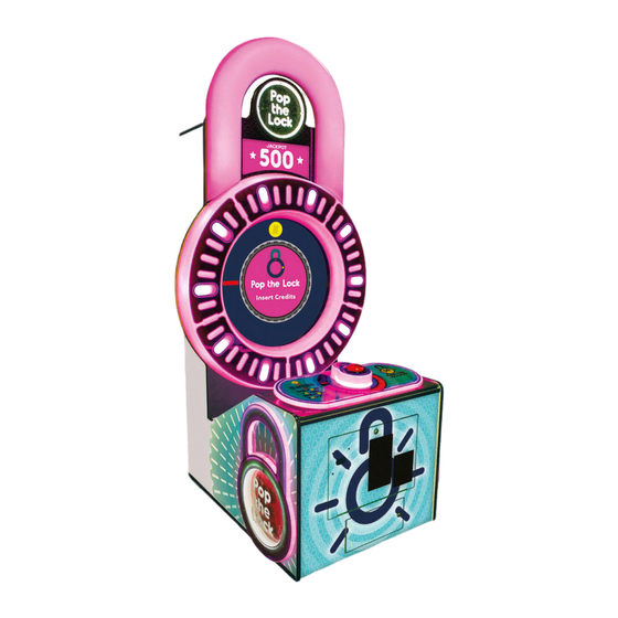
With it’s challenging skill-based game play that leaves players wanting to continue their play, Pop the Lock will have you unlocking new profits and fun! Please take a moment to read through this manual and be sure to contact our factory if you have any questions, or would like some more information. -
Page 5: How To Play
HOW TO PLAY Press the button to stop the red bar on the yellow dots. Win tickets for successful hits. 50 in a row wins the jackpot! -
Page 6: Specifications
GAME SPECIFICATIONS WEIGHT POWER REQUIREMENTS NET WEIGHT 400 LBS. INPUT VOLTAGE 100 to 120 220 to 240 RANGE SHIP WEIGHT 450 LBS. INPUT FREQUENCY DIMENSIONS 50 HZ 60 HZ RANGE WIDTH 44.5” MAX OPERATING DEPTH 44” CURRENT 97” HEIGHT (88.75” without ‘hasp’) 1.4 AMPS @ 115 VAC OPERATING TEMPERATURE .8 AMPS @ 230 VAC... -
Page 7: Setup Guide With Hasp
SETUP GUIDE WITH HASP CAUTION USE CAUTION WHEN RELEASING THE LATCHES! THE MONITOR FACE IS A FALL HAZARD AND COULD CAUSE DAMAGE! GET ASSISTANCE FROM SOMEONE IF NEEDED. Remove back door of game and set aside. Release the four latches - two found inside the back of the cabinet on both sides and two on the outside top. - Page 8 SETUP GUIDE WITH HASP CONT. Carefully lift the circular “Pop The Lock” marquee piece on top of the monitor face and slide into place, being careful not to pinch the cable. Locate the marquee hardware kit in the cashbox. Secure the marquee piece in place using...
- Page 9 SETUP GUIDE WITH HASP CONT. Route the cable from the circular piece through the channel on the back of the monitor face. Plug cable CE5931 from the circular marquee piece into cable CE5932. Get assistance from someone and place the hasp piece near it’s proper location. Route cable CE 5926-1 from the hasp piece, through the circle cut out in the monitor face.
- Page 10 SETUP GUIDE WITH HASP CONT. Secure the hasp piece in place using the four included bolts and washers. Tighten in place. Lift the monitor face/vacuum form up towards the monitor. Route all wires through the rear before pinching them. Rehook the latches in the top rear of the cabinet to secure the face in place.
- Page 11 SETUP GUIDE WITH HASP CONT. Plug in cable CE5903 to cable CE5926-1. Plug in cable CE5930-1 to cable CE5901. Plug in cable 5918 to the small circuit board on the side of the cabinet and the single red wire from CE5932. Replace the back door and lock.
-
Page 12: Height Modification Options
HEIGHT MODIFICATION OPTIONS... -
Page 13: How To: Access Monitor
HOW TO: ACCESS MONITOR Remove back door of cabinet and set off to the side. Unplug cables CE5919 and CE5930 from the circuit board located to the left rear in the back of the cabinet. Release the four latches - two found inside the back of the cabinet on both sides and two on the outside top. -
Page 14: Dip Switch Settings
DIP SWITCH SETTINGS The dip switch bank is located on the mainboard, inside the front door of the game. *factory default settings are highlighted below SWITCH DESCRIPTION New Jersey Programming... -
Page 15: Main Menu Functions
MAIN MENU FUNCTIONS Press and hold the MENU button located inside the front door to access the Main Menu. Scroll through the options with the MENU button. Make your selections with the MENU SELECT button. Factory defaults are highlighted below. MAIN MENU OPTIONS CLEAR CREDITS/ Press the MENU SELECT button 3 times to clear tickets and credits owed... -
Page 16: Volume & Attract Settings
VOLUME & ATTRACT SETTINGS MENU Factory defaults are highlighted below. VOLUME & ATTRACT OPTIONS ATTRACT VOLUME GAME VOLUME JACKPOT VOLUME ATTRACT TIMING (MINUTES) (OFF) BG MUSIC VOLUME ENABLED DISABLED BACKGROUND MUSIC... -
Page 17: Game Settings
GAME SETTINGS MENU Factory defaults are highlighted below. GAME SETTINGS OPTIONS TRAINING ATTEMPTS Number of times game allows for player to continue playing until a successful hit is made CONTINUE TIME Amount of seconds allowed for a player to insert credits & continue play ENTERTAINMENT GAME MODE/PAYMENT NORMAL/TICKETS... - Page 18 ADVANCED SETTINGS MENU Normal Factory defaults are highlighted below. GAME SETTINGS OPTIONS CONTINUES ALLOWED UNLIMITED Number of times game allows for player (disabled) (INC 1) to continue playing same game DIAL SPEED EASIEST EASY NORMAL HARD HARDEST Adjusts overall game difficulty - making the dial rotate slower or quicker DIAL ACCELERATION EASIEST...
-
Page 19: Payout Settings
PAYOUT SETTINGS MENU Factory defaults are highlighted below. PAYOUT MENU OPTIONS CREDITS PER PLAY FREE PLAY DEFAULT: 4 (INC 1) SWIPE PROMPT/CARD ENABLED DISABLED READER Changes “Credits 0/4” to “Swipe Card” PAPER TICKET VALUE FIXED TICKETS DEFAULT: 0 (INC 1) MERCY TICKETS TICKETS AWARDED FOR AMOUNT OF HITS SET BELOW... -
Page 20: Ticket Patterns
TICKET PATTERNS TICKET PATTERNS AVG. CONTINUE JACKPOT TIX PER TIX/HIT BONUS BONUS GAME AMOUNT AMOUNT 1/10 1000 1000 1000 *ADJUST TO ONLY 1 CONTINUE ALLOWED IN ‘ADVANCED SETTINGS’... -
Page 21: Statistics
STATISTICS STATISTICS Total Games Played Number of games played since last reset Total Tickets Number of tickets payed out since last reset Total Continues Number of times players selected the ‘continue game’ option Continue Winners The number of games won on “continue game” option Jackpot Winners Number of times Jackpot has been won Average Tickets... -
Page 22: Circuit Board Layout
CIRCUIT BOARD LAYOUT Circuit Board Layout AAMB9A-SHD Motherboard AACB5156 Power Dist. Board AACE5911 AACE5911 AACE5909 Ticket Dispenser Low Ticket Switch Stop Light A5CB2204A Interface Board AACE5920 LED control AACE5908 Cable to Speaker AACE5914 Com with Motherboard AANEWGEN1-PJ/RBN A5CEAU010 Sound Input From +12 V Motherboard AACE5920... -
Page 23: Mainboard Pinout
MAINBOARD PINOUT... -
Page 24: Pinout Guide
MAINBOARD PINOUT GUIDE Pin Type Purpose Pin Type Purpose Pin # Pin # LOWSIDE #1,w Ground diode Ground LOWSIDE #2, w +12 Volts diode +12 Volts LOWSIDE #3 Game Counter Play Button LOWSIDE #4 Ticket Counter LOWSIDE #12 Play Button Light LOWSIDE #5 PX29 LOWSIDE #6... -
Page 25: Troubleshooting
TROUBLESHOOTING GUIDE Troubleshooting Strategy Use common sense and a systematic method of troubleshooting to determine the exact problem, probable cause and remedy. Use the process of elimination to find the faulty component. Always check for the simple and obvious causes first such as unplugged, loose or broken wires and bad sensors, bent, pinched, stuck or jammed components. - Page 26 TROUBLESHOOTING GUIDE Problem Probable Cause Remedy Game not coining up. Look for “Check Newgen Refer to “Check Newgen Comm” error diagnostic Comm” error on screen. section. Enter Diagnostic Menu to see if Coin input goes to ON Ensure game makes sound Check coin switches—both should be wired nor- quickly when coin is inserted.
- Page 27 TROUBLESHOOTING GUIDE Problem Probable Cause Remedy LED’s to light up playfield Check for proper connection from power supply to Power receive 12 Volts DC from Distribution Board and then to LED strips. LED white lower power supply through the Check continuity. (AACE5936, AACE5936, AACE5934, cabinet lighting Power Distribution Board.
- Page 28 TROUBLESHOOTING GUIDE Opto Sensor on ticket Blow dust from sensor and clean with Tickets do dispenser dirty. isopropyl alcohol. not dispense Faulty ticket dispenser. Replace with working dispenser to isolate the or Wrong Tickets on problem. (A5TD1) amount monitor does dispensed.
- Page 29 TROUBLESHOOTING GUIDE Problem Probable Cause Remedy Monitor HDMI cable unplugged. Monitor shows “No Signal Detected” Faulty or loose RAM Large power connector unplugged on motherboard AAMB9A-SHD Faulty power supply - Refer to Power Supply diagnostic section Monitor Faulty motherboard - Replace faulty board. (AAMB9A-SHD) working.
-
Page 30: Wiring Diagrams
WIRING DIAGRAMS AC in, Power Supply Wiring Diagram AC IN, POWER SUPPLY WIRING AACE5936 Lower Right Circle LED AACB5156 Power Dist. Bd AACE5936 Lower Left Circle LED AACE5934 Inside cabinet Work LED To CE5920 Cable AACB5900 AACE5915 Light Board To CE5932 Cable Power Supply Cables SATA Hard... - Page 31 WIRING DIAGRAMS Light Board Wiring Diagram LIGHT BOARD WIRING From Newgen AACE5933 Board From Power AACE5915 Distribution Board AACB5900 Light Board These output cables are interchangeable AACE5905 AACE5904 AACE5902 AACE5900 AACE5903 AACE5901 Not Used AACE5927 AACE5923 Right Side Right Side Lock Lock Outside...
- Page 32 WIRING DIAGRAMS Coin Mech, Menu & Counter Wiring Diagram COIN MECH, MENU & COUNTERS WIRING Game Stop Light Low Ticket Switch A5PB5900 To Ticket Wired Normally Open Dispenser AASW200 Part # A5TD1 1/4” Spacer A5SENY020 Notch Signal Com Ground Enable Signal Wires to switch come 12 Volt Power AACE5911...
- Page 33 WIRING DIAGRAMS COIN MECH, MENU & COUNTERS WIRING From Power Dist. Bd. AACE5931 Marquee LED A5CE5918 AACE5932 Coin Switches and Lights Red LED only blinks at power ON. From Power AACBL4A-DOOR Dist. Bd. AACB9503-PTL Chase Board AACE5920 AACE5920 AACE5920 To J21 on main board.
- Page 34 WIRING DIAGRAMS Motherboard Communication Wiring Diagram MOTHER BOARD COMMUNICATION WIRING Game Stop Switch A5PB5900 Switch is wired normally open. Stop Switch Board AACB5902 A5CEAU010 Audio Jack from green socket on Motherboard to Newgen Board 55”TV A5MO5500 A5CORD35A AAMB9A-SHD HDMI Cable to Monitor TV AACE5913 Communication cable from J2 on...
-
Page 35: Power Supply Diagnostics
POWER SUPPLY DIAGNOSTICS 1.) Verify AC power to game. Check power strip in front door. The rocker switch should be illuminated. 2.) Check connection to power supply. 3.) Ensure Power Supply switch is set to 115V (or 230V) (Some model power supplies may not have this) AACB5156 4.) Ensure Power switch is on. -
Page 36: Dba Diagnostics
DBA DIAGNOSTICS Note: There are many different models and brands of Bill Acceptors that are used on redemption games. Your Bill Acceptor may differ from the unit shown. Standard DBA is MEI # AE2451-U5E Part # A5AC9091 Determine if Bill Acceptor has power: Turn game ON—The bill acceptor should make noise as stacker cycles and green lights on outside bezel should flash. -
Page 37: Parts List
PARTS LIST PART # DESCRIPTION PART # DESCRIPTION A5ME5900 METAL,BOTTOM RAIL AACE5900 CABLE ASSY, CONTROL PANEL LIGHT A5BK1013 BRACKET,PUSHBUTTON/COUNTERS AACE5901 CABLE ASSY, LOCK SURROUND LEDS A5BK6035 BRACKET,LIGHT AACE5902 CABLE ASSY, BOTTOM LIGHT HOLDER A5CB1499 COIN BOX AACE5903 CABLE ASSY, LOCK LATCH LEDS A5CN1031 CONN,ADAPTER 9POS F-RJ45 AACE5904... -
Page 38: Parts Pictures
PARTS PICTURES A5PL9097 A5CA1002 A5VF2002 A5CE1801 A5CN1031 A5CEAU010 A5CORD11 A5CORD23 A5CORD5 A5FI9010 A5OU1000 A5LK2000 A5LK5001 A5PS1008 A5CN1031 AACBL4A-DOOR AACE8811 AAPB2700 A5CB2204A AAMB9A-SHD AANEWGEN1-PJ/RBN... -
Page 39: Decals Diagram
DECALS DIAGRAM... -
Page 40: Technical Support
TECHNICAL SUPPORT Excellent customer service is very important to Bay Tek Games! We know that keeping your games in great operating condition is important to your business. When you need us, we are here to help. You can call us for free technical assistance, and you can count on us to have parts on-hand to support your game.
Need help?
Do you have a question about the Pop the Lock and is the answer not in the manual?
Questions and answers