Table of Contents
Advertisement
Advertisement
Table of Contents

Related Manuals for Bay-Tek AXE MASTER


Summary of Contents for Bay-Tek AXE MASTER
- Page 1 SERVICE MANUAL PLACE SERIAL NUMBER LABEL HERE...
-
Page 2: Factory Contact Information
FACTORY CONTACT INFORMATION BAY TEK ENTERTAINMENT Pulaski Industrial Park 1077 East Glenbrook Drive Pulaski, WI 54162 USA SIGN UP TO RECEIVE OUR E-MAILS! Stay up to date on the latest game information, new products launches, early notification of parts specials, updates of retro fit parts, software upgrades, best practices and more! Visit baytekent.com and enter your email to sign up! You can also register your new game at baytekent.com/register SALES... -
Page 3: Table Of Contents
TABLE OF CONTENTS FACTORY CONTACT INFORMATION ……..…………………………. 2 TABLE OF CONTENTS...……………………………………………….. 3 WELCOME TO AXE MASTER ……………...…………..….…………. 4 GAME SPECIFICATIONS ………….…………………………………… 5 SAFETY PRECAUTIONS …………………………………….………… 5 GAME SET UP ………………………………………………………. 6 - 25 HOW TO PLAY ……………………..…………………………………… 26 CARD SWIPE INSTALLATION ……………………………………….. 27 MAIN MENU FUNCTIONS ………………………..………………. -
Page 4: Welcome To Axe Master
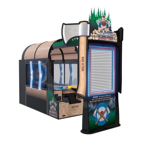
WELCOME TO AXE MASTER Congratulations on your purchase! Please take a moment to read through this manual and be sure to contact us if you have any questions, or would like more information. Thank you for your purchase! Your business is important to us and we hope... -
Page 5: Game Specifications
GAME SPECIFICATIONS WEIGHT POWER REQUIREMENTS NET WEIGHT 1829 lbs. 830 kg INPUT VOLTAGE 100 to 120 220 to 240 SHIP WEIGHT 1979 lbs. 898 kg RANGE INPUT FREQUENCY GAME DIMENSIONS 60 Hz 50 Hz RANGE WIDTH 64 inches 162.5 cm DEPTH 185 inches 470 cm... -
Page 6: Game Set Up
AXE MASTER SETUP The game will arrive on 3 pallets with many parts. Please inspect the pallets for shipping damage and report immediately to the freight company if any damage found. There will be about 5 hours of assembly time needed. - Page 7 AXE MASTER SETUP From the large middle cabinet pallet: Remove the parts stacked on the middle cabinet and set aside. Remove the 2 bolts holding the middle console to the pallet using a 9/16” wrench. There is one bolt on each end of the pallet.
- Page 8 AXE MASTER SETUP Position the front console cabinet into position close to middle cabinet. Snip plastic wire ties holding cables carefully to avoid cutting wires. Connect wires on the right side: CE29000 to CE29002 CE29004 to CE29006 Middle CE29055 to CE29056...
- Page 9 AXE MASTER SETUP Locate the front plexi guard and install into notch with “V” notch pointing upward. Ensure it sits fully down into the notch. Locate piece L - the front right side upright. (Part # AACA29056) The will be a cable inside the groove - connect this cable with the cable coming up from the lower front console cabinet.
- Page 10 AXE MASTER SETUP Locate piece K - the front left side upright. (Part # AACA29057) The will be a cable inside the groove - connect this cable with the cable coming up from the lower front console cabinet. (CE29070 to CE29069) The wire colors should match up across the connectors.
- Page 11 AXE MASTER SETUP Prep left side cage for installation. Locate left side cage assembly - (Labeled 1) Part # AAME29000-L The LED light must point toward the rear of the cabinet.. Locate Left upper cage support wood - (Labeled M) Part # WACA29059 Ensure it has the “L”...
- Page 12 AXE MASTER SETUP Prep right side cage for installation. Locate right side cage assembly - (Labeled 2) Part # AAME29000-R The LED light must point toward the rear of the cabinet. Locate right upper cage support wood - (Labeled N) Part # WACA29043 Ensure it has the “R”...
- Page 13 AXE MASTER SETUP Install the left and right cage assemblies onto the cabinet: Using 2 people, lift the right side cage up onto the cabinet. Important: Make sure the center cable is pushed under the cage and into the cabinet.
- Page 14 AXE MASTER SETUP Install the white plastic arrow lights onto the outside of the cabinet. Locate 2 of left side cage lights - (Labeled H) Part # AALI29000-L The arrow shape must point toward the front of the cabinet, with a cable coming out of the bottom.
- Page 15 AXE MASTER SETUP After all 4 white plastic arrow lights are installed onto the outside of the cabinet, install the black plastic blocks to hide the wires. Carefully climb inside the cabinet Making sure the wires are connected, feed the excess cable length back down into the hole.
- Page 16 AXE MASTER SETUP Locate the Double Middle Arch- (Labeled F) Part # AAAR29005 Place this double middle arch on the cabinet as shown. Install so the bolt threads are pointing toward the back of the game so they are not visible to the player.
- Page 17 AXE MASTER SETUP Install the roof supports: Locate the 3 of Black Plastic Roof Supports- (Labeled G) Part # AACA29096 These roof supports will have small L brackets attached. The monitor housing has small cutouts in the surface. The notched end of the roof support must slide into this notch completely.
- Page 18 AXE MASTER SETUP Slide in the roof panels: Locate the 2 Roof Panels Part # AADE29005 There are grooves in the sides of the arches - Slide the roof panel into this grove and continue pushing up and around the arch.
- Page 19 AXE MASTER SETUP Install the square metal connector plates at the top left and right edge of the wood piece as shown. 4 of the black ¼-20 X 1 Phillips head bolts using a # 3 Phillips Head bit. 2 per bracket.
- Page 20 AXE MASTER SETUP Attach Left and Right Pole Assemblies to the Safety Wall: Locate both of the Pole Assemblies. They look similar, but the left one has a 3 wire plug (Red, Yellow, Black) (Label 3) (Part # AAME29019-L) The right one has a 2 wire plug (Yellow, Black)
- Page 21 AXE MASTER SETUP The safety cage can now be lifted and aligned to the main game cabinet. Use 2 or more people to lift and move the safety cage wall. Position the right pole close to the front main cabinet and connect the 2 wire (Yellow, Black) plugs together (CE29063 to CE29062) and feed the connected wires back down into hole.
- Page 22 AXE MASTER SETUP Locate both of the black plastic wire covers. The left cover (Label 7) (Part # WACA29081) The right cover (Label 8) (Part # WACA29082) On the left side of the safety wall, connect the 2 connectors together CE29071 from the pole to CE29072 from the marquee.
- Page 23 AXE MASTER SETUP Locate both of the large axe assemblies: The left axe (Label O) (Part # AAAX29000-L) The right axe (Label P) (Part # AAAX2900-R) Locate 8 each of the hardware needed for mounting axes. (4 per side) Black ¼-20 X 1 1/2” Phillips head bolts and 2 of 1/4” black washers and a nut.
- Page 24 AXE MASTER SETUP MONITOR - DOUBLE ARCH HOUSING Part # AAAR29005 - LEFT UPPER - SINGLE ARCH CAGE SUPPORT Part # AAAR29000 ROOF PANEL Part # WACA29059 Part # AADE29005 - RIGHT SIDE CAGE LIGHTS (2) Part # AALI29000-R - SHORT...
- Page 25 AXE MASTER SETUP - RIGHT POLE ASSY Part # AAME29019-R P - RIGHT AXE ASSY - LEFT POLE ASSY Part # AAAX29000-L Part # AAME29019-L MARQUEE ASSEMBLY - LEFT AXE ASSY - RIGHT WALL WIRE COVER Part # AAAX29000-L Part # WACA29082...
-
Page 26: How To Play
HOW TO PLAY Choose a side and insert your credits; The conveyor will start to deliver axes. Wait for a partner to join, or play solo! Follow instructions on screen to throw hatchets. Throw axes and try to stick them into the target area. -
Page 27: Card Swipe Installation
CARD SWIPE SYSTEM INSTALLATION The Axe Master game is pre-wired with a UCL (Universal Card Link) connector to accept Card Swipe systems from many different manufactures. Please follow these instructions to make full use of this capability. Option #1: Card swipe systems may come with a standard 9 pin Molex connector. -
Page 28: Main Menu Functions
MAIN MENU FUNCTIONS The Menu and Menu Select buttons are located inside the left player‘s coin door. Hold the MENU button down for 1 second to open the main menu on the display. Press MENU to scroll through the options, and MENU SELECT to change the settings. - Page 29 AUDIO / ATTRACT SETTINGS MENU Scroll through the options by pressing the “MENU” button. Change selection with the “SELECT” button. Scroll to “BACK” and press the “SELECT” button to go back to the main menu. Default settings are highlighted in yellow below. Attract Audio Change selection with the “SELECT”...
- Page 30 PAYOUT SETTINGS MENU Scroll through the options by pressing the “MENU” button. Change selection with the “SELECT” button. Scroll to “BACK” and press the “SELECT” button to go back to the main menu. Default settings are highlighted in yellow below. Credits Required Tap Card Swipe Card Free Game...
- Page 31 PAYOUT SETTINGS Scroll through the options by pressing the “MENU” button. Change selection with the “SELECT” button. Scroll to “BACK” and press the “SELECT” button to go back to the main menu. Default settings are highlighted in yellow below. Winner Tickets …...
- Page 32 GAME SETTINGS Scroll through the options by pressing the “MENU” button. Change selection with the “SELECT” button. Scroll to “BACK” and press the “SELECT” button to go back to the main menu. Default settings are highlighted in yellow below. Game Mode Redemption Amusement “Redemption”...
- Page 33 GAME SETTINGS CONTINUED Scroll through the options by pressing the “MENU” button. Change selection with the “SELECT” button. Scroll to “BACK” and press the “SELECT” button to go back to the main menu. Default settings are highlighted in yellow below. No Target Point Value Used for scoring: This point value will be awarded if an axe doesn’t even hit the playfield target.
- Page 34 CAMERA CALIBRATION MENU Scroll through the options by pressing the “MENU” button. Change selection with the “SELECT” button. Scroll to “BACK” and press the “SELECT” button to go back to the main menu. The following 4 options are for fine-tuning only. Please use the “Auto Calibration”...
- Page 35 CAMERA CALIBRATION MENU Scroll through the options by pressing the “MENU” button. Change selection with the “SELECT” button. Scroll to “BACK” and press the “SELECT” button to go back to the main menu. Default settings are highlighted in yellow below. Auto Calibrate Follow these instructions before selecting “Auto Calibrate”...
- Page 36 GAME STATISTICS MENU Scroll through the options by pressing the “MENU” button. Change selection with the “SELECT” button. Scroll to “BACK” and press the “SELECT” button to go back to the main menu. Total Games Played - Shows the total number of games played. (2 player games count as 1 game) Classic Games Played - Shows the total number of Classic game modes played.
- Page 37 GAME DIAGNOSTIC MENU Scroll through the options by pressing the “MENU” button. Change selection with the “SELECT” button. Scroll to “BACK” and press the “SELECT” button to go back to the main menu. Cycle Actuator: Press Menu Select to cycle the target actuator backward and forward. Actuator Backward: Press Menu Select to move the target actuator to the back position.
-
Page 38: Estimated Ticket Payout
ESTIMATED TICKET PAYOUT The following table shows the menu settings based on 2 players playing. It is recommended to try to give a 30 - 35 percent payout on the game to keep players playing. This table shows estimated ticket payout and percent payout based on a 1 cent ticket. Alter settings if your ticket value is lower or higher. -
Page 39: Circuit Board Layout
Rear Power Supply AACE29011 Power to Motherboard Location CB8001-HH There are 2 different versions of motherboards that work with Axe Master. Refer to the next page (Motherboard Layout) for more information. AACE29033 Power to Left Door Board AACE29061 Marquee Lights... -
Page 40: Motherboard Layout
MOTHERBOARD LAYOUT There are 2 different versions of motherboards that work with Axe Master. Power Cable to The original MB12 motherboard used either: SATA Hard Drive a SATA Hard Drive a M.2 Hard Drive AAHD1900-HH SATA Hard Drive Power In... -
Page 41: Wiring Diagrams
WIRING DIAGRAM RIGHT SIDE Coin Switches and Lights AACBL4A-DOORA 4-5 VDC normally on switches. Goes to 0 when activated. To 12 Volt DC Bill Acceptor A5AC9101 or A5AC9094 AACE29023 Blue & Black Wires: 5 VDC when notch opto AACE29014 is blacked. 0 VDC when sees a notch. White &... - Page 42 WIRING DIAGRAM LEFT SIDE Coin Switches and Lights AACBL4A-DOORA 4-5 VDC normally on switches. Goes to 0 when activated. To 12 Volt DC Bill Acceptor A5AC9101 or A5AC9094 AACE29022 Blue & Black Wires: 5 VDC when notch opto AACE29014 is blacked. 0 VDC when sees a notch. White &...
- Page 43 COMMUNICATION WIRING DIAGRAM Monitor A5MO0032B A5CORD290001 3’ HDMI Cable Monitor Housing Rear Section Connection HDMI Cable is brought from the back of the middle cabinet, up to Rear Section the top of the rear cabinet. Middle Section A5CORD29000 15’ HDMI Cable Middle Section HDMI Cable is brought from the Front Console...
- Page 44 AXE EJECTOR MOTOR WIRING DIAGRAM For games manufactured before July 2022 Actuator Limit LED’s: LED’s are ON if not blocked by peg. LED’s are OFF when peg is blocking. A5PS29000 24 VDC Power Supply AAAC29002 Ejector Motor Actuator AACE29001 To AC Splitter AACE29027 AACE29030 Important!
- Page 45 AXE EJECTOR MOTOR WIRING DIAGRAM For games manufactured after July 2022 Actuator Limit LED’s: AACE29030 LED’s are ON if not blocked by peg. LED’s are OFF when peg is blocking. A5CT29000 Controller for Motor AAAC29002 Ejector Stepper Motor Actuator A5PS29000 24 VDC Power Supply AACE29068...
- Page 46 CONVEYOR MOTOR WIRING DIAGRAM For games manufactured before July 2022 A5PS29000 24 VDC Power Supply To Ground Stud in the Back Cabinet AACE29001 To AC Splitter AACE29053 AACE29028 Rear Section Middle Section Important! Dipswitches must be set this way AACE29018 AACE29029 A5CT29001 Conveyor Control...
- Page 47 CONVEYOR MOTOR WIRING DIAGRAM For games manufactured after July 2022 A5PS29000 24 VDC Power Supply To Ground Stud in the Back Cabinet AACE29053 AACE29001 To AC Splitter AACE29028 Rear Section Middle Section Important! AACE29018 Dipswitches must be set this way AACE29029 AACB29001 Conveyor Filter Board...
- Page 48 POWER DIST BOARD WIRING DIAGRAM A5PS29000 24 VDC Power Supply AACE29057 Back Section Middle Section AACE29056 Middle Section Front Console On/Off Rocker Switch on Power Supply AACE29055 Note: Newer games A5PS1021 have a hard drive Power Supply instead of a SATA drive AAHD1900-HH SATA Hard Drive...
- Page 49 BUTTON WIRING DIAGRAM Yellow Brown Purple Black Yellow Yellow Yellow Green Green White Blue Orange Black Black Black Yellow Brown Important: Do not short Light Wires to anything. Pink Switches wired Normally Open Black AACE29010 Power In from Power AACE29042 Dist Board Cable to Switches AACB29000...
- Page 50 PROTECTION WALL WIRING DIAGRAM Note: Back Wall LED lights have changed in July, 2022 Follow diagram to order the correct parts for your game. For games For games built after built before July, 2022 July, 2022 From CB8001 From CB8001 Light Board Light Board From Power...
- Page 51 GAME LIGHTING WIRING DIAGRAM For games manufactured after July 2022 AACE29077 Lights behind Target Area AACE29075 Rear Section Middle Section Left Side Arrow LED’s Right Side Arrow LED’s AACE29074 AACE29044 AACE29044 AACE29044 AACE29044 AACE29048 AACE29048 Side Cage Side Cage Stick Light Stick Light AACE29017 AACE29060...
- Page 52 GAME LIGHTING WIRING DIAGRAM For games manufactured before July 2022 AACE29045 Lights behind Target Area AACE29032 Rear Section Middle Section Right Side Arrow LED’s Left Side Arrow LED’s AACE29048 AACE29048 AACE29019 AACE29044 AACE29044 AACE29044 AACE29044 Side Cage Side Cage Stick Light Stick Light AACE29017 AACE29060...
- Page 53 SOUND WIRING DIAGRAM AACE29040 Speaker Speaker AACE29040 AACE8811 AACE8811 3.3 Ohms 3.3 Ohms Rear Section Middle Section AACE29039 Middle Section Front Console AACE29037 Speaker Speaker AACE8811 AACE8811 AACE29037 3.3 Ohms 3.3 Ohms A5CEAU010 AACE29038 AACB9600A Audio Amplifier AACE29012 A5CEAU010 AACB9600A Audio Amplifier Note: If your motherboard looks different, it is a MB13 Motherboard.
- Page 54 AC POWER IN WIRING DIAGRAM Monitor Power Cord is If the supply cord is attached to A5MO0032B damaged, it must be monitor replaced by a special cord or assembly available from the manufacturer or its Monitor Housing service agent Rear Section Power In Cord From Wall A5CORD5...
-
Page 55: Motherboard Differences
MB13 MOTHERBOARD DIFFERENCES Axe Master games can use 2 different motherboards. The MB12 was the original motherboard. During March, 2023 - the MB12 motherboard became obsolete and was changed to an MB13. These are the main differences: Difference # 1: The additional power supply connection is 8 pins instead of 4 pins. -
Page 56: Troubleshooting Guide
TROUBLESHOOTING GUIDE Troubleshooting Strategy Use common sense and a systematic method of troubleshooting to determine the exact problem, probable cause and remedy. Use the process of elimination to find the faulty component. Always check for the simple and obvious causes first such as unplugged, loose or broken wires and bad sensors, bent, pinched, stuck or jammed components. - Page 57 TROUBLESHOOTING GUIDE Problem Probable Cause Remedy Game not coining up Look for communication and Refer to “I/O Aux Board Issue” power on the I/O Aux Board diagnostic section. Enter Diagnostic Mode to see for that player. if Credits Increment when coin is inserted.
- Page 58 TROUBLESHOOTING GUIDE Problem Probable Cause Remedy Opto Sensor on ticket Blow dust from sensor and clean with Tickets do dispenser dirty. isopropyl alcohol. not dispense Faulty ticket dispenser. Replace with working dispenser to isolate the or Wrong Tickets on problem. (A5TD1) amount monitor does dispensed.
- Page 59 TROUBLESHOOTING GUIDE Problem Probable Cause Remedy Monitor HDMI cable unplugged. There are 2 cables that are connected together - A5CORD29000 and A5CORD29001 Screen shows Faulty or loose RAM “No Signal Large power connector unplugged on motherboard Input” Small power connector unplugged on motherboard Note: Motherboard will Faulty power supply -...
-
Page 60: Axes Not Scoring
AXES NOT SCORING The axe scoring is accomplished by using a 3D camera which is located behind the front console. It keys off the green color of the axe head. Gently clean the lens of the camera. If the scoring is off, the adjustment is located Camera inside the menu system. -
Page 61: Axes Not Ejecting
AXES NOT EJECTING The axe ejecting is accomplished by sliding the playfield pins out the back of the playfield grate assembly. The axes will fall down onto the conveyor belt. Troubleshooting Tips: The Ejector Motor comes with 2 sensors mounted to the top of the actuator. These sensors will tell the motor when it has come to the limit of travel. -
Page 62: Power Supply Diagnostics
POWER SUPPLY DIAGNOSTICS 1.) Verify AC power to game. Check power strip in front door. The rocker switch should be illuminated. 2.) Check connection to power supply. 3.) Ensure Power Supply switch is set to 115V (or 230V) (Some model power supplies may not have this) 4.) Ensure Power switch is on. -
Page 63: Bill Acceptor Diagnostics
BILL ACCEPTOR DIAGNOSTICS Note: There are many different models and brands of Bill Acceptors that are used on redemption games. Your Bill Acceptor may differ from the unit shown. Standard DBA is MEI # AE2454-U5E Part # A5AC9101 Determine if Bill Acceptor has power: Turn game ON—The bill acceptor should make noise as stacker cycles and green lights on outside bezel should flash. -
Page 64: Dipswitch Settings
DIPSWITCH SETTINGS Dipswitches must be set correctly on the I/O Aux Boards or game will not know which is left or right player. Turn off game by flipping the power switch on the power strip. Set dipswitches as shown: Left Side (Blue Player) Right Side (Yellow Player) Both switches 1 and 2 should be set to OFF Set switch 1 to ON , Set switch 2 to OFF... -
Page 65: How To Replace Target Pins
HOW TO REPLACE TARGET PINS The target pins may break over time, to replace: Unplug the game from the wall outlet. Unlock and remove the back door of the game. Remove the 30 screws in the black plastic panel using a Phillips screwdriver. -
Page 66: How To Replace Monitor
HOW TO REPLACE MONITOR It is best to bring the monitor housing down from the top of the game to replace the monitor while working on a bench. Unplug the game from the wall. Remove the monitor housing from the cabinet by removing the 2 bolts/washers/ Unplug the power cord Unplug the HDMI cable... -
Page 67: How To Tension Conveyor
HOW TO TENSION CONVEYOR The fabric on the conveyor will stretch over time. If the conveyor belt starts slipping or stops completely, follow these steps to re-tension the belt. Tools needed: 14mm socket There will tensioning mechanisms on both sides of the front of the belt. -
Page 68: How To Replace Conveyor Motor
HOW TO REPLACE CONVEYOR MOTOR The conveyor motor is the roller toward the rear of the conveyor belt. If the conveyor roller motor needs to be replace, follow these steps. Tools needed: # 2 Square bit 10mm Wrench 14mm Wrench Step # 1 Unplug the game from the wall. - Page 69 HOW TO REPLACE CONVEYOR MOTOR Step # 7 From the other side of the roller motor, remove the roller from the bracket. It is spring loaded, push a small screwdriver into this hole and depress the spring loaded pin. Lift this right side up as you remove the roller from the left side.
-
Page 70: How To Change Software On Mb12
HOW TO CHANGE SOFTWARE ON MB12 Axe Master games can use 2 different motherboards. This MB12 is the original motherboard. During March, 2023, this motherboard became obsolete and was changed to an MB13. These instructions will detail how to change software on the MB12. -
Page 71: How To Change Software On Mb13
HOW TO CHANGE SOFTWARE ON MB13 Axe Master games can use 2 different motherboards. The MB12 was the original motherboard which became obsolete and was changed to an MB13 during March 2023. This is the MB13 motherboard These instructions will detail how to change software on the MB13. -
Page 72: Decal Diagram
DECAL DIAGRAM Not Visible: A5DE29030 Pinch Point Warning Decal... - Page 73 DECAL DIAGRAM...
-
Page 74: Parts List
4" Black Tie, 24 Per Game W5HG1040 Hinge,8-3/8"Single Bend, 2 Per Game AACE29005 Back Ground Stud To Middle AACE29006 Middle Ground Stud, Axe Master W5KE5000 Keeper, Lock, 9 Per Game AACE29007 Right Coin Door Hinge Ground W5TM4002 T-Molding,7/8" Blue, 61 Ft Per Game... - Page 75 Front Speakers Power A5DE28528-1 Decal, Front Lower Surround, Axe Master AACE29038 Back Speaker Power from Front A5DE28528-2 Decal, Front Left Ticket Door, Axe Master AACE29039 Back Speaker Power from Middle A5DE28528-3 Decal, Front Lower Access Door, Axe Master AACE29040 Back Speaker Power...
-
Page 76: Parts Pictures
Mother Board with Hard Drive AACB29002 Stepper Actuator Filter, Post July 2022 AAHD0032-AXM Axe Master Hard Drive AACB5156 Power Dist. Board Washington State Axe Master SATA Drive AAHD0032-AX-WA AACB8001-HH Light Driver Board A5AC9101 12 Volt Dollar Bill Acceptor PARTS PICTURES... - Page 77 PARTS PICTURES A5PL9998 AABK1013 A5CBL5900 A5CE2300 A5CE6602 A5CEAU010 A5CORD1 A5CORD13000 A5CORD29000 A5CORD29001 A5CORD5 A5CORD5001 A5CORD5003 A5OU5000 A5SP10001 A5SP29000 A5SP4100 AACE1710 AACE1715 AACE29000 AACE29001 AACE29002 AACE29003 AACE29004 AACE29005 AACE29006 AACE29007 AACE29008 AACE29010 AACE29011 AACE29012 AACE29013 AACE29014 AACE29015 AACE29071 AACE29016 AACE29069 AACE29017 AACE29018 AACE29019 AACE29074 AACE29020 AACE29021 AACE29022 AACE29023 AACE29024 AACE29025 AACE29026 AACE29027 AACE29028 AACE29029 AACE29030 AACE29031 AACE29032 AACE29075 AACE29033 AACE29034 AACE29035 AACE29036 AACE29073 AACE29037 AACE29038...
- Page 78 PARTS PICTURES AACE29039 AACE29040 AACE29041 AACE29042 AACE29043 AACE29076 AACE29044 AACE29045 AACE29077 AACE29046 AACE29047 AACE29048 AACE29049 AACE29050 AACE29051 AACE29052 AACE29053 AACE29054 AACE29055 AACE29056 AACE29057 AACE29058 AACE29070 AACE29059 AACE29060 AACE29061 AACE29062 AACE29063 AACE29064 AACE29065 AACE29066 AACE29072 AACE29068 AACE29067 AACE29078 AACE8811A A5CBL4A-DOOR AACO1000 AAPB2700A A5DE0042 A5DE23021...
- Page 79 PARTS PICTURES A5DE28528-1 A5DE28528-2 A5DE28528-3 A5DE28528-4 A5DE29002 A5DE29003 A5DE29004 A5DE29005 A5DE29006 A5DE29007 A5DE29007-1 A5DE29012 A5DE29013 A5DE29014 A5DE29015 A5DE29016 A5DE29017 A5DE29018 A5DE29021 A5DE29022 A5DE29023 A5DE29024 A5DE29025 A5DE29028-1 A5DE29028-3 A5DE29029 A5DE29030 A5PT29000 A5PT29001 A5VF4604 AATA29000 A5PL29000B A5PL29001B A5PL29002B WACA29061 AASW200...
- Page 80 PARTS PICTURES A5CV29000 A5MO29001 A5PU29001 A5BE29001 A5CT29001 A5TD1 A5FI9011 A5CM29000 A5MO0032B AAAC29002 AACB15001 AACB29000 AACB29001 AACB29002 AACB5156 AACB8001-HH AACB9605-CBL AACB9600A A5CT29000 A5PS1013 A5PS29000 AAMB12-HD/AXM AAHD0032-AXM A5AC9101 AAMB13-HD/AXM...
-
Page 81: Maintenance Log
REPAIR/MAINTENANCE LOG If you need to make repairs or order replacement parts it is a good idea to keep a log. Below is a chart you can use to track repairs and maintenance. DATE MAINTENANCE PERFORMED PARTS ORDERED MISC. NOTES... -
Page 82: Technical Support
TECHNICAL SUPPORT Excellent customer service is very important to Bay Tek Entertainment! We know that keeping your games in great operating condition is important to your business. When you need us, we are here to help. You can call us for free technical assistance, and you can count on us to have parts on-hand to support your game.
Need help?
Do you have a question about the AXE MASTER and is the answer not in the manual?
Questions and answers
We have a version of axe master at my work, and every morning it boots itself up in "show mode". We are able to cold power cycle it to get it out of that mode, but is there anything i can check to try to prevent it from booting up in "show mode" every day?