Table of Contents
Advertisement
Quick Links
Manual
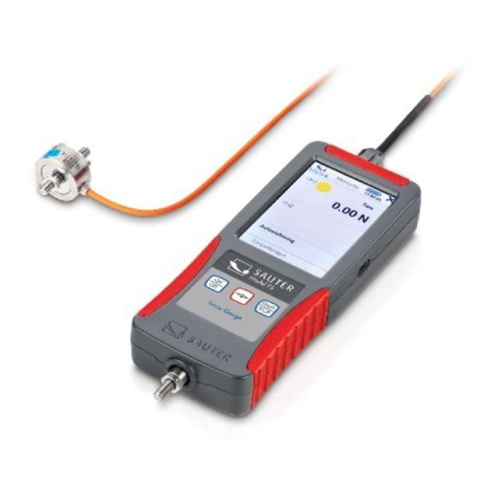
SAUTER FS
V. 1.0
01/2022
EN
Measuring channel
CH4 (optional)
Measuring channel
CH3 (optional)
Sauter GmbH
Ziegelei 1
D-72336 Balingen
E-mail: info@kern-sohn.com
Tel. : +49-[0]7433- 9933-0
Fax: +49-[0]7433-9933-149
Internet: www.sauter.eu
Measuring channel CH2
Measuring channel CH1
Interface socket
(optional)
FS-BA-en-2210.docx
Advertisement
Table of Contents

Related Manuals for sauter FS Series


Summary of Contents for sauter FS Series
- Page 1 Sauter GmbH Ziegelei 1 Tel. : +49-[0]7433- 9933-0 D-72336 Balingen Fax: +49-[0]7433-9933-149 E-mail: info@kern-sohn.com Internet: www.sauter.eu Manual SAUTER FS V. 1.0 01/2022 Measuring channel Measuring channel CH2 CH4 (optional) Measuring channel CH1 Interface socket Measuring channel (optional) CH3 (optional) FS-BA-en-2210.docx...
-
Page 2: Table Of Contents
Congratulations on your purchase of a digital force gauge with internal or external measuring cell from SAUTER. We hope you enjoy your quality measuring device with its wide range of functions. If you have any questions, requests or suggestions, please do not hesitate to contact us. - Page 3 Prepare measurement ................. 12 Switch on ..........................12 Activate display with activated energy saving options ............12 Measuring with internal sensor .................... 13 Measuring with external sensors ..................13 Plugging in and unplugging external sensors ..............13 Measurement ....................13 10.1 Start screen ..........................
- Page 4 Power supply ....................27 14.1 Charging the battery ......................27 14.2 Plug-in power supply unit ..................... 28 14.3 Power supply via PC ......................28 Interface ......................28 15.1 Interface description ......................28 15.1.1 USB ............................28 15.2 Interface protocol ........................28 Declaration of conformity ................
-
Page 5: Introduction
Read these operating instructions carefully before commissioning, even if you already have experience with SAUTER measuring devices. SAUTER offers the software and accessories as an option to make the measuring device more versatile in use. Please enquire with SAUTER or your SAUTER dealer or visit our website at www.sauter.eu. -
Page 6: Risk Of Accident
4.3 Risk of accident Observe the national accident prevention regulations. Incorrect use of the equipment can lead to serious injuries, death, property damage and personal injury. Use may only be carried out by trained and experienced personnel. Never load load cells and force gauges beyond the Emax range (nominal load, max. capacity) of the sensor used. -
Page 7: Maximum Measuring Range
4.6 Maximum measuring range Never load the unit beyond the maximum measuring range! The max. measuring range of your unit with internal measuring cell can be found on the type plate on the back of the unit! The maximum measuring range of external sensors can be found on the type plate on the sensors! Overloads are signalled by a warning tone when the signal tones are activated. -
Page 8: Scope Of Delivery
6 Scope of delivery Force gauge FS Transport case Systainer® Touch-Pen USB C cable EU plug-in power supply unit Operating instructions 7 Connections 7.1 USB C socket Your unit is supplied with power via the USB C socket on the right-hand side of the unit and serves as an interface for data transfer to a PC. -
Page 9: Connection Sockets For External Sensors
Measuring channel (optional) CH3 (optional) You will receive the connectors when you order a sensor from SAUTER, as described in section 13.2 "" described. 7.2.1 Compatibility and necessary accessories It is recommended to purchase the sensors directly from SAUTER. There you will receive compatible sensors with the corresponding necessary services. -
Page 10: Pin Assignment Connector
7.2.3 Pin assignment connector Connection N.C. Memory chip IO Memory chip GND N.C. N.C. Supply + Input + Input - Supply + N.C. 7.3 Expansion from 2 to 4 measuring channels Each unit is factory-equipped with sockets for 4 measuring channels, even if you have purchased a variant with 2 channels. -
Page 11: Display And Measurement
8.2 Display and measurement 3.5" touch screen Standard version with 2 or 4 measuring channels for external force sensors (subsequently expandable from 2 to 4) An internal measuring cell is possible (will be deactivated if slot 1 has a external measuring cell is plugged in) Suitable for 4-wire and 6-wire sensors with strain gauges up to 3mV/V Bridge supply voltage 6V High resolution: up to 10000 points per measuring channel... -
Page 12: Fastening Option
8.4 Fastening option The unit can be attached to test stands, fixtures and handholds (AFK 02 is available as an option) using M3 screws at the four threaded holes on the rear: 9 Prepare measurement 9.1 Switch on Press and hold the ON/OFF button for approx. 3 sec. 9.2 Activate display with activated energy saving options If you have activated the energy-saving mode of the display as described in section 11.1.3 it is possible that your unit is switched on and only the display is switched off. -
Page 13: Measuring With Internal Sensor
9.3 Measuring with internal sensor For units equipped with an internal sensor (not FS 2 and FS 4), the internal sensor is displayed as channel 0 (CH0) when you click on the "Measurement" function. If an external sensor is connected, CH0 is automatically deactivated and the external channels are displayed instead. -
Page 14: Start Measurement
10.2 Start measurement Click on Measurement on the touch screen 10.3 Initialise measuring channels Press the START/STOP button to display the measured values of the connected sensors. 10.4 Tare measuring channels 10.4.1 Channel single To set a single channel to zero, click with the touch pen on →0"" to the right of the displayed channel. -
Page 15: Main Menu Settings
The forces on the FS encoder must always be applied in the axial direction of the load application bolt. Avoid transverse forces. These cause measurement errors and can damage the sensor. Ideal force application Incorrect force application wrong ideal ideal wrong wrong ideal... -
Page 16: Menu Unit Settings
Main menu Device settings Measurement settings Sensor settings Internal memory Clicking on or takes you to the previous page. Press the ON / OFF button to return to the start screen. 11.1 Menu unit settings Device Language Date / Time Energy saving options Display Audio... -
Page 17: Select Language
11.1.1 Select language Select your desired language: Menu Device settings→ Language→ 11.1.2 Set time and date Menu Machine Settings→ Date →/ Time Click on "Change" with the touch pen and set the current time and date with the arrows. Save the entered values by clicking on "OK". 11.1.3 Set energy saving options Menu Machine Settings→... -
Page 18: Switching Tones On And Off
11.1.5 Switching tones on and off Menu Unit→ settings Switch tones→ on and off 11.1.6 Service Menu Unit Settings→ Service→ 11.1.6.1 Display raw data Switch here to display the raw measured values during adjustment as AD value or as voltage in mV. 11.1.6.2 Reset unit Do not use this function! Contact the service department! 11.1.7 Device info... -
Page 19: Readability
11.2.1.2.2 For short time measurements Such as maximum load measurement to destruction, which lasts only a few seconds choose a higher frequency. 11.2.2 Readability By clicking on change you can increase the readability by the displayed factor. The maximum resolution is n=10,000 The smallest adjustable readability for a sensor is calculated as follows: ��... -
Page 20: Functions
11.2.3 Functions 11.2.3.1 Track Measured values are displayed continuously and stored with the set sampling frequency if required. To save the readings: 1. Press the Start/Stop button 2. The measured values are now saved and the generated file name in which the data are saved appears in the display under the "Recording in progress"... -
Page 21: Channel Limits
11.2.3.3 Manual without statistics Use this mode to manually save the measured values currently displayed after initialisation at the touch of a button. 1. Press the START/STOP button. The display shows "Manual running". This value is not yet saved. 2. Each additional short press of the START/STOP button saves the currently displayed readings. -
Page 22: Sensor Settings
Select the channel on which you want to make settings. Only external channels to which a sensor is connected are displayed. Only use the plugs with memory chip fitted by SAUTER for external sensors. Force gauges and optional external sensors, as described in chapter 13.2 are delivered adjusted. -
Page 23: Calibration Data
11.3.1.3.2 Load and unload before adjustment Load and unload the unit at least 3 times with the nominal load. 11.3.1.3.3 Read in adjustment points Now read in the adjustment 11.3.1.3.1 adjustment points. When you have attached the respective adjustment weight, click on positive adjustment point and negative adjustment point in the lower area of the display. -
Page 24: Internal Memory
11.4.2 Send file If you connect the measuring instrument to a PC via an interface, you can send the selected files to the PC. The optionally available plug-in for MS Excel SAUTER AFI 2.0 is recommended for this purpose. 11.4.3 Delete file Select the files you no longer need to delete them. -
Page 25: Accessories
Further accessories can be found in the webshop www.sauter.eu 13.2 External measuring cells External sensors are available in the webshop www.sauter.eu. For each sensor you need the service corresponding to the nominal load from the following table, incl. connector and memory chip:... -
Page 26: Adjust And Calibrate
Connector for FS incl. PARAMETER MEMORY mounted on measuring cell and FS 402 two-point adjusted with weight up to 0.5kN Connector for FS incl. PARAMETER MEMORY mounted on measuring cell and FS 403 two-point adjusted with weight up to 2kN Connector for FS incl. -
Page 27: Transport Case For Accessories
"T-LOCK" fastener. 13.4 Read out stored measured values with EXCEL plug-in With the optionally available EXCEL plug-in SAUTER AFI 2.0, stored measurement data can be transferred to a PC. (EXCEL software not included in delivery!) 14 Power supply 14.1 Charging the battery... - Page 28 14.2 Plug-in power supply unit In some countries, a different plug-in power supply unit may be required for connection to the local mains supply. The adapter or plug-in power supply used must not exceed the output values at the USB output: Voltage: 5V DC Current: 1A Do not use a defective or damaged plug-in power supply! There is a danger...
Need help?
Do you have a question about the FS Series and is the answer not in the manual?
Questions and answers