Table of Contents

Subscribe to Our Youtube Channel
Related Manuals for sauter FL series


Summary of Contents for sauter FL series
- Page 1 Sauter GmbH Ziegelei 1 Tel.: +49-[0]7433- 9933-0 D-72336 Balingen Fax: +49-[0]7433-9933-149 E-Mail: info@kern-sohn.com Internet: www.sauter.eu Instruction Manual Digital Force Gauge SAUTER FL V. 1.4 11/2017 PROFESSIONAL MEASURING FL-BA-e-1714...
- Page 2 SAUTER FL V. 1.4 01/2017 Instruction Manual Digital Force Gauge Summarize: Introduction ....................3 Before Use ...................... 3 Operation Overview ..................3 Battery Indicator .................... 3 Fitting Accessories ..................3 Mounting to a Fixture or Test Stand ............. 4 Powering on ....................4 Basic Functions .....................
-
Page 3: Introduction
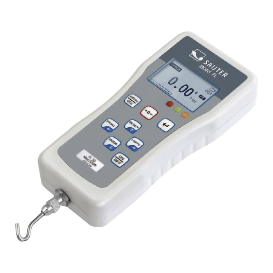
1 Introduction Thank you for choosing the SAUTER FL series instrument. With correct use and regular re-calibration it will give many years of accurate and reliable service. The FL can measure tensile and compressive forces accurately, being simply used by the operator. It may be used handheld or mounted on a fixture or test stand. -
Page 4: Mounting To A Fixture Or Test Stand
6 Mounting to a Fixture or Test Stand The four M3 thread holes on the rear of the gauge can be used for mounting the gauge to a SAUTER test stand. 4xM3 screws are included in delivery. Backside housing and dimensions of the force gauge:... -
Page 5: Basic Functions
Figure 1 To power up the gauge, the ON/OFF key has to be pressed. A short self-test will start during which the capacity in Newton will be shown. After the self test, providing no load has been applied to the instrument, the display will show all zeroes. - Page 6 A load indicator bar alerts the operator to how much load has been applied to the load sensor. For tensile force the indicator bar is moving from right to left. For compressive forces the indicator bar is moving from left to right. Zeroing the gauge During the operation of the gauge it is often necessary to zero the display –...
- Page 7 Peak-Tension mode Press MODE key until the appears on the display. The display will show the maximum tensile force. See Figure 3b Peak-Compression mode Press MODES key until appears on the display. The display will show the maximum compressive force. See Figure 3c RESET the gauge Press RESET key to clear both maximum registers and prepare for detecting the next maximum readings.
-
Page 8: Main Menu
9 Main Menu Press MENU/ESC key to access the main menu. To move between the option listed on the main menu page, press UP and DOWN arrow keys to move the cursor. Press ENTER to select the sub-menus, activate feature and enter values. Within sub- menus UP, DOWN, LEFT and RIGHT arrow keys will also change numerical values. - Page 9 key has been pressed. The AO will appear in the main display if you activate this feature. Figure 5 Use UP and DOWN key to move the cursor. Press the ENTER key to select auto-off option and return to main menu page. 2) PASS-FAIL The Pass-Fail feature used to set a defined acceptable maximum and minimum forces gap for measuring.
- Page 10 Example LOWER LEVEL = 10 N, UPPER LEVEL = 20 N Example LOWER LEVEL = 10 N, UPPER LEVEL = 20 N 3) MEMORY This is used to view the saved record, delete current record, delete all record and print data of the saved record. To access MEMORY menu, go to the main menu page press UP and DOWN to move the cursor point to MEMORY and press ENTER key the display will show the memory page.
- Page 11 You can find a detailed description of this procedure in chapter 12 at the end of this instruction manual. Take care that you need weights to adjust the force gauge. For more details, please contact your SAUTER distributor or SAUTER GmbH directly per phone (number mentioned above) or by e-mail.
-
Page 12: Measurement Practice
The FL-series have an analog output +/- 2V, In normal operation use analog values depend on the reading value of TRACK, PEAKT and PEAKC mode. If PASS-FAIL function is used analog value = 2V when PASS, and analog value = 0V when FAIL. 7) ABOUT This shows the information of your gauge (Firmware revision, Model, Capacity, Serial number). -
Page 13: Output / Output Rating / Hardware Adjustments
11.1 Output / Output rating / Hardware adjustments RS-232 and USB: - 8 data bits - 1 Start bit, 1 Stop bit - No parity - Baud rate: 9600 - Peak Capture Rate: 0.100 S - ADC Sampling Rate: 1,000 Hz 11.2 RS 232 interface occupancy 12 Adjustment procedure Introduction... -
Page 14: Fl-Ba-E
Calibration 1. Turn the gauge on 2. Go to main menu by pressing the MENU key and press the UP and DOWN key to move the cursor to point to CALIBRATION and press ENTER key, then the ENTER PASSWORD page will be displayed. ENTER PASSWORD 4 DIGIT PASSWORT : 0000... - Page 15 Press UP and DOWN to change max capacity, press and hold to scroll change. Press ENTER key to save selected and return to Calibration Menu page. 4) Tension Calibration. At the Calibration menu page, press UP and DOWN key to move the cursor to point to TENSION GAIN and press ENTER key.
- Page 16 - Apply 100% of the instrument’s capacity load onto the support(s) for compression. - Press UP, DOWN, RIGHT ARROW or LEFT ARROW key to adjust compression gain until the gauge displayed max capacity count. - Press ENTER key to store the counts for full-scale compression 6) After your successful calibration, remove any accessories, which have been mounted to the gauge and place the gauge on its back on a level surface.
Need help?
Do you have a question about the FL series and is the answer not in the manual?
Questions and answers