
Related Manuals for Digi 700 Series

Summary of Contents for Digi 700 Series
- Page 1 HI, MI, WI-700 service manual HI-700, HI-700W, MI-700, WI-700 Service manual Issue 9 04/2020...
- Page 2 COPYRIGHT – DIGI EUROPE LIMITED Published by DIGI Europe Limited All due care has been taken in the preparation of this publication, but DIGI Europe Limited accepts no liability for any inaccuracies which may be found. DIGI Europe Limited reserves the right to make changes without notice, to both this publication and the product, which it describes.
-
Page 3: Table Of Contents
HI, MI, WI-700 service manual Contents 1 - Installation About the HI-700 evo, HI-700W, MI-700 & WI-700 Shipment of machine Safety Moving the machine Rated operation conditions Programming note Installation requirements 1-10 Installation - machine feet 1-11 Fitting labeller to labeller arm 1-11 Connections inside electrical cabinet 1-12... - Page 4 HI, MI, WI-700 service manual Take-up motor 2-50 Label gap sensor 2-51 Power ON/OFF switch 2-52 Thermal head pressure (Signature) 2-52 Touch applicator - (Signature) 2-53 Blow bar 2-54 Pneumatic connections 2-55 Multijet air box - (Signature) 2-56 HS blow applicator 2-57 Base labeller belt applicator 2-60...
- Page 5 HI, MI, WI-700 service manual 4 - Servicing - continued Air cylinder position on head assembly 4-54 Label gap sensor sensitivity adjustment 4-55 Labeller electronic board (Signature & Classic) 4-58 Take-up motor torque setting 4-60 Brake arm - position & adjustment 4-61 Brake arm - setup for inside wound labels 4-63...
- Page 6 HI, MI, WI-700 service manual 6 - Maintenance schedule Maintenance schedule introduction All conveyors Scale Labeller Label applicators Side & HS blow label applicators Base label applicator Labeller lifting gear Touch screen Air regulator Pack sensors Safety 6-10 Machine stability 6-10 Inside electrical cabinet 6-10...
- Page 7 HI, MI, WI-700 service manual 9 - Machine specification HI-700 / HI-700W basic machine specification MI-700 basic machine specification WI-700 basic machine specification HI-700 dimensions - single top labeller HI-700 dimensions - top & base labeller plus infill conveyor after scale HI-700W dimensions MI-700 dimensions WI-700 dimensions...
-
Page 8: Installation
HI, MI, WI 700 service manual - 1 - Installation Installation Contents- About the HI-700 evo, HI-700W, MI-700 & WI-700 Shipment of machine Safety Moving the machine Rated operation conditions Programming note Installation requirements 1-10 Installation - machine feet 1-11 Fitting labeller to labeller arm 1-11 Connections inside electrical cabinet... - Page 9 HI, MI, WI 700 service manual - 1 - Installation About this manual This service manual contains information for a qualified service engineer on aspects of the HI-700 evo, MI- 700 & WI-700 machines such as basic & detailed maintenance, component parts and recommended spare parts.
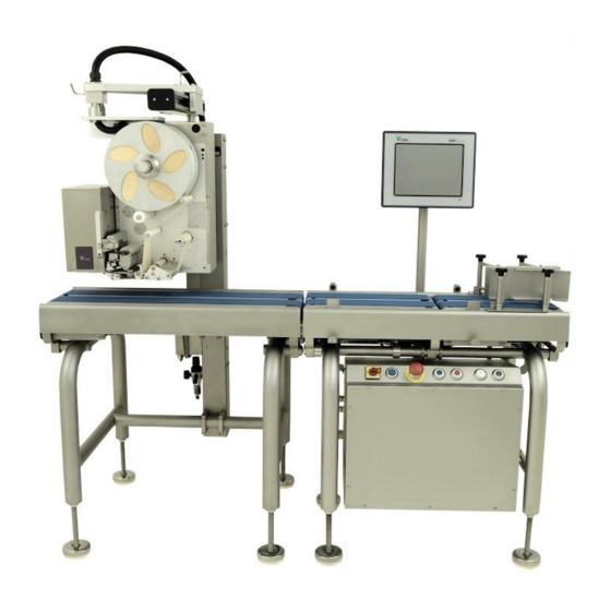
- Page 10 HI, MI, WI 700 service manual - 1 - Installation HI-700W The HI-700W has wider conveyor than the standard HI-700. These conveyors will accept a product up to 410mm wide compared to the standard HI of 250mm wide. Model shown left is with Signature labeller HI-700 evo top &...
- Page 11 HI, MI, WI 700 service manual - 1 - Installation MI-700 Touch screen The MI-700 is a PC based mid Labeller with speed weigh labeller. The applicator dynamic weighing system is capable of weighing and labelling up to 80 packs per minute, depending upon package Pack sensors...
-
Page 12: Shipment Of Machine
Shipment of machine Machines leaving Digi Europe Ltd are normally shipped in a wooden crate, and the load cell clamped by the transit / under-over load discs. These discs must be released and reset for under / over load protection before the machine is operated, see further in this section for setting details. -
Page 13: Safety
HI, MI, WI 700 service manual - 1 - Installation Safety- your responsibilities In normal operation, it is essential that the scale cover, protective covers or panels are in place. The conveyors should be fitted and in their correct place for the machine to operate. Always stop the conveyors and disconnect the mains electrical and air supplies when making adjustments, cleaning and setting the machine. - Page 14 HI, MI, WI 700 service manual - 1 - Installation Mechanical safety The machine must be operated only when placed on a flat, level and solid floor. Adjust the feet so that the machine is level and ensure that the locknut of each foot is fully tightened. Failure to comply with these points may result in the machine falling over onto an operator.
-
Page 15: Moving The Machine
Moving the machine HI, MI, WI 700 service manual - 1 - Installation When moving the machine the labeller should be supported to stop lateral movement. If moving only a short distance over a smooth surface the machine can be moved carefully to its new location with the aid of the lifting angles, supplied with the machine. -
Page 16: Programming Note
HI, MI, WI 700 service manual - 1 - Installation Rated operational conditions for HI-700 EVO, MI-700 & WI-700 Climatic environment Temperature- lower limit = 0°C Upper limit = +30°C Humidity – non-condensing environment Intended location – closed (indoors) Mechanical environment The mechanical environment classes M1, M2 &... -
Page 17: Installation Requirements
HI, MI, WI 700 service manual - 1 - Installation Installation requirements Site requirements This machine is designed to work within the normal environments associated with the food industry, i.e. humidity – non condensing environment and temperature between 0°C and +30°C. Weighing and labelling equipment is however sensitive to misuse and due care and attention should be given to the operating environment. -
Page 18: Installation Machine Feet
HI, MI, WI 700 service manual - 1 - Installation Installation Machine feet Once the machine has had any packaging removed, place the machine in its required position. With the machine in position, lower the feet. Level the machine and ensure all feet are firmly on the solid ground For a HI machine which has two... -
Page 19: Connections Inside Electrical Cabinet
HI, MI, WI 700 service manual - 1 - Installation Connections inside electrical cabinet HI-700 - The labeller conduit, power lift motor cable & conveyor safety switch wire needs to be fed into the rear of the electrical cabinet. MI-700 / WI-700—normally the labeller, power lift motor and conveyor safety switch remain connected for transportation, therefore no install connections for these cables is required. - Page 20 HI, MI, WI 700 service manual - 1 - Installation Air pipe Feed the air pipe back out of the cabinet through cable gland and connect to the air regulator. Ethernet cable The Ethernet cable needs to connected to the Ethernet switch situated under the main board. 1-13 Issue 9 04/2020...
- Page 21 HI, MI, WI 700 service manual - 1 - Installation Labeller power, power lift motor power & conveyor safety switch Conveyor safety Power lift connections Mains power - - connect connect the mains switch the power lift wires to the terminal rail lead wires to the terminal rail position circles above position circled above...
- Page 22 HI, MI, WI 700 service manual - 1 - Installation Additional information for conveyor safety switch connections The infeed and scale switches are already in place for the HI. For MI & WI, all switches are pre-connected. Connect the outfeed switch wires to the terminals to form a series electrical connection between all three conveyor safety switches scale This diagram shows a typical layout of the connections made...
-
Page 23: Outfeed Conveyor Connection
HI, MI, WI 700 service manual - 1 - Installation Outfeed conveyor motor connection There is a round 8 pin connector for the outfeed conveyor motor which needs connecting to the 8 pin connector from the electrical box, (MI & WI are already connected). The connector will have a bracket attached to it which is to be mounted on the rear side frame of the out- feed conveyor Straight bracket connector type... - Page 24 HI, MI, WI 700 service manual - 1 - Installation Additional conveyor (outfeed) before labeller(s) If the machine has an infill conveyor fitted (extra conveyor between scale and outfeed) an additional motor cable entry may be at the side of the electrical cabinet. This motor cable will be the outfeed conveyor. The infill conveyor cable will enter at the rear of the cabinet which normally has the outfeed cable.
-
Page 25: Labeller Position Adjustment
HI, MI, WI 700 service manual - 1 - Installation Labeller position adjustment Ensure that the labeller is positioned such that packs can pass underneath it, with sufficient clearance for labels to be applied. Press the up / down power lift buttons on the front of the electrical cabinet to move the labeller height up or down. -
Page 26: Load Cell Transit Screw
HI, MI, WI 700 service manual - 1 - Installation Load cell transit screw The transit screw fitted to the scale for protection during transit needs to be released and re-adjusted to act as a limit stop screw in the up and down direction. To gain access to this screw it may be necessary to remove the scale and/or the infeed conveyors NOTE: if re-tightening the under-load discs ensure the load cell is not strained in either direction. - Page 27 HI, MI, WI 700 service manual - 1 - Installation Set lower disc gap With no load on the scale conveyor, adjust the disc to obtain a 1mm gap between the disc and the under- load bottom block. Note: to keep the disc in the correct position it will be tightened against the locknut underneath it, therefore it may be necessary to adjust the position of the bolt to obtain the correct gap size.
- Page 28 HI, MI, WI 700 service manual - 1 - Installation Under and over load discs set with 1mm gap Ensure that scale conveyor motor wires and load cell cable are routed correctly to ensure correct weighing. Wires must not touch the scale body (top frame) or conveyor. The motor wires are held in the correct place by wire clips.
-
Page 29: Setting Corner Overload Stops
HI, MI, WI 700 service manual - 1 - Installation Setting corner over load stops It is important that the overload stops at each corner of the scale assembly are set correctly to help protect the load cell from being over loaded. The scale assembly has four overload stop screws, one in each corner. - Page 30 HI, MI, WI 700 service manual - 1 - Installation Electrical cabinet & display screen operation buttons Electrical power on Emergency Start & stop Up / down power isolator indicator stop switch conveyors lift for labeller switch Switching on Once the electrical plug is plugged into a suitable power supply, turn the isolator switch 90°...
-
Page 31: Loading Labels - Signature Top Labeller
HI, MI, WI 700 service manual - 1 - Installation Loading labels - Signature top labeller Inside wound or outside wound labels can be used on the label- ler. The picture shows an outside wound label roll on the labeller on a left to right top labeller Important note: the label path should always run centrally through the labeller. - Page 32 HI, MI, WI 700 service manual - 1 - Installation Feed labels over brake arm and Feed labels between label guide and through gap sensor, then pull smaller white roller (for outside through thermal head area. Tip - pull enough labels/paper through at wound labels) this point and remove labels from backing paper to allow threading to final position (take-up spool)
- Page 33 HI, MI, WI 700 service manual - 1 - Installation For inside wound label the label path uses the large web roller For inside wound labels, place the Return labels up and over the Feed labels around large web labels on the reel as above brake arm (white) roller For the remainder, feed the labels in...
- Page 34 HI, MI, WI 700 service manual - 1 - Installation Loading labels with Signature labeller fitted with centralizer option The label path for loading label is the same for the centralizer option as it is for the standard reel. The addition of the centralizer allow the labels to be easily centralized, therefore not needing to manually adjust the back plate reel as for a standard reel assembly Signature labeller fitted with centralizer option Holding the rear reel,...
-
Page 35: Loading Labels - Classic Labeller
HI, MI, WI 700 service manual - 1 - Installation Loading labels - Classic labeller To load the labels follow the route shown on the diagram and details below. Check labels are inside or outside wound and load accordingly Adjust rear spool position to allow centre of labels to run through the centre of the labeller Load labels onto spool. - Page 36 HI, MI, WI 700 service manual - 1 - Installation Lift thermal head up from the platen roller Feed labels around the white guide roller, through the label gap sensor and between thermal head and platen roller Ensure backing paper is fed behind blow Open the drive/pinch rollers and place backing paper around the drive roller Use label roll clip to secure backing paper to take...
-
Page 37: Component Parts
HI, MI, WI-700 service manual - 2 - component parts Component parts Contents- The electrical cabinet Items inside the electrical cabinet PC main board - type LV-67P Hard drive Battery Power supply LS75-15-15.8VDC UPS board 2-10 5 port Ethernet switch 2-11 Relay 5v 2-12... -
Page 38: The Electrical Cabinet
HI, MI, WI-700 service manual - 2 - component parts The electrical cabinet The electrical cabinet for the 700 machine has several outlets around the cabinet for various parts of the 700 machine to be connected into. These external connections are listed below. Rear of cabinet Infeed Motor Scale Motor... - Page 39 HI, MI, WI-700 service manual - 2 - component parts The electrical cabinet Main pc board - LV-67P Hard drive Battery Power supply 15v UPS board 5 port Ethernet switch Relays 5v A/D power supply A/D unit Power supply 24v Omron PLC Motor driver board (one for each conveyor motor) Infeed conveyor speed control...
-
Page 40: Pc Main Board - Type Lv-67P
HI, MI, WI-700 service manual - 2 - component parts PC main board - Type LV-67P Processor type - Intel® Pentium® N3710 - 1.6Ghz Memory - 4Gb DDR3 Hard drive Memory - SO-DIMM1 connection Launch button connection PC processor COM 5 & 6 DC in COM 3 &... - Page 41 HI, MI, WI-700 service manual - 2 - component parts PC main board - Type LV-67P - COM 3 & 4 A cable form plugged into the main board (COM 3 & COM 4) is attached to two DB9 connectors which are mounted beside the Ethernet switch These COM ports can be used for an additional...
- Page 42 HI, MI, WI-700 service manual - 2 - component parts PC main board - Type LV-67P - COM port 2 configuration JCSEL1, JCSEL2 : For configure COM2 communication mode Function JCSEL1 JCSEL2 RS232 RS485 RS422 JCSEL1 JCSEL2 Issue 9 04/2020...
-
Page 43: Hard Drive
HI, MI, WI-700 service manual - 2 - component parts Hard drive The standard single hard drive used is a solid state type, typically at 60Gb in size with Sata type connection. The hard drive holds the Windows® embedded standard image, the Console or Worldview operation software and programmed data such as plu’s, label formats etc. -
Page 44: Battery
HI, MI, WI-700 service manual - 2 - component parts Battery The battery is a 12v 1.2AH maintenance free sealed lead acid type. A charge is provided to it from the 15.8v power supply via the UPS board. (charge voltage approx. 15v for Pico UPS-100) The battery is used if a sudden power failure occurs. -
Page 45: Power Supply Ls75-15-15Vdc
HI, MI, WI-700 service manual - 2 - component parts Power supply 15.8v (LS75-15) This power supply supplies 15.8 volts to the UPS board which in turn transfers this voltage to the PC main board(15.8v) The input voltage (240v AC) is supplied from the terminal rail connection 15.8v power supply location LS-75-15 power supply specification Input : 100-240VAC... - Page 46 HI, MI, WI-700 service manual - 2 - component parts UPS board - Pico UPS-100 The UPS board controls the circuit for the un-interruptible power supply (UPS) . The board has a 15.8v input from the power supply LS75-15 and outputs 15.8v to the PC. The board also supplies a charging voltage to the battery via a relay of 13.5 to 15v Input voltage of 15.8v from...
-
Page 47: Port Ethernet Switch
HI, MI, WI-700 service manual - 2 - component parts 5 port Ethernet switch The 5 port Ethernet switch is the connection point for all labeller / printer that are to be connected to the machine The switch is supplied a voltage of 5v from the PC main board The Ethernet switch is powered from the ATX... -
Page 48: Relay 5V
HI, MI, WI-700 service manual - 2 - component parts Relays 5v There are two relays (both the same type) in the cabinet Relay 1 - acts as the ‘switch’ for the backup voltage (battery) to take over if the normal power fails. The relay coil is connected to the hard drive 5v supply on the PC (at relay positions A1 &... -
Page 49: A/D Power Supply
HI, MI, WI-700 service manual - 2 - component parts A/D power supply The A/D power supply supplies DC voltage of 9v and 5v to the A/D unit. Connection of 5v and 9v to A/D Along the top of the board is four LED’s. -
Page 50: A/D Unit
HI, MI, WI-700 service manual - 2 - component parts A/D unit The analogue to digital (A/D) unit is the device for converting the analogue values from the load cell (actual strain gauge bridge voltage) to a digital signal and transmitting these values (via RS232 serial) to the main board. - Page 51 HI, MI, WI-700 service manual - 2 - component parts A/D power supply connection Serial connector (9way D type) connects to main board at COM port 2. Connection to pack sensor circuit from PLC A/D Security switch To serial connection on main board A/D psu See electrical diagrams for full details of connection...
- Page 52 HI, MI, WI-700 service manual - 2 - component parts Power supply 24v - RWS300B-24 This 24v PSU supplies 24v to the contactor / conveyor stop – start circuit and the four cooling fans within the cabinet. Refer to electrical drawing for exact route of connections. •...
-
Page 53: Omron Plc
HI, MI, WI-700 service manual - 2 - component parts Omron PLC The PLC unit consists of 3 units, the power unit (PA201), the PLC unit (CPM2C 20CDTC-D) and the analogue I/O unit (MAD11). The PLC deals with input and output signals to and from various parts of the 700. E.G – pack sensors, conveyor speed, reject signal. - Page 54 HI, MI, WI-700 service manual - 2 - component parts PLC unit CPM2C Refer to the electrical drawings for more details on the connection to and from this unit. Serial connec- tion to pc main board Red=24v term rail To speed control Yellow=start button board - run/brake White=stop button...
- Page 55 HI, MI, WI-700 service manual - 2 - component parts MAD11 analogue unit Refer to the electrical drawings for more details on the connection to and from this unit. To Motor speed control boards Green to VRM Orange to VRL Note: infeed output goes through a 2K5Poteneometer for separate speed adjustment used...
-
Page 56: Motor Driver Board
HI, MI, WI-700 service manual - 2 - component parts Motor driver board Each conveyor is powered by a brushless DC motor fitted with gearhead, controlled by a AXHD50K motor driver. The driver is illustrated below. There is a motor driver board for each conveyor fitted to the machine. In the main electrical cabinet the infeed, scale &... - Page 57 HI, MI, WI-700 service manual - 2 - component parts Motor driver board Black Black Blue Purple 2-21 Issue 9 04/2020...
- Page 58 HI, MI, WI-700 service manual - 2 - component parts Conveyor direction The direction of running for each conveyor is controlled by the connection/disconnection of pin 9 (CW/ CCW) of CN2 on the driver board. The connection/disconnection of this contact is made by the small Molex plug / socket near to this position on the driver board.
-
Page 59: Infeed Speed Control
HI, MI, WI-700 service manual - 2 - component parts Infeed conveyor speed control As default the infeed, scale and outfeed conveyors will run at the same speed (the speed the machine is set for selected plu or set on operation screen). Depending on the spacing between packs on entering the infeed, it may be necessary to reduce the speed of the infeed conveyor compared to the scale and outfeed. -
Page 60: Primary Fuse
HI, MI, WI-700 service manual - 2 - component parts Primary fuse - 10A The machine is protected at the incoming mains supply with a primary fuse rated at 10A. The location of this is as shown below. To replace the fuse, unclip the front of the fuse holder with a flat bladed screw driver (1/4 turn anticlockwise) and remove the front of the holder and fuse. -
Page 61: Cooling Fans
HI, MI, WI-700 service manual - 2 - component parts Cooling fans There are 4 fans which circulates the air within the cabinet Ensure these fans are kept clean, not obstructed and functional at all times the machine is powered on. Four of these fans, connected to the 24v pow- er supply Software licence dongle... -
Page 62: Pack Sensors
HI, MI, WI-700 service manual - 2 - component parts Pack sensors The two pack sensors mounted across the infeed & scale conveyors are a fibre optic type or an optoelectronic retro reflective type sensor. An overhead mount version is also available. Fibre optic sensor (Omron E3X-NA11) The sensor amplifiers are located inside the control box and need to be adjusted to the correct sensitivity in order to detect packs. - Page 63 HI, MI, WI-700 service manual - 2 - component parts Optoelectronic retro reflective type sensor. (Wenglor KR87NCT2) This sensor is mounted across (standard fitment) or overhead the infeed and scale conveyors. The sensors are supplied 24v from the 24v terminal rail inside the control box Inside the electrical cabinet the incoming Wenglor sensor cable has wires coloured Brown (+24v)
- Page 64 HI, MI, WI-700 service manual - 2 - component parts Conveyor & motor (click in type conveyor) Removal of conveyors from machine. Each conveyor is located in the frame of the machine by pins in the side frame. To lift any one of the conveyors out, place hands under conveyor belt at the spring load end of the conveyor and lift upwards, this will release the conveyor from the pins.
- Page 65 HI, MI, WI-700 service manual - 2 - component parts Conveyor (click in type conveyor) Double sided drive belt Idler roller Drive roller Standard split type con- veyor belts. Can be a solid belt, de- pending on machine type and specification required Conveyor belt removal With the conveyor out of the machine frame, compress the spring loaded end and lock it into the com- pressed position.
-
Page 66: Outfeed Conveyor When Base Labeller Is Fitted
HI, MI, WI-700 service manual - 2 - component parts Outfeed conveyor when base labeller is fitted The outfeed conveyor (first long outfeed) connects to the machine frame in a different way to the other conveyors and therefore the way it can be removed differs. To remove the outfeed conveyor, lift the metal catch on each side of one end the conveyor. - Page 67 HI, MI, WI-700 service manual - 2 - component parts Outfeed conveyor, base labeller type Nylon gear drive First (long) outfeed Second (short) outfeed The outfeed conveyors are a fixed length (not sprung loaded as for the other conveyors) and therefore to remove the conveyor belt, the conveyor roller(s) will need to be removed.
-
Page 68: Load Cell
HI, MI, WI-700 service manual - 2 - component parts Load cell The load cell fitted to the scale unit can be either a 15kg or 30kg depending on the specification required for the scale. NOTE: these capacities are not the machine/scales capacity. Typically this will be a machine capacity of 6kg for the 15kg load cell and a machine capacity of 12kg for the 30kg load cell. - Page 69 HI, MI, WI-700 service manual - 2 - component parts Load cell specification & connecting plug wiring The load cell is a single point type of double bending beam transducer construction • Material: stainless steel • Protection class: IP67 • Sensitivity (Cn): 2.0 +/- 0.2 mV/V •...
-
Page 70: Touch Screen 12.1
HI, MI, WI-700 service manual - 2 - component parts Touch screen - 12.1’’ The colour touch screen on the 700 series machine with LV-67P main board is made up of: • 12.1 LED TFT screen • Touch panel – 12.1 Fujitsu touch panel •... - Page 71 HI, MI, WI-700 service manual - 2 - component parts Screen parts Seal With the LED screen removed, the touch panel can be seen. Note the seal on front side of touch panel Touch panel The touch panel is the front glass panel in front of the LED screen. The touch panel has a connection to the Electronic board - assy USB touch PCB Fujitsu touch panel (del part no.
- Page 72 HI, MI, WI-700 service manual - 2 - component parts Electronic board - assy USB touch PCB This PCB links the touch panel to the PC main board. The input & output signals to & from the touch screen are processed though this board and onto the PC main board. Grounding clamp used here to secure and ground the screen cable...
-
Page 73: Touch Screen `15
HI, MI, WI-700 service manual - 2 - component parts Touch screen - 15’’ (optional large screen) Launch button for starting PC (rear of screen assembly). To gain access to the touch screen assembly, unscrew the 12 hex head screws at the rear of the unit Ensure the front section (screen) is held once the screws are removed to stop screen assembly... -
Page 74: Labeller - Signature
HI, MI, WI-700 service manual - 2 - component parts Labeller - Signature The standard top labeller fitted to the HI, MI & WI is shown below. This is known as the Signature high speed labeller. This labeller is handed therefore is build left to right or right to left depending on machine flow direction For top labelling the applicator can be touch (9 fingers), multi jet air box or HS blow. -
Page 75: Classic Type
HI, MI, WI-700 service manual - 2 - component parts Labeller - classic type The Classic type labeller is an option fit instead of using the high speed labeller. The example below has the 9 finger touch applicator fitted. Common parts exist between the High speed & Classic labellers such as power supplies, labeller board, stepper motor, take-up motor &... -
Page 76: Thermal Head
HI, MI, WI-700 service manual - 2 - component parts Thermal head Thermal head fitted to labeller is either: KD3003-DC72B – 80mm wide with dot pitch of 11.8 dots per mm (standard fitment) KF3004-GM50D – 108mm wide with dot pitch of 11.8 dots per mm The head has a history control and driver LSI which has the function of thermal historical control of the temperature / power required for each head dot. -
Page 77: Wear Strip & Silicone Tube (Signature)
HI, MI, WI-700 service manual - 2 - component parts Wear strip & silicone tube - for Signature labeller The wear strip & silicone tube act as a pressure pad against the underside of the label which will then press the label onto the thermal head. -
Page 78: Platen Roller Option (Signature)
HI, MI, WI-700 service manual - 2 - component parts Platen roller option - Signature labeller A platen roller option can be fitted to the Signature labeller instead of using the wear strip (near edge) assembly If near edge printing is not required or the labeller is to used with thermal ribbon the platen roller kit option can be fitted. -
Page 79: Thermal Head Heaters (Signature)
HI, MI, WI-700 service manual - 2 - component parts Thermal head heaters - Signature labeller On the Signature labeller thermal head heaters are fitted into the head assembly as standard. There are two 24v heaters which are connected to the 24v power supply via two Molex connectors in the rear of the labeller The thermal head heaters are encapsulated into the head adjuster block For the thermal head heater to operate,... -
Page 80: Labeller Board
HI, MI, WI-700 service manual - 2 - component parts Labeller board J5 – label gap sen- For software For software Labeller IP sor value Label feed programming programming address setting. adjust – button and - also see (print side) - Take up motor Gap sensor. -
Page 81: Labeller Sensor I/F Board
HI, MI, WI-700 service manual - 2 - component parts Labeller sensor I/F board - Signature labeller On the labeller board of a Signature labeller there is a sensor interface board mounted. The label gap sensor is connected to this board and its sensitivity can be adjusted via this board Trimmer pots TR1 = iMark OP AMP gain TR2 = Gap LED power... -
Page 82: Labeller Sensor I/F Board
HI, MI, WI-700 service manual - 2 - component parts Power supply 5.35v (TXL 015-05S) This PSU supplies 5.35v for the control circuit of the labeller board 5.35v power supply Note: this image shows the power supply in the Signature labeller NOTE: The standard manufactures output voltage for this power supply is 5V. -
Page 83: Power Supply 25V
HI, MI, WI-700 service manual - 2 - component parts Power supply 25v (LS200-24) This PSU supplies 25v onto the labeller board which will then supply: The thermal head The cooling fan (for stepper motor) Solenoid valve operation 25v PSU Backing paper take-up motor Image from Applicator fans... -
Page 84: Power Supply 42V
HI, MI, WI-700 service manual - 2 - component parts Power supply 42v (LS200-48) This PSU supplies 42v to the stepper motor. The input voltage to this power supply is 100-240vAC and this voltage is obtained from the labeller mains terminal connection inside the main electrical cabinet. -
Page 85: Stepper Motor
HI, MI, WI-700 service manual - 2 - component parts Stepper motor The stepper motor is the motor used to pull the label through the labeller, feeding it the correct distance required for the given label length. It rotates the drive roller on the labeller via a tooth belt The stepper is connected to the labeller board onto PL9 and is powered by the 42v PSU. -
Page 86: Take-Up Motor
HI, MI, WI-700 service manual - 2 - component parts Take-up motor The take-up motor is used to turn the backing paper take-up spool to wind the label rolls backing paper on- to the spool. The motor drives the spool via a toothed belt and pulleys. This motor is a 24v DC and obtains it power from the 25v PSU in the labeller. -
Page 87: Label Gap Sensor
HI, MI, WI-700 service manual - 2 - component parts Label Gap sensor Signature labeller type shown The label gap sensor detects the label and the gap between labels to obtain the correct label feed out length. Both the sensor parts are mounted into an upper & lower bracket with a fixed position mounted behind the thermal head. -
Page 88: Power On/Off Switch
HI, MI, WI-700 service manual - 2 - component parts Power ON/OFF switch To isolate the labeller from main power (230v), use the toggle switch in the rear of the labeller. This is mounted at the top of the 42v power supply Signature labeller on/off switch Press I for power ON Press O for power OFF... - Page 89 HI, MI, WI-700 service manual - 2 - component parts Touch applicator - Signature labeller The touch applicator has 9 independently sprung fingers that are that are driven down & up via a pneumatic air cylinder Inside the applicator unit there are two 24v fans to create an up flow of air to hold the label on the applicator shoe Air valve for 24v fan assembly...
-
Page 90: Blow Bar
HI, MI, WI-700 service manual - 2 - component parts Blow bar The blow bar mounted on the labeller under the stripping bar assembly is used to blow jets of air up towards the applicator shoe when the label is being fed out. This flow of air aids the label onto the shoe It is important to ensure the holes in the blow bar point at the correct angle to ensure correct direction or air flow from the holes to guide the label onto the applicator shoe. -
Page 91: Pneumatic Connections
HI, MI, WI-700 service manual - 2 - component parts Pneumatic connections The following is a diagram of the air valve connections within the touch applicator assembly. The solenoid valves electrically connect to the labeller board at PL6 & PL7 700 LABELLER BOARD. - Page 92 HI, MI, WI-700 service manual - 2 - component parts Multi jet air box applicator The top labeller air box applicator has a slot in the side which allows the fitting of a blanking plate to cover certain areas of the air jets. This is to concentrate the air flow in a set area for different size labels. The three sizes supplied with the machine are shown below.
-
Page 93: Hs Blow Applicator
HI, MI, WI-700 service manual - 2 - component parts HS blow applicator The HS blow applicator is a high speed blow type application Refer to section 4 serving for set- up instruction for this applicator (or refer to work instruction WI-449.1) Remove the applicator rear cover to access the pneumatic for the applicator... - Page 94 HI, MI, WI-700 service manual - 2 - component parts HS blow applicator Air jet restriction Move the sliding blanking plates to increase or decrease the amount of holes on the underside of the label receiver that will allow air out to blow the label down to the pack. Inwards (towards applicator body) reduces air holes.
- Page 95 HI, MI, WI-700 service manual - 2 - component parts HS blow applicator - Pneumatics 2-59 Issue 9 04/2020...
-
Page 96: Base Labeller Belt Applicator
HI, MI, WI-700 service manual - 2 - component parts Base labeller belt applicator The base labeller has a belt type applicator which feeds the labels up from the thermal head along four belts and onto the base of the pack. The belts run at a fixed speed and are controlled by their own dc motor and motor driver unit An electrical box in base labeller cabinet holds the motor driver for the belt applicator and the outfeed conveyor. - Page 97 HI, MI, WI-700 service manual - 2 - component parts Touch applicator (9 finger) - classic labeller The standard applicator on the classic labeller is the 9 finger touch. This applicator has 9 individually sprung fingers which are moved up and down by a double acting air cylinder.
- Page 98 HI, MI, WI-700 service manual - 2 - component parts Pneumatic control - classic labeller touch applicator The following is a diagram of the air valve connections within the touch applicator assembly. 5/2 VALVE - SY3120 5/2 VALVE SY3120 The solenoid valves electrically connect to the labeller board at PL6 & PL7 700 LABELLER BOARD.
- Page 99 HI, MI, WI-700 service manual - 3 – routine maintenance Routine Maintenance Contents- Removal and cleaning of conveyor belts Removal of base labeller outfeed conveyor Pack sensors Cleaning the thermal head Cleaning labeller drive and pressure rollers Condition of wear strip / platen roller (Signature labeller) Condition of platen roller (Classic labeller) Cleaning the control box and display 3-10...
- Page 100 HI, MI, WI-700 service manual - 3 – routine maintenance Routine maintenance It is essential that general maintenance and cleaning is carried out on a regular basis to ensure the machine is kept in full working order. WARNING Ensure that the machine is switched off and disconnected from the electricity and air supplies before starting any maintenance.
- Page 101 HI, MI, WI-700 service manual - 3 – routine maintenance With the conveyor out of the frame, press the idler roller inwards until it clicks into the recess, which will hold it in this position. With the conveyor in this position, the belt can be removed for cleaning or replacement.
- Page 102 HI, MI, WI-700 service manual - 3 – routine maintenance Removal of base labeller outfeed conveyor When a base labeller unit is fitted to the machine, the outfeed conveyor connects to the machine frame in a different way to the other conveyors and therefore the way it can be removed differs. To remove the outfeed conveyor, lift the metal catch on each side of one end the conveyor.
- Page 103 There are two pack sensors mounted on the machine. These need to be kept clean to ensure correct operation of the 700 series machine. As standard, the sensors are mounted across the conveyor. One at the infeed conveyor & one near the end of the scale conveyor.
- Page 104 Once the machine is power off (including isolator), open the thermal head assembly as shown above. Place a clean 'Safesleeve' (Digi part no. MM9-00034) on the blue 'Safewand' (Digi part no. MM9-0033) and moisten with an approved cleaning fluid. It is recommended that Isopropyl alcohol be used.
- Page 105 HI, MI, WI-700 service manual - 3 – routine maintenance Thermal head cleaning on classic labeller Lift the thermal head assembly by turning the black hand lever. Using the same process as described on the previous page, clean the thermal head Clean thermal head surface –...
- Page 106 HI, MI, WI-700 service manual - 3 – routine maintenance Labeller drive / pressure roller cleaning To ensure the drive & pressure rollers grip the backing paper for correct drive of labels, the pair of rollers should be cleaned regularly. BE CAREFUL - The drive roller material can be sensitive to some cleaning agents.
- Page 107 HI, MI, WI-700 service manual - 3 – routine maintenance Condition of wear strip - Signature labeller The print head wear strip needs to be in good condition, with no debris on it to ensure a good print quality. Lift the print head by turning the black Check wear strip is clean and in good condition.
- Page 108 HI, MI, WI-700 service manual - 3 – routine maintenance Cleaning control box and display Switch off and disconnect the machine from the mains electricity supply. Wipe the control box and display using a soft lint free cloth moistened with warm, dilute detergent. NOTE: Allow the surfaces to dry before reconnecting the machine to the mains supply and recommencing operation 3-10...
- Page 109 HI, MI, WI-700 service manual - 4 –servicing Servicing Contents- Conveyors Drive belt Base labeller outfeed conveyor belt removal Conveyor roller replacement - click-in type conveyor Drive belt pulleys - metal bearings Drive belt pulleys - plastic bushes Motor drive belt, drive shaft & bearing, Evo type (infeed/outfeed) Motor drive belt, drive shaft &...
- Page 110 HI, MI, WI-700 service manual - 4 –servicing Contents continued - Touch applicator - Replace touch finger pads & general care 4-74 Multi jet air box 4-75 HS blow applicator setup 4-76 Base labeller belt applicator 4-86 Labeller - changing thermal head size 4-89 Labeller - Signature - Change label reel to centralizer type 4-90...
- Page 111 HI, MI, WI-700 service manual - 4 –servicing Conveyor - drive belt The conveyor drive belt is a double sided tooth belt, which picks up its drive from the pulley driven by the respective conveyor motor. This drive belt needs to be of the correct tension to ensure good drive. Adjusting drive belt Idler Double sided...
- Page 112 HI, MI, WI-700 service manual - 4 –servicing Conveyor belt replacement - standard click in type conveyors The conveyor belts on the infeed, scale, outfeed (not base labeller type) and shortest (last) outfeed conveyors (for base labeller conveyor) can easily be replaced without the need for any tools. For details on this procedure refer to the Routine maintenance section.
- Page 113 HI, MI, WI-700 service manual - 4 –servicing Conveyor roller replacement - click in type conveyor The conveyor roller (drive and idler) can be replaced in the following way. • Remove the conveyor from the machine frame and remove conveyor belts are described in routine maintenance.
- Page 114 HI, MI, WI-700 service manual - 4 –servicing Drive belt pulleys The pulleys mounted on the underside of the click in type conveyors have either metal bearings or plastic bushes for their rotation. This is dependent on machine type and specification. Metal bearing type There are three pulleys, two being the same and one having a flange.
- Page 115 HI, MI, WI-700 service manual - 4 –servicing Plastic bush type There are three pulleys, two being the same and one having a flange. The pulleys run on a small shaft with a plastic bush mounted on the inside of each end of the pulley. The bush should be checked periodically for smooth rotation and any excess wear.
- Page 116 HI, MI, WI-700 service manual - 4 –servicing Motor drive belt, drive shaft & bearings - Evo type (infeed / outfeed) If any of the conveyor drive assemblies need servicing it is recommended the complete assembly is removed from the machine for ease of dismantling. Remove conveyor deck Remove complete motor/drive assembly from machine frame.
- Page 117 HI, MI, WI-700 service manual - 4 –servicing Remove the remaining screws from the side cover so the side can be removed Unscrew the tensioning bracket from the other side plate This will allow the double pulley / bearing assembly and belt to be removed.
- Page 118 HI, MI, WI-700 service manual - 4 –servicing Motor drive belt, drive shaft & bearings - non evo type (infeed / out- feed) If any of the conveyor drive assemblies need servicing it is recommended the complete assembly is removed from the machine for ease of dismantling. The scale and infeed/outfeed assemblies are slightly different in construction but the principle for disman- tling and servicing is the same.
- Page 119 HI, MI, WI-700 service manual - 4 –servicing The side cover can now be removed, pulling the attached bearing housing from the drive shaft. It is now possible to remove the double pulley and drive belt. Inspect drive belt for damage / wear. If a new drive shaft is to be fitted, ensure the correct dis- tance is set when fitting the shaft into the pulley (The parts manual shows a distance for this or measure the shaft...
- Page 120 HI, MI, WI-700 service manual - 4 –servicing Motor drive belt, drive shaft & bearings, evo & non evo (Scale) If under/over load stop is fitted, unscrew the lower (under-load) disc to allow removal of top scale frame To gain access to the scale motor assembly, re- move the top scale frame first Standard C type deck shown above - unscrew the two countersunk screws circled.
- Page 121 HI, MI, WI-700 service manual - 4 –servicing Remove the four screws in the side plate The side plate can now be lifted off The double pulley with drive shaft can now be removed. Inspect for damage or wear and replace if required. Note: if a new drive shaft is to be fitted, ensure the correct distance is set when fitting the shaft into the pulley.
- Page 122 HI, MI, WI-700 service manual - 4 –servicing The two bearing housings (one on each side plate) can now be removed Replace bearing and seal if required by pushing the bearing from its housing using the two threaded holes at the rear of the housing Note: ensure seal in place in the correct way - when the bearing and seal are placed in the shaft support, ensure the seal is fitted...
- Page 123 HI, MI, WI-700 service manual - 4 –servicing Conveyor speed check It is important certain settings are set with correct values depending on the ratio of the gear-head fitting to each conveyor motor. The ratio of gear head fitted will depend on the machine type, capacity and configuration of labellers (top or top and bottom).
- Page 124 HI, MI, WI-700 service manual - 4 –servicing Weighing - load cell replacement If the load cell requires replacing, the machine will require a re-calibration. To aid easy replacement the load cell is supplied with a cable gland and cover plate fitted to the load cell cable.
- Page 125 HI, MI, WI-700 service manual - 4 –servicing If under/over load stop is fitted, unscrew the lower (under-load) disc to allow removal of top scale frame When refitting this stop, refer to installation section for setting guide The load cell is now visible. Unscrew the four cap head screws holding load cell base mounting bracket to the base plate.
- Page 126 HI, MI, WI-700 service manual - 4 –servicing Load cell overload stops It is important that the overload stops at each corner of the scale assembly are set correctly to help protect the load cell from being over loaded. The scale assembly has four overload stop screws, one in each corner. Set each overload screw with the correct gap to protect the load cell.
- Page 127 HI, MI, WI-700 service manual - 4 –servicing Re-calibration of scale - using Console software (dynamic weighing type - HI / WI / MI / CW / WIL / WIW) IMPORTANT: This operation to be undertaken by the distributor or other qualified persons using traceable calibrated weights.
- Page 128 HI, MI, WI-700 service manual - 4 –servicing Calibrate zero & span Use this function to calibrate the scale. Note: before starting this process, ensure the span weight value is known and suitable calibrated weights are available. Ensure the scale capacity options are set correctly To calibrate the machine, touch the calibrate zero &...
- Page 129 HI, MI, WI-700 service manual - 4 –servicing Re-calibration of scale - using Worldview software (dynamic weighing type - HI / WI / MI / CW / WIL / WIW) Calibration Go to service menu / scale settings - must operate security switch in ADC to allow entry - see page 4-24 The calibration tab allows calibration and zeroing of the scale.
- Page 130 HI, MI, WI-700 service manual - 4 –servicing Zero option This re-zero function can be used if the scale has drifted too far from its zero point and therefore not allowing the operation screen re-zero to work. Note: No weights are required for this process but as with calibration, ensure scale area is clear of any debris.
- Page 131 HI, MI, WI-700 service manual - 4 –servicing Electrical cabinet - ADC unit If an ADC unit is needed to be replaced, any metrological data (i.e. – capacity details, calibration, and sub-span data) will all need to be re-entered, (also see following page showing where data is stored). A/D power supply connection Serial comms connection to...
- Page 132 HI, MI, WI-700 service manual - 4 –servicing Data storage on ADC board The metrological data (i.e. – capacity details, calibration, and sub-span data) is stored on the IC marked IC19 ADC security switch location No.1 switch Set Security switch No. 1 to the OFF position to allow entry to scale settings.
- Page 133 HI, MI, WI-700 service manual - 4 –servicing Checksum mismatch error This error can be due to the new weighing part (ADC) being fitted and/or change of software installed. The checksum which is created by the machine will still match the original part/software therefore a new checksum needs to be established.
- Page 134 HI, MI, WI-700 service manual - 4 –servicing Checksum mismatch error - continued To overcome this error with Worldview software go to: Service menu / Scale settings / ADC settings (set ADC security switch to OFF to allow entry - see page 4-24 for location) Message - security switch must be turned OFF Go to ADC settings in the service scale...
- Page 135 HI, MI, WI-700 service manual - 4 –servicing Hard drive (solid state) - Sata connection to LV-67P main board The hard drive is mounted below the main PC board inside the electrical cabinet. The following describes the removal / replacement of the hard drive. Main PC board Hard drive Unscrew the two screws holding the mounting...
- Page 136 HI, MI, WI-700 service manual - 4 –servicing The hard drive is now free to remove from the machine. The mounting bracket can be reused on the replacement hard drive unit. To remove bracket, loosen the four screws at the side of drive and lift drive from bracket. Ensure correct orientation of new hard drive in bracket and reuse the four screws to secure.
- Page 137 HI, MI, WI-700 service manual - 4 –servicing Pack sensor adjustment - Fibre optic type The sensor amplifier(s) are located inside the control box and need to be adjusted to the correct sensitivity in order to detect packs. The E3X-NA11 has a switch, a sensitivity adjuster with scale, an operating indicator (orange) and light level indicators (4 green, 1 red).
- Page 138 HI, MI, WI-700 service manual - 4 –servicing Pack sensor sensitivity adjustment - fibre optic Solid Packs Remove the cover from the E3X-NA11 by lifting the tab at the base of the unit. Set the switch to the D-ON position. Turn the sensitivity adjuster clockwise such that pointer is on setting 8 (maximum sensitivity).
- Page 139 4 pulses). Selecting a teach-in mode The standard mode used for the 700 series machines is when the LED flashes 4 times Normally, the required mode is already set and the sensor is ready to sense clear packs. If sensing problems occur with customer pack, the sensor can be re-trained.
- Page 140 HI, MI, WI-700 service manual - 4 –servicing LED screen & touch panel - 12.1’’ version If the touch panel or LED screen becomes damages or fails to work correctly, follow the procedure below to gain access to the screen assembly. Before starting the disassembly, ensure the machine is shut down and the power turned off.
- Page 141 HI, MI, WI-700 service manual - 4 –servicing To remove the LED screen, unscrew the 8 screws around the edge of the rear metal frame. Before lifting the LED assembly, unplug the touch panel ribbon cable from the USB / touch PCB Note: there is normally a piece of black tape over the connector, peel back tape to un-clip ribbon cable from board...
- Page 142 HI, MI, WI-700 service manual - 4 –servicing The touch screen can now be removed from the outer screen surround. If the touch panel is to be replaced, be careful to keep the glass surface clean from dirt / fingerprints on the inner face.
- Page 143 HI, MI, WI-700 service manual - 4 –servicing When refitting touch panel, ensure the ribbon cable fits correctly into the surround cut-out. Reassemble with the insulated support and the inner frame. Ensure the 12 plastic screws are replaced. Do not use metal screws in this part of the assembly. Re-fit LED screen into assembly.
- Page 144 HI, MI, WI-700 service manual - 4 –servicing Calibration of touch panel - 12.1'' version If the touch points on the screen are not matching with where you are touching the screen, the screen may need to be calibrated. With the machine switched on, exit to Windows®...
- Page 145 HI, MI, WI-700 service manual - 4 –servicing LED touch screen assembly - 15’’ version If the LED touch screen assembly becomes damages or fails to work correctly, follow the procedure below to gain access to the assembly. Before starting the disassembly, ensure the machine is shut down and the power turned off.
- Page 146 HI, MI, WI-700 service manual - 4 –servicing Remove screen assembly from outer fascia To remove the screen assembly from the fascia, unscrew the 16 screws around the edge of the rear metal frame The screen assembly can be lifted clear of the fascia If required, the metal mounting frame and insulating support can be removed from the front fascia...
- Page 147 HI, MI, WI-700 service manual - 4 –servicing Screen assembly The screen assembly is a one piece unit consisting of the LED screen and touch panel combined. The touch panel interface board is also part of the same assembly when required as a spare part To remove it from the rear metal frame, disconnect the ribbon cable connected to the interface board Remove the four screws at the edge of the frame...
- Page 148 HI, MI, WI-700 service manual - 4 –servicing Calibration of touch screen - 15'' version If the touch points on the screen are not matching with where you are touching the screen, the screen may need to be calibrated. With the machine switched on, exit to Windows® level On the desk top, click on the icon ‘eGalaxTouch’...
- Page 149 HI, MI, WI-700 service manual - 4 –servicing Signature labeller servicing Thermal head 80mm 565-743 Thermal head 108mm EX0-00030 Silicone tube - 701-0047 Wear strip - 701-0048 Platen roller - 701-0051 (option fit) Thermal head pneumatic pressure Standard values are: Signature labeller Torque wrench settings - Nm 80mm wide thermal head = 0.25 to 0.3 MPa...
- Page 150 HI, MI, WI-700 service manual - 4 –servicing Signature labeller - removal of thermal head If the thermal head is to be disconnected and removed, the electrical power to the labeller must be turned off. Open the applicator latch and hinge the applicator away from the print head area.
- Page 151 HI, MI, WI-700 service manual - 4 –servicing Un-screw the carrier plate from the thermal head (3 cross-head screws) Replace the carrier plate onto the new thermal head. Note the location pins in the carrier plate that locate into the holes in the thermal head. The locating pins in the carrier plate are in different positions for a 80mm head and a 108mm head.
- Page 152 HI, MI, WI-700 service manual - 4 –servicing Signature labeller - Replacement of wear strip When the wear strip has worn out or become damaged, the quality of print will deteriorate. The wear strip is held in-place by the near edge stripping bar clamping it between that and the near edge support bar Underneath the wear strip is a silicone tube mounted into the stripping bar, this may also need replacing from time to time.
- Page 153 HI, MI, WI-700 service manual - 4 –servicing Stripping bar with wear strip and silicone tube The wear strip can be lifted off the rear pins on the stripping bar and replaced with a new one Check the condition of the silicone tube and replace if required.
- Page 154 HI, MI, WI-700 service manual - 4 –servicing Signature labeller - platen roller replacement If the platen roller becomes damaged whereby the surface is not smooth and even or worn causing indentation the print quality will deteriorate. To replace the platen roller, Unscrew the outer c/sunk screw holding the stripping bar Unscrew the two c/sunk screws holding the platen...
- Page 155 HI, MI, WI-700 service manual - 4 –servicing Signature labeller - thermal head pressure The pressure exerted by the air cylinder above the head assembly pushes the thermal head onto the label, wear strip and silicone tube. This pressure can affect the quality of the print on the label. As well as other factors, the thermal head pressure needs to be sufficient for the required print but not excessive as to cause premature wear to the thermal head, wear strip &...
- Page 156 HI, MI, WI-700 service manual - 4 –servicing Signature labeller - thermal head horizontal position Head set up position - wear strip type & platen roller The head mounting plate (701-0021) which is fixed to the labeller back plate with four hex head screws has a default position which then allows for correct fine horizontal adjustment on the two adjuster screws NOTE: before setting the head mount plate position, the thermal head horizontal position should be set using the two adjuster screws to its default position - see below...
- Page 157 HI, MI, WI-700 service manual - 4 –servicing Signature labeller - thermal head horizontal position Head set up position - wear strip With the thermal head position set to its default position (see previous page) the head set up position can be set Loosen the four hex head screws holding the mounting plate to the back plate.
- Page 158 HI, MI, WI-700 service manual - 4 –servicing Signature labeller - thermal head horizontal position Head set up position - platen roller type If the labeller has the platen roller fitted (instead of near edge assembly) the default mounting plate position is different With the thermal head position set to its default position (see page 48) the head set...
- Page 159 HI, MI, WI-700 service manual - 4 –servicing Signature labeller - thermal head horizontal position Head set up position - continued When moving the mounting plate back / forward the position of the thermal head to the stripping bar is set. The front edge of the thermal head should be in-line with the front edge of the striping bar Thermal head too far forward Thermal head too far back...
- Page 160 HI, MI, WI-700 service manual - 4 –servicing Signature labeller - thermal head horizontal position Fine adjustment using adjuster screws If the head mounting plate had been moved or the print is poor, the two adjuster screws can be adjusted for a fine adjustment of the horizontal thermal head position.
- Page 161 HI, MI, WI-700 service manual - 4 –servicing Signature labeller - thermal head vertical position When the air pressure is off the thermal head should be in a certain position when locked down with a set gap between the thermal head print face and the wear strip or platen roller. The setting of this position should be carried out after setting the head horizontal set-up position Checking head gap To check the thermal head has the correct...
-
Page 162: Air Cylinder Position On Head Assembly
HI, MI, WI-700 service manual - 4 –servicing Signature labeller - air cylinder position on head assembly With the thermal head in its locked down position there should be a small gap (approx. 1mm) between the cylinder rod end cap and the head adjustment block Small gap (approx. -
Page 163: Label Gap Sensor Sensitivity Adjustment
HI, MI, WI-700 service manual - 4 –servicing Signature labeller - label gap sensor sensitivity adjustment The label gap sensor, mounted behind the thermal head area can be adjusted for correct label detection. There are three areas which will affect the gap sensor reading and the values it produces Use machine software to set threshold value (default value = 800) - Page 164 HI, MI, WI-700 service manual - 4 –servicing Signature labeller - label gap sensor sensitivity adjustment - continued Using mode threshold or absolute The software screens on the previous page allows the sensing mode to be set to threshold or absolute (Worldview software has additional options - refer to Worldview operation manual).
- Page 165 HI, MI, WI-700 service manual - 4 –servicing Signature labeller - label gap sensor sensitivity adjustment - continued Adjust trimmer pot (TR3) on I/F sensor board A label sensor interface board is mounted to the main labeller board. For a standard Signature labeller the sensor sensitivity can be adjusted using pot TR3 Setting the sensitivity value Adjust the pot (TR3) so that the gap sensor value (reading on screen) is near to its highest value when there is a label in the sensor.
- Page 166 HI, MI, WI-700 service manual - 4 –servicing Signature labeller - electronic board If the labeler electronic board is to replaced, ensure the following settings are correct: IP address setting – Ensure the rotary switch is set to the correct number for the required labeller.
- Page 167 HI, MI, WI-700 service manual - 4 –servicing Classic labeller - electronic board The Classic labeller uses the same electronic board as the Signature labeller but does not use the sensor I/F board. The orientation of the this board in the Classic labeller is as shown below Refer to previous page for description of each numbered area 4-59 Issue 9 04/2020...
-
Page 168: Take-Up Motor Torque Setting
HI, MI, WI-700 service manual - 4 –servicing Signature labeller - take-up motor torque setting An adjustment pot on the labeller board can change the torque the take-up motor achieves Default setting for motor torque The default setting for the trim pot on the labeller board is 2/3 towards the maximum Fully anticlockwise being minimum Fully clockwise being maximum If the torque setting is not enough the... - Page 169 HI, MI, WI-700 service manual - 4 –servicing Signature labeller - brake arm The brake arm is fitted to the labeller to stop the label spool rotating to much when a label is pulled through. As the label web is pulled to feed a label, the brake arm move down which releases the brake on the spool.
- Page 170 HI, MI, WI-700 service manual - 4 –servicing Signature labeller - brake arm - continued Checking brake arm operation With the brake arm in its rest position, the belt tension around the rear boss is tight therefore keeping the label reel stationary Pressing down on the brake arm will make the brake pivot boss rotate and release belt tension around the brake boss.
- Page 171 HI, MI, WI-700 service manual - 4 –servicing Signature labeller brake - Setup for inside wound labels The standard build of the Signature labeller sets the brake belt assembly for outside wound labels. If running only inside wound labels the orientation of brake parts should be changed to allow better release of the brake Note: if running a mixture of outside &...
- Page 172 HI, MI, WI-700 service manual - 4 –servicing Change the brake assembly from outside wound to inside wound This example starts with a R-L outside wound setup and will be changed to a R-L inside wound setup When changing to inside wound setup, ensure part 701-0195 is fitted Slide belt off boss Then,...
- Page 173 HI, MI, WI-700 service manual - 4 –servicing Change the brake assembly from outside wound to inside wound - continued Refit the clamp plate to the mounting bracket in the position shown left. NOTE: use Loctite 222 on fixing screw thread When fitting clamp plate, ensure the threaded hole lines up with the hole on...
- Page 174 1 would be the only process required. Method 2 - A plug-in module unit with the required software programmed onto it. This can be obtained from Digi Europe. This method is required when software already in the labeller is pre 50030 version 4-66...
- Page 175 HI, MI, WI-700 service manual - 4 –servicing Updating labeller software - method 1 - Ethernet download If the PHP labeller software is 50030 or above, a utility within the console or Worldview software allows the labeller software to be updated via the Ethernet communication. Before starting this process ensure the new software is available on external memory device or stored in a location which can be browsed to.
- Page 176 HI, MI, WI-700 service manual - 4 –servicing Updating labeller software - method 1 - Ethernet download If the PHP labeller software is 50030 or above, a utility within the console or Worldview software allows the labeller software to be updated via the Ethernet communication. Before starting this process ensure the new software is available on external memory device or stored in a location which can be browsed to.
- Page 177 HI, MI, WI-700 service manual - 4 –servicing Updating labeller software - method 1 - Ethernet download A warning screen will appear, ensure the correct BIN file version is displayed in the text for down- load to the labeller. Press YES to continue Update error - if a update Timeout error occurs when carrying out the update, check communica- tion leads (i.e.
- Page 178 HI, MI, WI-700 service manual - 4 –servicing Method 2 - using plug-in module To up-date the software using the plug-in module, follow the instructions below. Shut the machine completely down, including the mains isolator. Remove the rear labeller cover to access the labeller board. 2nd stage labeller shown left, see page 4-72 for Classic labeller board orientation The labeller can behave in an unpredictable way when the soft-...
- Page 179 HI, MI, WI-700 service manual - 4 –servicing Method 2 - using plug-in module - continued With the power still turned off, plug in the connector into The one in PL15 remains connected. PL15 Switch on the isolator switch of the machine. NOTE: do not launch the machine (rear screen button) There is no indication LED’s for this up-load of software, therefore allow around 2 minutes for this process to...
- Page 180 HI, MI, WI-700 service manual - 4 –servicing Method 2 - using plug-in module - continued Updating the labeller board software is the same process for 2nd stage labeller & Classic labeller. The only difference is the board orientation. Orientation of board in Classic labeller PL15 PL19 PL15...
- Page 181 HI, MI, WI-700 service manual - 4 –servicing Signature labeller - Air flow adjustment of blow bar There is an in-line air flow restrictor in the pneumatic circuit for control of air to the blow bar. It is also important the correct angle of the blow bar is maintained to ensure good label placement onto the applicator shoe.
- Page 182 HI, MI, WI-700 service manual - 4 –servicing Touch applicator - replace touch applicator finger pads The touch finger pads can be replaced if they become spit or damaged If the pad becomes split, it can be replaced by pulling the pad from the metal rod finger.
-
Page 183: Multi Jet Air Box
HI, MI, WI-700 service manual - 4 –servicing Labeller - Multi jet air box The multi jet air box does not require any major maintenance and therefore little is required to check or replace. For details on the 3 air shutters that are supplied with the air box, refer to section 2, component parts. These shutters will control the air flow from different jets so different size labels can be controlled. -
Page 184: Hs Blow Applicator Setup
HI, MI, WI-700 service manual - 4 –servicing HS blow applicator setup When the HS blow applicator is fitted to the Signature labeller it is important to set the position of the applicator and its blanking plates to ensure the best operation of the applicator The following setup procedures are carried out with the machine / labeller switched on. - Page 185 HI, MI, WI-700 service manual - 4 –servicing HS blow applicator setup continued - Label roll position on label spool The label roll should always be positioned centrally on the labeller shaft / spools. This will ensure the label is presented to the label applicator shoe in a central position Manual / standard spool Adjust the position of the rear disc to suit label width so that the labels sit central...
- Page 186 HI, MI, WI-700 service manual - 4 –servicing HS blow applicator setup continued - blow bar air flow To aid good label placement onto the label receiver, the blow bar should have a suitable air flow set and its air jet holes positioned at the correct angle for best transfer of label onto the receiver. Important - the blow bar fitted to the labeller when using the HS blow applicator is a dedicated one for this applicator - see below Use this one with HS...
- Page 187 HI, MI, WI-700 service manual - 4 –servicing HS blow applicator setup continued - Applicator height Set the height of the receiver plate in relation to the stripping bar to ensure the label is fully detached the backing paper. With the label being held on the receiver, (machine / labeller is switched on), view the height of label to edge of stripping bar.
- Page 188 HI, MI, WI-700 service manual - 4 –servicing HS blow applicator setup continued - Adjust applicator height Remove the rear cover (4 screws) Loosen applicator mounting screws (circled below) Move the applicator up or down to obtain the correct height. Ensure the applicator is kept level, measure left and right side to maintain the same distance.
- Page 189 HI, MI, WI-700 service manual - 4 –servicing HS blow applicator setup continued - Horizontal position of applicator With the applicator in its forward position, closest to the print head area, check there is a suitable size gap (2.5 to 3mm) from the stripping bar / thermal head mount to the front edge of the label receiver.
- Page 190 HI, MI, WI-700 service manual - 4 –servicing HS blow applicator setup continued - air jet restriction & fan suction adjustment Air jet restriction Move the sliding blanking plates to increase or decrease the amount of holes on the underside of the label receiver that will allow air out to blow the label down to the pack.
- Page 191 HI, MI, WI-700 service manual - 4 –servicing HS blow applicator setup continued - Software settings (Worldview) When using the HS blow applicator, use the following software settings Go to Service menu / Labeller setup / service Settings tab Applicator type = Airbox Applicator Time = 20ms (this is the amount of time the air jets blow for).
- Page 192 HI, MI, WI-700 service manual - 4 –servicing HS blow applicator setup continued - Software settings (Console) When using the HS blow applicator, use the following software settings Go to Service menu / Labeller (s) Select the correct labeller (if more than one) where the HS blow applicator is fitted The options to setup and use the application test are shown left in red circle...
- Page 193 HI, MI, WI-700 service manual - 4 –servicing HS blow applicator setup continued - Software settings (Console) Use the application test function to check the feed and apply operation of the applicator Select - Application test When first selected, the Print single &...
-
Page 194: Base Labeller Belt Applicator
HI, MI, WI-700 service manual - 4 –servicing Base Labeller - Base labeller belt applicator The belt applicator in the base labeller has four transport belts which are rotated by a small DC motor within the assembly of the applicator. The suction of air to hold the label onto the belts is made by four 24v DC fans within the assembly of the applicator. -
Page 195: Base Labeller Belt Applicator
HI, MI, WI-700 service manual - 4 –servicing Base labeller belt applicator - continued Un-bolt the applicator mounting brackets from the side of the labeller cabinet and remove the com- plete applicator assembly. The assembly can now be disassembled to carry out required maintenance. - Page 196 HI, MI, WI-700 service manual - 4 –servicing Base labeller belt applicator - continued Push the belts to rotate then and check condition of belts and bearings in rollers. The rollers are a different size, the larger one at the top. The bearing in each end of the roller and the centre shaft is the same for both rollers.
-
Page 197: Labeller - Changing Thermal Head Size
80mm & 108mm thermal head - refer to information on page 4-43 Important: only use the specified values given in this instructions for the Digi Europe supplied 108mm & 80mm thermal head, no other value should be used. - Page 198 HI, MI, WI-700 service manual - 4 –servicing Signature labeller - change label reel to centralizer type The standard label reel can be changed to a centralizer type on the Signature labeller. The following describes the process to change to this type of reel. There are two assemblies for the centralizer.
- Page 199 HI, MI, WI-700 service manual - 4 –servicing Change label reel to centralizer type - continued Remove the four screws holding the brake mounting plate to the reel boss and remove the back plate from the boss Remove the outer circlip and the shim Remove the outer bearing Note: this is normally held in place with Loctite 222 which is a low strength locking compound therefore...
- Page 200 HI, MI, WI-700 service manual - 4 –servicing Change label reel to centralizer type—continued Remove the circlips and shims from the centralizer shaft Un-clip & remove outer reel if required From the front of the labeller, slide the centralizer shaft in the reel boss.
-
Page 201: Fit Web Centralizer
HI, MI, WI-700 service manual - 4 –servicing Change label reel to centralizer type—continued If the brake arm has been loosened from the shaft, reposition arm. Follow guide for this on page 4-61 Fit Web centralizer Remove the standard web guide by unscrewing the single screw at the rear of the labeller 4-93 Issue 9 04/2020... - Page 202 HI, MI, WI-700 service manual - 4 –servicing Fit Web centralizer - continued If fitted, unscrew the end screw holding the spacer to the shaft. Fit the Web centralizer to the front of the labeller, noting the spacer fits between assembly and back plate. Secure with screw previously removed Signature labeller fitted with reel centraliser &...
-
Page 203: Centralization Of Label Reels
HI, MI, WI-700 service manual - 4 –servicing Signature labeller - Maintenance of centralizer label reel Centralization of reels To ensure the labels are accurately centred by the reels it is important the reels are correctly adjusted for centralization. For fine adjustment of label reel position, loosen the two set screws Moving the end centralizing knob back and forward will re- position the label reels, once in correct position, retighten set... -
Page 204: Ball Plunger Lock Tension
HI, MI, WI-700 service manual - 4 –servicing Signature labeller - Maintenance of centralizer label reel Ball plunger lock tension The front reel disc is held in place by three sprung ball plungers. If the locking tension is too loose or tight, the height position of the ball plungers can be adjusted. - Page 205 HI, MI, WI-700 service manual - 4 –servicing Maintenance of centralizer label reel Ball plunger lock tension - continued Loosen the set screw which secures each pin Using the M3 screw, pull out the two centralizer guide pins The front ring can now be removed from the central shaft. Adjust ball plungers as required Note: care should be taken when refitting to ensure the pins locate correctly in the assembly, use Loctite 222 on...
-
Page 206: Central Knob Resistance Adjustment
HI, MI, WI-700 service manual - 4 –servicing Maintenance of centralizer label reel Central knob resistance adjustment The resistance the centralizer adjustment knob has to turn can be adjusted. If the tension is too loose, the centralizer may not keep its adjustment. - Page 207 HI, MI, WI-700 service manual - 4 –servicing Signature labeller - fit printer door Assembly ST3 printer door part number - 707-0022-A Note: this assembly can be fitted to a L-R or R-L labeller The instruction below shows a L-R build Fit ball catch (MM9-00215) to catch bracket (701-0143- Use two M4x10 c/sunk screws plus M4 nut with spring &...
- Page 208 HI, MI, WI-700 service manual - 4 –servicing Signature labeller - fit printer door - continued Fit hinge / door to hinge bracket - 701-0140-A Use M5x12 pozi pan screw plus M5 nylock nut with plain washer Note: the fixing holes in the hinge bracket are slotted, fix hinges in upper most position Fit hinge cover to screws Fit ball catch striker to striker bracket (701-0144-A)
- Page 209 HI, MI, WI-700 service manual - 4 –servicing Signature labeller - fit printer door - continued Fitting to labeller Remove black blanking plug Remove the cap head screw (top one only) For the side where the door & hinge bracket is to fitted, remove the three screws which secure the back-plate and labeller frame together (circled left) Fit door &...
- Page 210 HI, MI, WI-700 service manual - 4 –servicing Signature labeller - fit printer door - continued Fitting to labeller - continued At the rear of the labeller, unscrew the stepper motor fan bracket from the back- plate and move to one side This allows access to the lower mounting...
- Page 211 HI, MI, WI-700 service manual - 4 –servicing Signature labeller - fit printer door - continued Fitting to labeller - continued At the applicator side of the labeller, remove the two screws which secure the back-plate and labeller frame together (circled left).
- Page 212 HI, MI, WI-700 service manual - 4 –servicing Signature labeller - fit printer door - continued Fitting to labeller - continued Check alignment of ball catch to striker and adjust striker position as required 4-104 Issue 9 04/2020...
-
Page 213: Side Labelling Applicator
HI, MI, WI-700 service manual - 4 –servicing Side labelling applicator For application of a label to the side of a packages, fitted to the Signature labeller Basic operation The label is fed from the signature labeller in the standard way onto the applicator shoe. -
Page 214: End Stop Cushioning
HI, MI, WI-700 service manual - 4 –servicing Servicing & adjustments End of stroke air cushion adjustment Damping for each end of the cylinder travel can be adjusted to obtain the required amount to cushion the end stop With the top cover removed the air cylinder is visible Using a small hex key the end of the cylinder, turn the screw to adjust amount of cushioning Air pressure &... - Page 215 HI, MI, WI-700 service manual - 4 –servicing Servicing & adjustments Applicator shoe vacuum Ensure the label covers the set of 5 holes at the front edge of the shoe as these holes draw the vacuum through them, once the holes are covered the vacuum will feed down the slotted parts to maintain a vacuum on the area of the shoe covered by the label.
-
Page 216: Proximity Sensor
HI, MI, WI-700 service manual - 4 –servicing Servicing & adjustments Proximity sensor operation The proximity sensor mounted behind the applicator shoe detects when the applicator shoe has reached the package to apply the label. When the shoe pushes against the package, it will push back on the spring loaded mount, the pushed back position is detected by the proximity sensor which in turn retracts the cylinder. - Page 217 HI, MI, WI-700 service manual - 4 –servicing Servicing & adjustments Software settings For side labeller applicator, the labeller board software version will be a minimum of: CP = 40002 PHP = 50046 For labeller settings (in Console software) go to: Service menu / Labeller(s) General settings •...
- Page 218 HI, MI, WI-700 service manual - 4 –servicing Servicing & adjustments Software settings - continued Valve test To test applicator arm movement, use the ‘Spare 1’ option in the valve test list 4-110 Issue 9 04/2020...
- Page 219 HI, MI, WI-700 service manual - 4 –servicing Servicing & adjustments - Worldview software settings For side labeller applicator, the labeller board software version will be a minimum of: CP = 40002 PHP = 50046 Go to the Service menu / labeller setup Select the Service option Settings tab - the settings that relate to the side label applicator are:...
- Page 220 HI, MI, WI-700 service manual - 4 –servicing Information tab - Ensure the labeller board software versions are a minimum of: Comms = 40002 Print = 50046 Control tab - The settings on this page have the same meaning / operation as a standard top label applicator Sensor tab -...
- Page 221 HI, MI, WI-700 service manual - 4 –servicing Debug tab - Valve - Arm Up/Down - this can be used to test the operation of the air cylinder for the applicator arm in and out movement Error message V If the proximity sensor is not made in the allowed time (application time) the machine will display an error and the...
-
Page 222: Access To Rear Of Labeller
HI, MI, WI-700 service manual - 4 –servicing Servicing & adjustments Access to rear of labeller The complete labeller assembly can be rotated through 90° to gain access the rear of the labeller Under the labeller, between the labeller and side frame, unscrew &... - Page 223 HI, MI, WI-700 service manual - 4 –servicing Servicing & adjustments Access to rear of labeller - continued Remove rear labeller cover Standard Signature labeller servicing and adjustments apply, refer to relevant section in manual for details Blow bar value & restrictor position The valve and in-line restrictor are mounted inside the labeller case, adjust restrictor in the standard way to obtain the required air flow for the blow bar (refer to page 4-73 for blow bar setup) 4-115...
-
Page 224: Labeller Height Adjustment
HI, MI, WI-700 service manual - 4 –servicing Servicing & adjustments Labeller height adjustment For general use, the labeller height is normally set in one position. If a change in product / label position is required, the labeller can be manually lifted to a higher or lower position Unclip the black labeller conduit Upper clamp from its mounts on the rear of the... - Page 225 HI, MI, WI-700 service manual - 4 –servicing Servicing & adjustments Labeller height adjustment - continued Moving labeller up (observe important note on previous page) Loosen the upper and lower clamps Note: an assistant may be required for this operation Lift labeller to desired height, while in position, tighten clamps Re-adjust travel stop clamp up to the lower clamp position Re-tighten frame support screw &...
- Page 226 HI, MI, WI-700 service manual - 4 –servicing Side labeller applicator - Pneumatics 4-118 Issue 9 04/2020...
-
Page 227: Classic Labeller Servicing
HI, MI, WI-700 service manual - 4 –servicing Classic labeller servicing Thermal head 80mm 565-743 Thermal head 108mm EX0-00030 Platen roller - 505-129 4-119 Issue 9 04/2020... - Page 228 HI, MI, WI-700 service manual - 4 –servicing Labeller - Classic type - Thermal head change If the thermal head is to be disconnected and removed, the electrical power to the labeller must be turned off. Raise the thermal head to its upper position by turning the black hand lever.
- Page 229 HI, MI, WI-700 service manual - 4 –servicing Disconnect the two cables on the thermal head The mounting bracket fixed to the thermal head can now be removed. Un-screw the two fixing screws holding the bracket to the head. The bracket is reused on the new thermal head.
- Page 230 HI, MI, WI-700 service manual - 4 –servicing Labeller - Classic type - Platen roller change To maintain good quality print, it is important to keep the platen roller in good condition. If the roller has any missing or torn parts in the rubber material or has worn a central groove where the paper always runs then it will need replacing.
- Page 231 HI, MI, WI-700 service manual - 4 –servicing The rear platen roller bearing may come out of the back mount when the platen roller is removed Check bearing condition Check the platen roller bearing in the front brack- Refit platen roller, ensuring the rear bearing is located correctly in the rear bracket Replace front bracket and check platen roller is free to turn...
-
Page 232: Thermal Head Position & Pressure
HI, MI, WI-700 service manual - 4 –servicing Labeller - Classic type - thermal head position & pressure It is important to have the correct position and pressure of the thermal head to obtain good printing and optimum thermal head life. Thermal head position Brass adjusting screws with locking nut The thermal head position can be adjusted... - Page 233 HI, MI, WI-700 service manual - 4 –servicing Labeller - Classic type - Drive & pinch roller adjustment The drive and pinch roller pull the backing paper through the labeller and therefore need to be kept clean and correctly adjusted to ensure the correct feeding of the labels. For cleaning care, refer to Routine maintenance section.
- Page 234 HI, MI, WI-700 service manual - 4 –servicing Labeller - Classic type - Take-up motor Take-up torque adjustment The take-up motor winds the backing paper onto the take-up spool. With a large amount of paper on the take-up spool the motor may wind too slow and therefore not take up all the paper.
- Page 235 HI, MI, WI-700 service manual - 4 –servicing The take-up motor is now easily accessible Disconnect the 2 way Molex connector for the motor wires Un-screw the four mounting screws for the motor bracket and remove motor. To remove the drive belt, remove the four screws holding the bracket to the back plate &...
-
Page 236: Stepper Motor Belt Tension
HI, MI, WI-700 service manual - 4 –servicing Labeller - Classic type - Stepper motor belt tension The stepper motor drive a toothed belt which then rotated the drive roller. Check drive belt tension To adjust the tension of the toothed drive belt, loosen the three screws at the front of the labeller back plate which will allow the stepper motor to be move up &... - Page 237 HI, MI, WI-700 service manual - 4 –servicing Labeller - Classic type - Touch applicator - 9 finger Remove the 3 screws holding the outer cover to access the fingers The touch finger pads can be replaced if they become spit, damaged or worn.
- Page 238 HI, MI, WI-700 service manual - 4 –servicing Cleaning and lubrication of touch finger shafts Periodically check the touch fingers for smooth operation up and down. Clean and lubricated the shafts with light oil. Removal of touch finger Removal of a touch finger assembly may be required if it has become damaged or worn.
- Page 239 HI, MI, WI-700 service manual - 4 –servicing PLC program update IF the Omron PLC requires a program update, this can carried out at the machine using the pre-installed Omron Syswin program To upload a new program to the PLC follow the instructions below Exit the machine application software (700 console or Worldview) On the desktop, select:...
- Page 240 HI, MI, WI-700 service manual - 4 –servicing Browse to the location of the new PLC program Open the required project (the updated PLC program) Press OK Go to Online Check the Connect function is ticked Select Mode If the program fails to connect to the PLC in the machine it may be due to the Com port setting in the Syswin program being incorrect.
- Page 241 HI, MI, WI-700 service manual - 4 –servicing Select - MONITOR Press OK Select Online again Select Download program to PLC SYSWIN - safety warning message Select YES Download program to PLC message. The item shown left should be marked with X Select OK Program mode message Select - YES...
- Page 242 HI, MI, WI-700 service manual - 4 –servicing The new program is now downloading When the program has finished downloading, the message shown left is displayed. Select - YES The PLC program download is complete when this message is displayed Select - OK 4-134 Issue 9 04/2020...
-
Page 243: Electrical Drawings
HI, MI, WI-700 service manual - 5 – Electrical drawings Electrical drawings Contents- Electrical cabinet Electrical cabinet - Main board LV-67P Electrical cabinet - Canada specification Electrical cabinet plus screen enclosure Labeller power lift 24v Labeller power lift 240v Top labeller - touch applicator Top labeller - Air box applicator 5-10 Base labeller with belt applicator... -
Page 244: Electrical Cabinet
Electrical cabinet or use opto electric sensors 24v PSU for 110v use filter EN9-00013 P5-2... -
Page 246: Electrical Cabinet - Canada Specification
Electrical cabinet - Canada specification 24v PSU P5-4... - Page 247 15.8v PSU Pico UPS100 P5-5...
- Page 251 Signature labeller top touch applicator 42v PSU - LS200-48 set power supply voltage to 42v 25v PSU - LS200-24 set power supply voltage to 25v Signature labeller P5-9...
- Page 252 Signature labeller top airbox applicator 42v PSU - LS200-48 set power supply voltage to 42v 25v PSU - LS200-24 set power supply voltage to 25v Signature labeller P5-10...
- Page 253 Signature labeller bottom belt applicator 42v PSU - LS200-48 set power supply voltage to 42v 25v PSU - LS200-24 set power supply voltage to 25v Signature labeller P5-11...
- Page 255 15'' touch screen assembly (not HS style) P5-13...
-
Page 256: Maintenance Schedule
HI, MI, WI-700 service manual - 6 – maintenance schedule Maintenance schedule Contents- Maintenance schedule introduction All conveyors Scale Labeller Label applicators Side & HS blow label applicators Base label applicator Labeller lifting gear Touch screen Air regulator Pack sensors Safety 6-10 Machine stability... - Page 257 HI, MI, WI-700 service manual - 6 – maintenance schedule HI-700, MI-700, WI-700 WEIGH LABELLER ROUTINE MAINTENANCE SCHEDULE The information provided in this Maintenance Schedule, namely component, frequency of task and description of task is believed to be accurate at time of publication.
-
Page 258: All Conveyors
HI, MI, WI-700 service manual - 6 – maintenance schedule 700 SERIES MACHINE ROUTINE MAINTENANCE SCHEDULE Note: based on a 16-hour day. Daily & yearly checks to be carried out regardless of actual running time. Weekly, monthly & 3 monthly intervals may be adjusted to suit actual machine running time. -
Page 259: Scale
HI, MI, WI-700 service manual - 6 – maintenance schedule 700 SERIES MACHINE ROUTINE MAINTENANCE SCHEDULE Note: based on a 16-hour day. Daily & yearly checks to be carried out regardless of actual running time. Weekly, monthly & 3 monthly intervals may be adjusted to suit actual machine running time. -
Page 260: Labeller
HI, MI, WI-700 service manual - 6 – maintenance schedule 700 SERIES MACHINE ROUTINE MAINTENANCE SCHEDULE Note: based on a 16-hour day. Daily & yearly checks to be carried out regardless of actual running time. Weekly, monthly & 3 monthly intervals may be adjusted to suit actual machine running time. - Page 261 HI, MI, WI-700 service manual - 6 – maintenance schedule 700 SERIES MACHINE ROUTINE MAINTENANCE SCHEDULE Note: based on a 16-hour day. Daily & yearly checks to be carried out regardless of actual running time. Weekly, monthly & 3 monthly intervals may be adjusted to suit actual machine running time.
- Page 262 HI, MI, WI-700 service manual - 6 – maintenance schedule 700 SERIES MACHINE ROUTINE MAINTENANCE SCHEDULE Note: based on a 16-hour day. Daily & yearly checks to be carried out regardless of actual running time. Weekly, monthly & 3 monthly intervals may be adjusted to suit actual machine running time.
-
Page 263: Base Label Applicator
HI, MI, WI-700 service manual - 6 – maintenance schedule 700 SERIES MACHINE ROUTINE MAINTENANCE SCHEDULE Note: based on a 16-hour day. Daily & yearly checks to be carried out regardless of actual running time. Weekly, monthly & 3 monthly intervals may be adjusted to suit actual machine running time. -
Page 264: Labeller Lifting Gear
HI, MI, WI-700 service manual - 6 – maintenance schedule 700 SERIES MACHINE ROUTINE MAINTENANCE SCHEDULE Note: based on a 16-hour day. Daily & yearly checks to be carried out regardless of actual running time. Weekly, monthly & 3 monthly intervals may be adjusted to suit actual machine running time. -
Page 265: Safety
HI, MI, WI-700 service manual - 6 – maintenance schedule 700 SERIES MACHINE ROUTINE MAINTENANCE SCHEDULE Note: based on a 16-hour day. Daily & yearly checks to be carried out regardless of actual running time. Weekly, monthly & 3 monthly intervals may be adjusted to suit actual machine running time. -
Page 266: Outside Electrical Cabinet
HI, MI, WI-700 service manual - 6 – maintenance schedule 700 SERIES MACHINE ROUTINE MAINTENANCE SCHEDULE Note: based on a 16-hour day. Daily & yearly checks to be carried out regardless of actual running time. Weekly, monthly & 3 monthly intervals may be adjusted to suit actual machine running time. -
Page 267: Fault Finding
HI, MI, WI-700 service manual - 7 – fault finding Fault finding Contents- Operational problems On screen error messages - Console software On screen error messages - Worldview software Labeller problems Labeller error codes (lab sw V:40013 &below) Labeller error codes - (lab sw V:50019 & above) Conveyors 7-10 Pack sensors... - Page 268 Check control fuse in electrical cabinet (315mA) • Is a sleever connected? Sleever must be on and ready for use. Stays on Digi 700 start up screen • Check infeed sensor is not blocked and sensor / reflector are clear and clean.
-
Page 269: On Screen Error Messages - Console Software
HI, MI, WI-700 service manual - 7 – fault finding ON SCREEN ERROR MESSAGES - Console software System not ready System not ready to print, problem(s) with labeller 1 This error will occur when the labeller is unable to print a label when a pack is being processed. This can be due to: Machine just switched on and a label feed not done –... -
Page 270: On Screen Error Messages - Worldview Software
HI, MI, WI-700 service manual - 7 – fault finding ON SCREEN ERROR MESSAGES - Worldview software Error messages that appear in the worldview operation screen have the same meaning and resulting action as Console software but the messages are displayed in a different way. A section below the weight / price area flashes red/green when an error occurs. -
Page 271: Labeller Problems
HI, MI, WI-700 service manual - 7 – fault finding LABELLER PROBLEMS Label not applied on pack correctly. • Position and function of applicator – adjustments to applicator will depend on applicator type fitted. • Air pressure too high or too low •... - Page 272 HI, MI, WI-700 service manual - 7 – fault finding Labels not staying central in the labeller (2nd stage labeller only) • Check label path is clean • Check label guides are set to the width of the label • Follow corrective action in servicing section to correct label drift (snaking) If an error occurs with the labeller, the error is displayed on the operation screen as an error code number with some description.
- Page 273 HI, MI, WI-700 service manual - 7 – fault finding Error 25: No label has been detected after Is just backing paper coming through gap sensor? If so feed the gap. Please perform label feed again labels again until labels are at sensor. If labels are correct, check to see if the label gap comes to rest at the gap sensor position, if so, move gap sensor position (or adjust in soft- ware) so label gap does not stop at sensor position.
- Page 274 HI, MI, WI-700 service manual - 7 – fault finding High speed 2 labeller software uses some different codes to display any error, these are initially in the form of a letter. These are listed below Error code Reason for error Print error A Asynchronous errors - Unable to load data to serialiser because the data was not ready...
- Page 275 HI, MI, WI-700 service manual - 7 – fault finding If the labeller have software installed that is V:50019 or higher the following error codes will apply Error code Reason for error 10 Unknown command Console sent a command not recognised by the labeller (possibly mismatch of protocol versions) 11 Invalid message Console sent a message that was not the correct type...
-
Page 276: Conveyors
HI, MI, WI-700 service manual - 7 – fault finding CONVEYORS Conveyors do not start - If the green light in the button is not lit, the conveyors will not start. Check - Emergency stop button Conveyor safety switches (one under each conveyor) Control fuse in electrical cabinet Is machine connected to a sleever machine, is sleever machine operational? Is contactor being energised when start button is pressed? -
Page 277: Pack Sensors
HI, MI, WI-700 service manual - 7 – fault finding PACK SENSORS The pack sensors can be mounted across or above the conveyors. These may be the fibre optic type (Omron) or the opto-electronic type (Wenglor). If Wenglor type, to check operation or adjust sensitivity use the teach mode on the sensor. The teach mode inhibit plug inside the electrical cabinet will need to be unplugged to allow the sensor to be adjusted. -
Page 278: Scale Not Working
HI, MI, WI-700 service manual - 7 – fault finding SCALE NOT WORKING Example of errors Error- Scale not at zero Error- unable to start scale communication, scale disabled Error initialising ADC Error 1 – possible causes Something on the scale when starting up, check scale assembly and under scale for debris. If the weight on screen is fixed (red) check ADC connection to load cell. -
Page 279: Labeller Board Led's
HI, MI, WI-700 service manual - 7 – fault finding LABELLER BOARD LED’S When viewing the labeller, the following should occur on start-up of the machine. The LED’s in the middle of the labeller board are: LED15 LED16 LED17 LED18 When the machine is powered on at the isolator (software not started yet) LED16 &... -
Page 280: How To Ping The Labeller To Check Communication
HI, MI, WI-700 service manual - 7 – fault finding HOW TO ‘PING’ THE LABELLER TO CHECK COMMUNICATION If the labeller has failed in its communication to the machine software a simple check using the Windows® command prompt can quickly establish if there is a hardware failure or if the machine software / labeller software is not communicating. - Page 281 HI, MI, WI-700 service manual - 7 – fault finding From the Ping request, one of the two screens below will appear. Below is a successful communication to the labeller from the console with a reply back from 192.168.0.1 On the screen below the communication has failed (timed out and / or Destination host unreachable check all hardware for fault.
- Page 282 HI, MI, WI-700 service manual - 7 – fault finding From the Ping request, one of the two screens below will appear. On the left is a successful communication to the labeller from the console with a reply back from 192.168.0.1 On this screen the communication has failed...
- Page 283 HI, MI, WI-700 service manual - 7 – fault finding Error codes when 700 series machine is linked to a Sleever machine When a pack passes through the 700 machine and onto the sleeving machine, if the pack is not detected correctly and/or the values in the service menu / labeller are not set correctly an error may appear on the 700 screen.
- Page 284 HI, MI, WI-700 service manual - 7 – fault finding Error I No sleeve movement after good pack signal detected. You MUST CHECK last 10 packs and index two sleeves before continuing! Reason – the sleever has received all required data correctly, but has failed to index the sleeve for unknown reason.
-
Page 285: Conveyor
HI, MI, WI-700 service manual - 8 – recommended spare parts Recommended spare parts Contents- Electrical cabinet Screen assembly Pack sensors Scale Conveyor belts - HI-700 Conveyor belts - HI-700W Conveyor parts - HI / HI-W Conveyor - MI-700 Conveyor - WI-700 Labeller—Signature type Labeller—Classic type 9 finger touch applicator—for Signature labeller... - Page 286 HI, MI, WI-700 service manual - 8 – recommended spare parts Electrical cabinet - based on LV-67P PC main board ES1-00067 Emergency stop button ES1-00071 Contact block (switch) for emergency stop button 565-737 Motor driver AXHD50K 568-717 A/D unit 568-701 Power supply for A/D EM1-00212 24v power supply...
- Page 287 HI, MI, WI-700 service manual - 8 – recommended spare parts HI Conveyor belts - Standard width 422mm 475mm 550mm 650mm 900mm Split , blue, elastic length length length length length 100mm wide belt 562-986 562-929 564-308 562-643 562-692 Set of 2 422mm 475mm 550mm...
- Page 288 HI, MI, WI-700 service manual - 8 – recommended spare parts HI-700W, Conveyor belts - Wide deck 422mm 475mm 550mm 650mm 900mm Split , blue, elastic length length length length length 185mm wide belt 564-141 564-142 ——— 564-319 564-217 Set of 2 422mm 475mm 550mm...
- Page 289 HI, MI, WI-700 service manual - 8 – recommended spare parts Conveyors - HI-700 B568-734 Drive roller assembly (infeed & outfeed-non base labeller) B568-735 Idler roller assembly (infeed & outfeed - non base labeller) 568-912 Drive roller assembly - aluminium type (scale conveyor) 578-745 Idler roller assembly - aluminium type (scale conveyor) B568-882...
- Page 290 HI, MI, WI-700 service manual - 8 – recommended spare parts Conveyors - MI-700 422mm 475mm 650mm 900mm 1320mm Split , green, elastic length length length length length 100mm wide belt 562-215 562-201 562-367 562-216 562-238 Set of 2 422mm 475mm 650mm 900mm...
- Page 291 HI, MI, WI-700 service manual - 8 – recommended spare parts Conveyors - WI-700 422mm 475mm 650mm 900mm Split , green, elastic length length length length 150mm wide belt 562-712 562-713 562-726 562-714 Set of 2 422mm 475mm 650mm 900mm Split , blue, elastic length length...
- Page 292 HI, MI, WI-700 service manual - 8 – recommended spare parts Labeller – Signature Select appropriate parts depending on labeller type & applicator fitted EX0-00030 Thermal head 108mm Machine will have either 80mm or 108mm. Select correct size 565-743-04 Thermal head 80mm 701-0048 Wear strip 701-0047...
- Page 293 HI, MI, WI-700 service manual - 8 – recommended spare parts 9 finger touch applicator (for Signature labeller) 505-118 Axis K 505-119 Stopper I 505-121 Cushion F 505-117 Spring F 505-125 Air cylinder 565-850 Air valve 1804E1-PSL (up/down movement of finger) 7-LLAB-A008-A Air valve 050E1-01 (blow bar) 505-124...
- Page 294 HI, MI, WI-700 service manual - 9 - machine specification Machine specification Contents- HI-700 / HI-700W basic machine specification MI-700 basic machine specification WI-700 basic machine specification HI-700 dimensions - single top labeller HI-700 dimensions - top & base labeller plus infill conveyor after scale HI-700W dimensions MI-700 dimensions WI-700 dimensions...
-
Page 295: Hi-700 / Hi-700W Basic Machine Specification
HI, MI, WI-700 service manual - 9 - machine specification HI-700 / HI-700W basic machine specification Weighing Capacity Max 6 kg Max 12 kg Single Interval e= 1g or greater e= 2g or greater Pack speed up to 120 packs per minute Speed dependent on pack size, weight, and the label length and quality of labels used Display - standard - 12.1’’... -
Page 296: Mi-700 Basic Machine Specification
HI, MI, WI-700 service manual - 9 - machine specification MI-700 basic machine specification Weighing Capacity Max 6 kg Max 12 kg Single Interval e= 1g or greater e= 2g or greater Pack speed up to 80 packs per minute Speed dependent on pack size, weight, and the label length and quality of labels used Display... -
Page 297: Wi-700 Basic Machine Specification
HI, MI, WI-700 service manual - 9 - machine specification WI-700 basic machine specification Weighing Capacity Max 6 kg Max 12 kg Single Interval e= 1g or greater e= 2g or greater Pack speed up to 70 packs per minute Speed dependent on pack size, weight, and the label length and quality of labels used Display... -
Page 298: Hi-700 Dimensions - Single Top Labeller
HI, MI, WI-700 service manual - 9 - machine specification HI-700 dimensions - single top labeller Issue 9 04/2020... - Page 299 HI, MI, WI-700 service manual - 9 - machine specification HI-700 dimensions - top & base labeller plus infill conveyor after scale Issue 9 04/2020...
-
Page 300: Hi-700 Dimensions - Top & Base Labeller Plus Infill Conveyor After Scale
HI, MI, WI-700 service manual - 9 - machine specification HI-700 dimensions - top & base labeller plus infill conveyor after scale Issue 9 04/2020... -
Page 301: Hi-700W Dimensions
HI, MI, WI-700 service manual - 9 - machine specification HI-700W dimensions Issue 9 04/2020... - Page 302 HI, MI, WI-700 service manual - 9 - machine specification MI-700 dimensions Issue 9 04/2020...
- Page 303 HI, MI, WI-700 service manual - 9 - machine specification MI-700 dimensions 9-10 Issue 9 04/2020...
-
Page 304: Wi-700 Dimensions
HI, MI, WI-700 service manual - 9 - machine specification WI-700 dimensions 9-11 Issue 9 04/2020... -
Page 305: Wi-700 Dimensions
HI, MI, WI-700 service manual - 9 - machine specification WI-700 dimensions 9-12 Issue 9 04/2020... - Page 306 HI, MI, WI-700 service manual - issue detail Issue detail of manual Page number Issue status Detail of change Complete manual Issue 4 - 06/2014 Combine 4 service manuals— This is a new HI-700 issue 3 12/2008 manual but it is giv- HI-700evo issue 2 07/2010 en as issue 4 as the MI-700 issue 1 06/2009...
- Page 307 HI, MI, WI-700 service manual - issue detail Page number Issue status Detail of change 1-2, 1-4 Issue 8 - 12-2016 Change photos to Signature labeller machines 1-29, 1-30 Issue 8 - 12-2016 Remove stage 2 labeller information 2-16 Issue 8 - 12-2016 24v PSU change 2-34 Issue 8 - 12-2016...
- Page 308 HI, MI, WI-700 service manual - issue detail Page number Issue status Detail of change 4-35 Issue 9 - 04-2020 Screen calibration update 4-54, 4-62, 4-63 Issue 9 - 04-2020 Screen image updates 4-64 Issue 9 - 04-2020 Add inside wound brake arm setup 4-76 Issue 9 - 04-2020 Add HS blow setup...