Table of Contents
Advertisement
Quick Links
Advertisement
Table of Contents

Related Manuals for Digi HI-700HS

Summary of Contents for Digi HI-700HS
- Page 1 HI-700HS service manual HI-700HS Service manual Issue 2 06/2020...
- Page 2 COPYRIGHT – DIGI EUROPE LIMITED Published by DIGI Europe Limited All due care has been taken in the preparation of this publication, but DIGI Europe Limited accepts no liability for any inaccuracies which may be found. DIGI Europe Limited reserves the right to make changes without notice, to both this publication and the product, which it describes.
-
Page 3: Table Of Contents
HI-700HS service manual Contents 1 - Installation About the HI-700HS Shipment of machine Safety Moving the machine Rated operation conditions Programming note Installation requirements Installation - machine feet Fitting labeller to labeller arm Connections between weigh & labeller stations 1-10... - Page 4 HI-700HS service manual 2 - Component parts - continued Power supply 5.35v 2-51 Power supply 25v 2-52 Power supply 42v 2-53 Stepper motor 2-54 Take-up motor 2-55 Label gap sensor 2-56 Power ON/OFF switch 2-57 Thermal head pressure (Signature) 2-57...
- Page 5 HI-700HS service manual 4 - Servicing - continued Touch screen LED screen & touch panel - 12.1'' 4-44 Calibration of touch panel - 12.1'' 4-35 LED screen & touch panel - 15'' 4-36 Calibration of touch panel - 15'' 4-52 HS style 15’’...
- Page 6 HI-700HS service manual 5 - Electrical drawings Main electrical cabinet Main electrical cabinet & display enclosure Single servo indexer control box Triple servo indexer control box Servo control box block diagram Labeller station control box 5-10 Labeller station control box - Euro spec...
- Page 7 HI-700HS service manual 8 - Recommended spare parts Main electrical cabinet Outfeed electrical cabinet Indexing unit electrical cabinet (single servo) Indexing unit electrical cabinet (triple servo) Screen assembly Pack sensors Scale Option fit parts - Keyence barcode scanner Conveyor belts Conveyor parts Labeller—Signature type...
-
Page 8: Installation
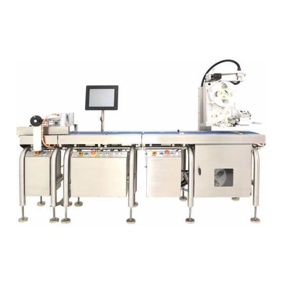
HI-700HS service manual - 1 - Installation Installation Contents- About the HI-700HS Shipment of machine Safety Moving the machine Rated operation conditions Programming note Installation requirements Installation - machine feet Fitting labeller to labeller arm Connections between weigh & labeller stations... - Page 9 HI-700HS service manual - 1 - Installation About this manual This service manual contains information for a qualified service engineer on aspects of the HI-700HS machine such as basic & detailed maintenance, component parts and recommended spare parts. HI-700HS The HI-700HS is a PC based high speed dynamic weigh labeller.
-
Page 10: Shipment Of Machine
Ensure when this port is not in use the protective cover is screwed on. Shipment of machine Machines leaving Digi Europe Ltd are normally shipped in a wooden crate, and the load cell clamped by the transit screws. These transit screws must be released before the machine is operated, see further in this section for details. -
Page 11: Safety
HI-700HS service manual - 1 - Installation Safety- your responsibilities In normal operation, it is essential that the scale cover, protective covers or panels are in place. The conveyors should be fitted and in their correct place for the machine to operate. - Page 12 Safety–Emergency stop The HI-700HS is fitted with an emergency stop switch on the main control box and the labeller power box When the machine is running, a sharp push on the button head will stop the conveyors.
-
Page 13: Moving The Machine
HI-700HS service manual - 1 - Installation Moving the machine When moving the machine the labeller should be supported to stop lateral movement. If moving only a short distance over a smooth surface the machine can be moved carefully to its new location with the aid of the lifting angles, supplied with the machine. -
Page 14: Programming Note
HI-700HS service manual - 1 - Installation Rated operational conditions for HI-700HS Climatic environment Temperature- lower limit = 0°C Upper limit = +30°C Humidity – non-condensing environment Intended location – closed (indoors) Mechanical environment The mechanical environment classes M1, M2 & M3 are not applicable to this automatic weighing machine (AWI). -
Page 15: Installation Requirements
HI-700HS service manual - 1 - Installation Installation requirements Site requirements This machine is designed to work within the normal environments associated with the food industry, i.e. humidity – non condensing environment and temperature between 0°C and +30°C. Weighing and labelling equipment is however sensitive to misuse and due care and attention should be given to the operating environment. -
Page 16: Installation Machine Feet
HI-700HS service manual - 1 - Installation Installation Machine feet Once the machine has had any packaging removed, place the machine in its required position. With the machine in position, lower the feet. Level the machine and ensure all feet are firmly on the solid ground. - Page 17 HI-700HS service manual - 1 - Installation Connections between weigh station & labeller station The HI-700HS uses a ‘plug & play’ method of connection between the two electrical cabinets If connecting a top labeller to the machine, the labeller conduit will have been disconnected for transit and therefore reconnec- tion is required.
- Page 18 HI-700HS service manual - 1 - Installation Labeller electrical cabinet connections Ethernet connection - connect the labeller Ethernet cable to the Ethernet switch. Connect to any of the four available ports Option - Outfeed Power lift connections 24v type -...
- Page 19 HI-700HS service manual - 1 - Installation Air pipe Feed the air pipe back out of the cabinet through cable gland and connect to the air regulator. Plug-in connections between labeller and weight station The two cables from the main electrical cabinet at the weigh station (marked IN & 1) are to be connected to...
-
Page 20: Hs Servo Indexer Connection
HI-700HS service manual - 1 - Installation HS servo indexer connection If the optional HI-HS servo indexer (standard for HI-HS-160) is to be used, connect this unit to the HI-HS main electrical cabinet using the multi pin connection on the side of the HI cabinet. -
Page 21: Outfeed Conveyor Connection
HI-700HS service manual - 1 - Installation Option fit part - Barcode scanner (Keyence) to end of outfeed If the optional fit Barcode scanner is installed, an additional electrical cabinet is fitted to house an I/O control board, DC- DC converter and electrical connection for scanner, trigger sensor and rejector. - Page 22 LA-3600 if the pack is deemed a reject (may be due to over / under weight / unstable etc). The wiring and software is pre-installed at factory build or can be retro-fitted using DIGI work instruction WI-357.1 OR WI-424.2.
-
Page 23: Outfeed Conveyor Connection
HI-700HS service manual - 1 - Installation Outfeed conveyor motor connection There is a round 8 pin connector for the outfeed conveyor motor which needs connecting to the 8 pin connector from the electrical box. The connector will be mounted on the rear side frame of the outfeed conveyor. Line up the connector pins in their correct position and fit connector together. -
Page 24: Removal Of Conveyor
HI-700HS service manual - 1 - Installation Removal of conveyor (to gain access to transit screw) The transit screws fitted to the scale for protection during transit needs to be released. Readjustment of the screws may be required to ensure a correct gap to act as limit stop screws in the up direction. - Page 25 HI-700HS service manual - 1 - Installation Transit screws After removal of the scale conveyor (see previous page), the transit screws can be adjusted to release the load cell from its transit setting The transit screws are at each end of the scale unit (circled left).
-
Page 26: Setting Corner Overload Stops
(approx. 1mm thick) as a gauge placed in the gap to obtain an even gap for all 4 stops. Tighten lock-nuts. For further details of setting the transit screws refer to DIGI Work instruction WI-442.1 1-19 Issue 2 06/2020... -
Page 27: Electrical Cabinet & Display Screen Operation Buttons
HI-700HS service manual - 1 - Installation Electrical cabinet & display screen operation buttons Electrical power on Emergency Start & stop Up / down power isolator indicator stop switch conveyors lift for labeller - switch see note below Switching on Once the electrical plug is plugged into a suitable power supply, turn the isolator switch 90°... -
Page 28: Labeller Position Adjustment
HI-700HS service manual - 1 - Installation Labeller position adjustment Ensure that the labeller is positioned such that packs can pass underneath it, with sufficient clearance for labels to be applied. Press the up / down power lift buttons on the front of the electrical cabinet to move the labeller height up or down, note: up / down buttons will be on the labeller electrical box for ‘plug &... -
Page 29: Loading Labels - Signature Top Labeller
HI-700HS service manual - 1 - Installation Loading labels - Signature top labeller Inside wound or outside wound labels can be used on the label- ler. The picture shows an outside wound label roll on the labeller on a left to right top labeller Important note: the label path should always run centrally through the labeller. - Page 30 HI-700HS service manual - 1 - Installation Feed labels over brake arm and Feed labels between label guide and through gap sensor, then pull smaller white roller (for outside through thermal head area. Tip - pull enough labels/paper through at...
- Page 31 HI-700HS service manual - 1 - Installation For inside wound label the label path uses the large web roller For inside wound labels, place the Return labels up and over the Feed labels around large web labels on the reel as above...
- Page 32 HI-700HS service manual - 1 - Installation Loading labels with Signature labeller fitted with centralizer option The label path for loading label is the same for the centralizer option as it is for the standard reel. The addition of the centralizer allow the labels to be easily centralized, therefore not needing to manually...
-
Page 33: Loading Labels - Classic Labeller
HI-700HS service manual - 1 - Installation Loading labels - Classic labeller To load the labels follow the route shown on the diagram and details below. Check labels are inside or outside wound and load accordingly Adjust rear spool position to allow centre of labels to run through the centre of the labeller Load labels onto spool. - Page 34 HI-700HS service manual - 1 - Installation Lift thermal head up from the platen roller Feed labels around the white guide roller, through the label gap sensor and between thermal head and platen roller Ensure backing paper is fed behind blow...
-
Page 35: Component Parts
HI-700HS service manual - 2 - component parts Component parts Contents- The weigh station electrical cabinet PC main board - type LV-67P Hard drive Battery Power supply LS75-15-15.8VDC UPS board 2-10 5 port Ethernet switch 2-11 Relay 5v 2-12 A/D power supply... -
Page 36: The Weigh Station Electrical Cabinet
The weigh station electrical cabinet The weigh station electrical cabinet for the HI-700HS machine has several outlets around the cabinet for various parts of the 700 machine to be connected into. The standard HI-HS machine uses a multi pin plug connection between electrical cabinet and labeller electrical cabinet. - Page 37 HI-700HS service manual - 2 - component parts The weigh station electrical cabinet Description Description MCB 10A (230V AC) A/D assembly Potentiometer (infeed speed control) A/D power supply HS indexer interface board (fitted if 24v PSU - RWS300B-24 HS indexing unit is connected Power supply LS75-15 15.8 VDC...
-
Page 38: Pc Main Board - Type Lv-67P
HI-700HS service manual - 2 - component parts PC main board - Type LV-67P Processor type - Intel® Pentium® N3710 - 1.6Ghz Memory - 4Gb DDR3 Hard drive Memory - SO-DIMM1 connection Launch button connection PC processor COM 5 & 6 DC in COM 3 &... - Page 39 HI-700HS service manual - 2 - component parts PC main board - Type LV-67P - COM 3 & 4 A cable form plugged into the main board (COM 3 & COM 4) is attached to two DB9 connectors which are mounted beside the Ethernet switch...
- Page 40 HI-700HS service manual - 2 - component parts PC main board - Type LV-67P - COM port 2 configuration JCSEL1, JCSEL2 : For configure COM2 communication mode Function JCSEL1 JCSEL2 RS232 RS485 RS422 JCSEL1 JCSEL2 Issue 1 02/2020...
-
Page 41: Hard Drive
HI-700HS service manual - 2 - component parts Hard drive The standard single hard drive used is a solid state type, typically 60Gb in size with Sata type connection. The hard drive holds the Windows® embedded standard image, the console or Worldview operation software and programmed data such as plu’s, label formats etc. -
Page 42: Battery
HI-700HS service manual - 2 - component parts Battery The battery is a 12v 1.2AH maintenance free sealed lead acid type. A charge is provided to it from the 15.8v power supply via the UPS board. (charge voltage approx. 15v for Pico UPS-100) The battery is used if a sudden power failure occurs. -
Page 43: Power Supply Ls75-15-15.8Vdc
HI-700HS service manual - 2 - component parts Power supply 15.8v (LS75-15) This power supply supplies 15.8 volts to the UPS board which in turn transfers this voltage to the PC main board(15.8v) The input voltage (240v AC) is supplied from the terminal rail connection 15.8v power supply location... - Page 44 HI-700HS service manual - 2 - component parts UPS board - Pico UPS-100 The UPS board controls the circuit for the un-interruptible power supply (UPS) . The board has a 15.8v input from the power supply LS75-15 and outputs 15.8v to the PC.
-
Page 45: Port Ethernet Switch
HI-700HS service manual - 2 - component parts 5 port Ethernet switch The 5 port Ethernet switch is the connection point for all labeller / printer that are to be connected to the machine The switch is supplied a voltage of 5v from the PC main board... -
Page 46: Relay 5V
HI-700HS service manual - 2 - component parts Relays 5v There are two relays (both the same type) in the cabinet Relay 1 - acts as the ‘switch’ for the backup voltage (battery) to take over if the normal power fails. -
Page 47: A/D Power Supply
HI-700HS service manual - 2 - component parts A/D power supply The A/D power supply supplies DC voltage of 9v and 5v to the A/D unit. Connection of 5v and 9v to A/D Along the top of the board is four LED’s. -
Page 48: A/D Unit
HI-700HS service manual - 2 - component parts A/D unit The analogue to digital (A/D) unit is the device for converting the analogue values from the load cell (actual strain gauge bridge voltage) to a digital signal and transmitting these values (via RS232 serial) to the main board. - Page 49 HI-700HS service manual - 2 - component parts A/D power supply connection Serial connector (9way D type) connects to main board at COM port 2 Connection to pack sensor circuit from PLC A/D Security switch To serial connection on main board...
- Page 50 HI-700HS service manual - 2 - component parts Power supply 24v - RWS300B-24 This 24v PSU supplies 24v to the contactor, motor drivers and conveyor stop – start circuit. Refer to electrical drawing for exact route of connections. • The RWS300B-24 has an output DC of 24v / 12.5A...
-
Page 51: Omron Plc
HI-700HS service manual - 2 - component parts Omron PLC The PLC unit consists of 3 units, the power unit (PA201), the PLC unit (CPM2C 20CDTC-D) and the analogue I/O unit (MAD11). The PLC deals with input and output signals to and from various parts of the machine. E.G – pack sensors, conveyor speed, reject signal. - Page 52 HI-700HS service manual - 2 - component parts PLC unit CPM2C Refer to the electrical drawings for more details on the connection to and from this unit. Serial connection to pc main board Red=24v term rail To speed control Yellow=start button...
- Page 53 HI-700HS service manual - 2 - component parts MAD11 analogue unit Refer to the electrical drawings for more details on the connection to and from this unit. To Motor speed control boards Black to VRM (v-) Orange to VRL (v+)
-
Page 54: Motor Driver Board
HI-700HS service manual - 2 - component parts Motor driver board Each conveyor is powered by a brushless DC motor fitted with gearhead, controlled by a AXHD50K motor driver. The driver is illustrated below. There is a motor driver board for each conveyor fitted to the machine. In the main electrical cabinet the infeed and scale motor drivers are fitted. - Page 55 HI-700HS service manual - 2 - component parts Motor driver board Black Black Blue Purple 2-21 Issue 1 02/2020...
- Page 56 HI-700HS service manual - 2 - component parts Conveyor speed setting - initial factory default setup The potentiometers in the main electrical cabinet and the labeller electrical cabinet are connected to each of their respective motor driver board. The main electrical cabinet will have the infeed & scale, the labeller electrical cabinet will have the outfeeds.
-
Page 57: Miniature Circuit Breaker
HI-700HS service manual - 2 - component parts Miniature circuit breaker (2 pole / 4A) Inside the electrical cabinet there is a miniature circuit breaker (MCB) at the incoming electrical supply Circuit breaker in OFF position. The indicator window will show green Circuit breaker in ON position. -
Page 58: Software Licence Dongles
HI-700HS service manual - 2 - component parts Software licence dongle The dongle is the licence key to allow the operation of the Console or Worldview software. The dongle is plugged into one of the USB ports on the PC main board and must remain in place to obtain correct operation of the machine. -
Page 59: I/O Board For Hs Indexing Unit
HI-700HS service manual - 2 - component parts I/O board for HS indexing unit The I/O board for HS indexing unit is fitted when the machine has the HS Servo motor driven infeed unit. This unit may be a single Servo drive (conveyor only) or conveyor and side drives (3 servo unit). - Page 60 HI-700HS service manual - 2 - component parts Pack sensor - Optoelectronic retro reflective type sensor. (Wenglor KR87NCT2) This sensor is mounted across or overhead the infeed and scale conveyors. The sensors are supplied 24v from the 24v terminal rail inside the control box...
-
Page 61: Conveyors (Hs Type)
HI-700HS service manual - 2 - component parts Conveyors (HS type) Conveyor removal from machine Each conveyor is held in place with four clips mounted at the sides of the conveyor. Release these clips to allow removal of the conveyor deck from the machine. - Page 62 HI-700HS service manual - 2 - component parts Conveyors (HS type) - identification of parts The conveyor shown below is a typical HS conveyor (non scale). The length and width varies depending on machine specification. Reflector in deck for overhead pack sensor, where required.
- Page 63 HI-700HS service manual - 2 - component parts Conveyors - scale (HS type) - identification of parts The scale conveyor is a similar construction to the standard HS conveyor with the addition of: • Cable motor clip • Conveyor belt guide •...
- Page 64 HI-700HS service manual - 2 - component parts Outfeed conveyor when base labeller is fitted The BL outfeed conveyor is one complete assembly incorporating two sets of conveyors. It is removed from the machine in the same way as other HS type conveyors...
-
Page 65: Hs Servo Infeed Assembly
HI-700HS service manual - 2 - component parts HS servo infeed assembly If fitted, the HS Servo infeed assembly will be at the start of the HI-700HS. The assembly may be constructed with a single Servo driven conveyor or with the addition of servo driven side guides. - Page 66 HI-700HS service manual - 2 - component parts Removal of conveyor in HS servo infeed assembly Open guides fully wide for both standard and powered guides, (see previous page for adjustment detail). Unclip the four conveyor retaining clips Lift conveyor to access the servo motor...
- Page 67 HI-700HS service manual - 2 - component parts HS servo infeed assembly - electrical cabinet The electrical cabinet for the HS infeed assembly contains the control units for each servo motor Front view Rear view Isolator switch Power indicator lamp...
- Page 68 HI-700HS service manual - 2 - component parts HS servo infeed assembly - electrical cabinet Single servo unit Triple servo unit (powered side guides) Identifying the parts inside the electrical cabinets The Servo infeed electrical cabinets contains the items required to drive the single or triple servo units Both units have similar parts with the triple unit requiring a Ethernet switch &...
-
Page 69: Labeller Electrical Control Cabinet
HI-700HS service manual - 2 - component parts Labeller (Outfeed) electrical control cabinet The HI-HS with a multi pin plug type connections has an additional electrical cabinet under the outfeed conveyor which houses various components related to the labelling station. - Page 70 HI-700HS service manual - 2 - component parts Labeller (Outfeed) electrical control cabinet Description 24v power supply - power to motor driver boards 5v power supply - power to Ethernet switch Ethernet switch - labeller connection Motor driver board - control to conveyor motors...
-
Page 71: Load Cell
HI-700HS service manual - 2 - component parts Load cell The load cell fitted to the scale unit can be either a 15kg or 30kg depending on the specification required for the scale. NOTE: these capacities are not the machine/scales capacity. Typically this will be a machine capacity of 6kg for the 15kg load cell and a machine capacity of 12kg for the 30kg load cell. - Page 72 HI-700HS service manual - 2 - component parts Load cell specification & connecting plug wiring The load cell is a single point type of double bending beam transducer construction • Material: stainless steel • Protection class: IP67 • Sensitivity (Cn): 2.0 +/- 0.2 mV/V •...
-
Page 73: Touch Screen 12.1
HI-700HS service manual - 2 - component parts Touch screen - 12.1’’ The colour touch screen on the 700 series machine with LV-67P main board is made up of: • 12.1 LED TFT screen • Touch panel – 12.1 Fujitsu touch panel •... - Page 74 HI-700HS service manual - 2 - component parts Screen parts Seal With the LED screen removed, the touch panel can be seen. Note the seal on front side of touch panel Touch panel The touch panel is the front glass panel in front of the LED screen.
- Page 75 HI-700HS service manual - 2 - component parts Electronic board - assy USB touch PCB This PCB links the touch panel to the PC main board. The input & output signals to & from the touch screen are processed though this board and onto the PC main board.
-
Page 76: Touch Screen 15
HI-700HS service manual - 2 - component parts Touch screen - 15’’ HS LED - PC on indicator Launch button for starting PC is on the underside of the screen enclosure USB port mounted on the side of the enclosure... -
Page 77: Labeller - Signature
HI-700HS service manual - 2 - component parts Labeller - Signature The standard top labeller fitted to the HI-HS is shown below. This is known as the Signature high speed labeller. This labeller is handed therefore is build left to right or right to left depending on machine flow direction For top labelling the applicator can be touch (9 fingers), multi jet air box or HS blow. - Page 78 HI-700HS service manual - 2 - component parts Labeller - Classic The Classic type labeller is an option fit instead of using the Signature labeller. The example below has the 9 finger touch applicator fitted. Common parts exist between the Signature &...
-
Page 79: Thermal Head
HI-700HS service manual - 2 - component parts Thermal head Thermal head fitted to labeller is either: KD3003-DC72B – 80mm wide with dot pitch of 11.8 dots per mm (standard fitment) KF3004-GM50D – 108mm wide with dot pitch of 11.8 dots per mm The head has a history control and driver LSI which has the function of thermal historical control of the temperature / power required for each head dot. -
Page 80: Wear Strip & Silicone Tube (Signature)
HI-700HS service manual - 2 - component parts Wear strip & silicone tube - for Signature labeller The wear strip & silicone tube act as a pressure pad against the underside of the label which will then press the label onto the thermal head. - Page 81 HI-700HS service manual - 2 - component parts Platen roller option - Signature labeller A platen roller option can be fitted to the Signature labeller instead of using the wear strip (near edge) assembly If near edge printing is not required or the labeller is to used with thermal ribbon the platen roller kit option can be fitted.
- Page 82 HI-700HS service manual - 2 - component parts Thermal head heaters - Signature labeller On the Signature labeller thermal head heaters are fitted into the head assembly as standard. There are two heaters which are connected to the 25v power supply via two Molex connectors in the rear...
-
Page 83: Labeller Board
HI-700HS service manual - 2 - component parts Labeller board J5 – label gap sen- For software For software Labeller IP sor value Label feed programming programming address setting. adjust – button and - also see (print side) - Take up motor Gap sensor. - Page 84 HI-700HS service manual - 2 - component parts Labeller sensor I/F board - Signature labeller On the labeller board of a Signature labeller there is a sensor interface board mounted. The label gap sensor is connected to this board and its sensitivity can be adjusted via this board...
-
Page 85: Labeller Sensor I/F Board
HI-700HS service manual - 2 - component parts Power supply 5.35v (TXL 015-05S) This PSU supplies 5.35v for the control circuit of the labeller board 5.35v power supply Note: this image shows the power supply in the Signature labeller NOTE: The standard manufactures output voltage for this power supply is 5V. -
Page 86: Power Supply 25V
HI-700HS service manual - 2 - component parts Power supply 25v (LS200-24) This PSU supplies 25v onto the labeller board which will then supply: The thermal head The cooling fan (for stepper motor) Solenoid valve operation 25v PSU Backing paper take-up motor... -
Page 87: Power Supply 42V
HI-700HS service manual - 2 - component parts Power supply 42v (LS200-48) This PSU supplies 42v to the stepper motor. The input voltage to this power supply is 100-240vAC and this voltage is obtained from the labeller mains terminal connection inside the main electrical cabinet. -
Page 88: Stepper Motor
HI-700HS service manual - 2 - component parts Stepper motor The stepper motor is the motor used to pull the label through the labeller, feeding it the correct distance required for the given label length. It rotates the drive roller on the labeller via a tooth belt The stepper is connected to the labeller board onto PL9 and is powered by the 42v PSU. -
Page 89: Take-Up Motor
HI-700HS service manual - 2 - component parts Take-up motor The take-up motor is used to turn the backing paper take-up spool to wind the label rolls backing paper on- to the spool. The motor drives the spool via a toothed belt and pulleys. -
Page 90: Label Gap Sensor
HI-700HS service manual - 2 - component parts Label Gap sensor Signature labeller type shown The label gap sensor detects the label and the gap between labels to obtain the correct label feed out length. Both the sensor parts are mounted into an upper & lower bracket with a fixed position mounted behind the thermal head. -
Page 91: Power On/Off Switch
HI-700HS service manual - 2 - component parts Power ON/OFF switch To isolate the labeller from main power (230v), use the toggle switch in the rear of the labeller. This is mounted at the top of the 42v power supply... - Page 92 HI-700HS service manual - 2 - component parts Touch applicator - Signature labeller The touch applicator has 9 independently sprung fingers that are that are driven down & up via a pneumatic air cylinder Inside the applicator unit there are two 24v fans to create an up flow of air to hold the label on the applicator...
-
Page 93: Blow Bar
HI-700HS service manual - 2 - component parts Blow bar The blow bar mounted on the labeller under the stripping bar assembly is used to blow jets of air up towards the applicator shoe when the label is being fed out. This flow of air aids the label onto the shoe It is important to ensure the holes in the blow bar point at the correct angle to ensure correct direction or air flow from the holes to guide the label onto the applicator shoe. -
Page 94: Pneumatic Connections
HI-700HS service manual - 2 - component parts Pneumatic connections The following is a diagram of the air valve connections within the touch applicator assembly. The solenoid valves electrically connect to the labeller board at PL6 & PL7 700 LABELLER BOARD. - Page 95 HI-700HS service manual - 2 - component parts Multi jet air box applicator The top labeller air box applicator has a slot in the side which allows the fitting of a blanking plate to cover certain areas of the air jets. This is to concentrate the air flow in a set area for different size labels.
-
Page 96: Hs Blow Applicator
HI-700HS service manual - 2 - component parts HS blow applicator The HS blow applicator is a high speed blow type application Refer to section 4 serving for set- up instruction for this applicator (or refer to work instruction WI-449.1) - Page 97 HI-700HS service manual - 2 - component parts HS blow applicator Air jet restriction Move the sliding blanking plates to increase or decrease the amount of holes on the underside of the label receiver that will allow air out to blow the label down to the pack.
- Page 98 HI-700HS service manual - 2 - component parts HS blow applicator - Pneumatics 2-64 Issue 1 02/2020...
-
Page 99: Base Labeller Belt Applicator
HI-700HS service manual - 2 - component parts Base labeller belt applicator The base labeller has a belt type applicator which feeds the labels up from the thermal head along four belts and onto the base of the pack. The belts run at a fixed speed and are controlled by their own dc motor and motor driver unit NOTE: the motor driver units in this labeller electrical cabinet look very similar but have a different power output. -
Page 100: Touch Applicator - Classic Labeller
HI-700HS service manual - 2 - component parts Touch applicator (9 finger) - Classic labeller The standard applicator on the classic labeller is the 9 finger touch. This applicator has 9 individually sprung fingers which are moved up and down by a double acting air cylinder. - Page 101 HI-700HS service manual - 2 - component parts Pneumatic control - Classic labeller touch applicator The following is a diagram of the air valve connections within the touch applicator assembly. 5/2 VALVE - SY3120 5/2 VALVE SY3120 The solenoid valves electrically connect to the labeller board at PL6 & PL7 700 LABELLER BOARD.
-
Page 102: Routine Maintenance
HI-700HS service manual - 3 – routine maintenance Routine Maintenance Contents- Removal and cleaning of conveyor belts Pack sensors Cleaning the thermal head Cleaning labeller drive and pressure rollers Condition of wear strip / platen roller (Signature labeller) 3-7 Condition of platen roller (classic labeller) - Page 103 HI-700HS service manual - 3 – routine maintenance Routine maintenance It is essential that general maintenance and cleaning is carried out on a regular basis to ensure the machine is kept in full working order. WARNING Ensure that the machine is switched off and disconnected from the electricity and air supplies before starting any maintenance.
-
Page 104: Pack Sensors
HI-700HS service manual - 3 – routine maintenance Pack sensors The pack sensors need to be kept clean to ensure correct operation of the 700 series machine. The sensors may be mounted overhead or across the deck of the conveyor, one at the infeed conveyor &... - Page 105 Once the machine is power off (including isolator), open the thermal head assembly as shown above. Place a clean 'Safesleeve' (Digi part no. MM9-00034) on the blue 'Safewand' (Digi part no. MM9-0033) and moisten with an approved cleaning fluid. It is recommended that Isopropyl alcohol be used.
- Page 106 HI-700HS service manual - 3 – routine maintenance Cleaning the thermal head - Signature & Classic labellers BE CAREFUL Do not use any sharp implements to remove label debris from the thermal head surface. Safesleeve Safewand Apply light pressure upwards along the thermal head and thoroughly clean the surface. Ensure all deposits are removed.
- Page 107 HI-700HS service manual - 3 – routine maintenance Labeller drive / pressure roller cleaning To ensure the drive & pressure rollers grip the backing paper for correct drive of labels, the pair of rollers should be cleaned regularly. BE CAREFUL - The drive roller material can be sensitive to some cleaning agents.
-
Page 108: Condition Of Platen Roller (Classic Labeller)
HI-700HS service manual - 3 – routine maintenance Condition of wear strip - Signature labeller The print head wear strip needs to be in good condition, with no debris on it to ensure a good print quality. Lift the print head by turning the black Check wear strip is clean and in good condition. -
Page 109: Cleaning The Control Box And Display
HI-700HS service manual - 3 – routine maintenance Cleaning control box and display Switch off and disconnect the machine from the mains electricity supply. Wipe the control boxes and display using a soft lint free cloth moistened with warm, dilute detergent. -
Page 110: Servicing
HI-700HS service manual - 4 – servicing Servicing Contents- Conveyors HS type conveyor Conveyor belt replacement Conveyor strip down for roller, drive belt & tensioner replacement Conveyor re-assembly - motor pulley grub screw location 4-10 Re-assembly of conveyor 4-11 Setting drive roller height to deck... - Page 111 HI-700HS service manual - 4 – servicing Contents continued - Labeller electronic board (Signature & Classic) 4-72 Take-up motor torque setting 4-74 Brake arm - position & adjustment 4-75 Brake arm - setup for inside wound labels 4-77 Updating labeller board software 4-80 Air flow adjustment &...
- Page 112 HI-700HS service manual - 4 – servicing Conveyor - HS type The HS type conveyor uses four clip, one at each corner, to secure it in place on the frame assembly (or scale deck if scale conveyor). Refer to section 1 - installation or section 2 - component parts for details on how to remove the conveyor from the machine.
-
Page 113: Conveyor Belt Replacement
HI-700HS service manual - 4 – servicing Conveyor belt replacement The conveyor belts can be replaced by first releasing the tension created by the adjustments at the idler roller Using a ball end hex key, place in slot in the side of the conveyor at the idler roller end. - Page 114 HI-700HS service manual - 4 – servicing Conveyor belt replacement - continued With the conveyor belts removed from the deck, the idler roller can easily slide out of its location, therefore care should be taken not to let this fall out...
-
Page 115: Conveyor Strip Down For Roller, Drive Belt & Tensioner Replacement
HI-700HS service manual - 4 – servicing Conveyor strip down for roller, drive belt & tensioner replacement This process is for standard HS type conveyors & scale conveyors. For servo infeed conveyor and base labeller conveyor see further sections With the conveyor belts removed, see previous two pages for this process, the conveyor can be taken apart to replace required items. - Page 116 HI-700HS service manual - 4 – servicing Conveyor strip down for roller, drive belt & tensioner replacement - continue Unscrew and remove the two end bolts & washers The motor can move down now to release holding the drive belt in place...
- Page 117 HI-700HS service manual - 4 – servicing Conveyor strip down for roller, drive belt & tensioner replacement - continue Loosen the two captive screws holding the belt cover Remove belt cover Remove the four screws and washers holding The toothed drive belt can now be removed.
- Page 118 HI-700HS service manual - 4 – servicing Conveyor strip down for roller, drive belt & tensioner replacement - continue The guide pulley or guide roller can be replaced as complete assembly. This is advisable as each part is glued / pressed together to make If the guide pulley or guide roller need to be the assembly.
- Page 119 HI-700HS service manual - 4 – servicing Re-assembly - motor pulley grub screw location Important - the fitting of the motor pulley is slightly different depending if the assembly is for a standard conveyor or a scale conveyor Scale motor assembly The scale motor assembly (shown left) must have a grub screw in all four positions in the pulley.
- Page 120 HI-700HS service manual - 4 – servicing Re-assembly of conveyor - continued See note below Fit motor / gearhead assembly to motor Fit the four screw with washers to hold the motor bracket. Ensure toothed drive belt is assembly in place.
-
Page 121: Setting Drive Roller Height To Deck
HI-700HS service manual - 4 – servicing Re-assembly of conveyor - continued - setting drive roller height to deck When the drive roller bracket (s) have been removed to allow removal of the drive roller, these brackets must be set back in the correct place to ensure the height of the roller in relation to the deck is correct. -
Page 122: Setting Idler Roller Height To Deck
HI-700HS service manual - 4 – servicing Re-assembly of conveyor - continued - setting idler roller height to deck If the idler roller plates have been loosened / Idler roller plate removed they must be reset to the correct height to ensure the... -
Page 123: Low Friction Tape
HI-700HS service manual - 4 – servicing Low-friction tape The conveyor deck has strips of UHMWpe tape. This tape should be periodically checked to ensure it is in good condition. If it is found to be worn or damaged the strip or strips should be replaced. -
Page 124: Servo Infeed Deck (500Mm)
HI-700HS service manual - 4 – servicing Servo infeed deck (500mm) The Servo infeed deck construction is similar to other standard conveyor decks with the exception of having a Servo motor instead of the usual DC motor and gearhead assembly... -
Page 125: Outfeed Conveyor For Base Labeller
HI-700HS service manual - 4 – servicing Outfeed conveyor for base labeller The construction of the outfeed conveyor for base labelling is different to other conveyors. The single DC motor / gearhead assembly drives both the long and short sets of conveyor belts with a toothed drive belt system linking the two conveyors. - Page 126 HI-700HS service manual - 4 – servicing Outfeed conveyor for base labeller - conveyor belt removal continued Unscrew the six cap head screws in the side of the joining bar, remove the joining bar. Lift out the idler roller bar from the bush Slide the short and long conveyor belts off of the conveyor assembly Note: the idler rollers sit in the idler roller plates at the end of each conveyor.
-
Page 127: Outfeed Conveyor For Base Labeller - Idler Roller Removal
HI-700HS service manual - 4 – servicing Outfeed conveyor for base labeller - idler roller removal One or both Idler rollers can now be removed. Inspect condition of roller assembly, check for smooth rotation, replace if required Idler roller assembly - 718-0009 (x2) - Page 128 HI-700HS service manual - 4 – servicing Drive assembly - continued Loosen the four fixings securing the motor assembly. Important note: one fixing (bottom right in photo left) is in the assembly the opposite way round to the other three (head...
- Page 129 HI-700HS service manual - 4 – servicing Drive assembly - continued Loosen and remove the fixing for the belt tensioner post. Inspect condition and check it rotates freely. If replacing any of the tensioner parts, when reassembling the tensioner, use Loctite 641...
- Page 130 HI-700HS service manual - 4 – servicing Drive assembly - continued Loosen the grub screws in the other Slide the two pulleys and toothed belt off the roller two pulleys shafts together. Inspect all parts and replace any worn or damaged parts.
- Page 131 HI-700HS service manual - 4 – servicing Removal of drive rollers Keeping the bearing block upright, tap the roller shaft on the motor side the release the roller from the conveyor assembly. On assembly, Loctite is use on these rollers to secure in place.
- Page 132 HI-700HS service manual - 4 – servicing Re-assembly - Important points to note Belt tensioner post assembly Use Loctite 641 between belt tensioner post & bearings and also between idler sleeve & bearings. Press bearings into sleeve and post into bearings.
- Page 133 HI-700HS service manual - 4 – servicing Low friction tape fitment to decks 710-0088 710-0089 Tape, 25mm UHMWpe—cut 720mm - MM8-00030 (c) Tape, 25mm UHMWpe—cut 262mm - MM8-00030 (d) Cut four strips of MM8-00030 (c) and stick to deck 710-0088 in positions show below...
- Page 134 HI-700HS service manual - 4 – servicing Fitting catch plates Use M4x12 pozi screws (x2) to secure catch plate to conveyor deck. Use Loctite 243 on screw threads Bearing blocks & joining plate assemblies If fitting new bearings into the bearing blocks or joining plate use Loctite 641 between bearing and block / plate.
- Page 135 HI-700HS service manual - 4 – servicing Fit drive roller assembly to long and short decks Ensure the roller is pushed fully in against the inner race of the bearing. Use Loctite 641 between shaft and bearing When fitting bearing block to roller shaft use...
-
Page 136: Load Cell
HI-700HS service manual - 4 – servicing Weighing - load cell If the load cell requires replacing, the machine will require a re-calibration. To aid easy replacement the load cell is supplied with a cable gland and cover plate fitted to the load cell cable. This allows the routing of the cable through the machine without the need to remove the plug which connects to the ADC. - Page 137 HI-700HS service manual - 4 – servicing Load cell removal - scale top frame removal Unscrew and remove one of the transit / over- load stop screws. Loosen the two side screws Unscrew and remove the two top screws The top scale frame can now be lifted...
-
Page 138: Load Cell Removal
HI-700HS service manual - 4 – servicing Load cell removal - continued Loosen the two side screws Unscrew and remove the two screws located on the underside of the scale base bar The load cell can be lifted from the scale base assembly. -
Page 139: Re-Assembly
HI-700HS service manual - 4 – servicing Re-assembly Re-fitting the load cell back into the scale assembly is the reversal of the dis-assembly process but also noting the following important assembly points Place loadcell into groove of mounting block. Ensure correct orientation of... - Page 140 HI-700HS service manual - 4 – servicing Re-assembly - continued These screws to be Place scale top assembly onto tightened to torque load cell. value of 14Nm Use the two side screws in the into loadcell scale top bar to lightly tension loadcell to opposite side.
- Page 141 HI-700HS service manual - 4 – servicing Re-assembly - continued Latch block & deck levelling pin If this assembly has been dis-assembled, fit grub screw loose at initial re-assembly stage, allowing latch block to rotate freely on pin tighten grub screw into pin groove after fitting...
- Page 142 HI-700HS service manual - 4 – servicing Re-calibration of scale - using Worldview software (dynamic weighing type) IMPORTANT: This operation to be undertaken by the distributor or other qualified persons using traceable calibrated weights Calibration Go to service menu / scale settings -...
- Page 143 HI-700HS service manual - 4 – servicing Zero option This re-zero function can be used if the scale has drifted too far from its zero point and therefore not allowing the operation screen re-zero to work. Note: No weights are required for this process but as with calibration, ensure scale area is clear of any debris.
- Page 144 HI-700HS service manual - 4 – servicing Re-calibration of scale - using Console software (dynamic weighing type) IMPORTANT: This operation to be undertaken by the distributor or other qualified persons using traceable calibrated weights. Before starting the calibration, ensure the scale capacity options are set correctly To enter the scale menu the ADC security switch needs to be set.
- Page 145 HI-700HS service manual - 4 – servicing Calibrate zero & span Use this function to calibrate the scale. Note: before starting this process, ensure the span weight value is known and suitable calibrated weights are available. Ensure the scale capacity options are set correctly To calibrate the machine, touch the calibrate zero &...
-
Page 146: Electrical Cabinet A/D Unit
HI-700HS service manual - 4 – servicing Electrical cabinet - ADC unit If an ADC unit is needed to be replaced, any metrological data (i.e. – capacity details, calibration, and sub-span data) will all need to be re-entered, (also see following page showing where data is stored). - Page 147 HI-700HS service manual - 4 – servicing Data storage on ADC board The metrological data (i.e. – capacity details, calibration, and sub-span data) is stored on the IC marked IC19 ADC security switch location No.1 switch Set Security switch No. 1 to the OFF position to allow entry to scale settings.
-
Page 148: Checksum Mismatch Error
HI-700HS service manual - 4 – servicing Checksum mismatch error This error can be due to the new weighing part (ADC) being fitted and/or change of software installed. The checksum which is created by the machine will still match the original part/software therefore a new checksum needs to be established. - Page 149 HI-700HS service manual - 4 – servicing Checksum mismatch error - continued To overcome this error with Worldview software go to: Service menu / Scale settings / ADC settings (set ADC security switch to OFF to allow entry - see page 4-38 for location)
-
Page 150: Hard Drive Replacement
HI-700HS service manual - 4 – servicing Hard drive replacement - (Sata connection to LV-67P main board) The hard drive is mounted at the lower right side inside the electrical cabinet. The following describes the removal / replacement of the hard drive. - Page 151 HI-700HS service manual - 4 – servicing The hard drive is now free to remove from the machine. The mounting bracket can be reused on the replacement hard drive unit. To remove bracket, loosen the four screws at the side of drive and lift drive from bracket.
-
Page 152: Pack Sensor Adjustment - Opto Electric (Wenglor)
HI-700HS service manual - 4 – servicing Pack sensor adjustment - opto electric (Wenglor) In electrical cabinet, each pack sensor cable connects to a 3 way Molex connector. Linked to this connector is another Molex connector with a single wire connection. This wire is the Teach wire. -
Page 153: Led Screen & Touch Panel - 12.1
HI-700HS service manual - 4 – servicing LED screen & touch panel - 12.1’’ version If the touch panel or LED screen becomes damages or fails to work correctly, follow the procedure below to gain access to the screen assembly. - Page 154 HI-700HS service manual - 4 – servicing To remove the LED screen, unscrew the 8 screws around the edge of the rear metal frame. Before lifting the LED assembly, unplug the touch panel ribbon cable from the USB / touch PCB...
- Page 155 HI-700HS service manual - 4 – servicing The touch screen can now be removed from the outer screen surround. If the touch panel is to be replaced, be careful to keep the glass surface clean from dirt / fingerprints on the inner face.
- Page 156 HI-700HS service manual - 4 – servicing When refitting touch panel, ensure the ribbon cable fits correctly into the surround cut-out. Reassemble with the insulated support and the inner frame. Ensure the 12 plastic screws are replaced. Do not use metal screws in this part of the assembly.
- Page 157 HI-700HS service manual - 4 – servicing Calibration of touch panel - 12.1'' version If the touch points on the screen are not matching with where you are touching the screen, the screen may need to be calibrated. With the machine switched on, exit to Windows®...
- Page 158 HI-700HS service manual - 4 – servicing LED touch screen assembly - 15’’ version If the LED touch screen assembly becomes damages or fails to work correctly, follow the procedure below to gain access to the assembly. Before starting the disassembly, ensure the machine is shut down and the power turned off.
- Page 159 HI-700HS service manual - 4 – servicing Remove screen assembly from outer fascia To remove the screen assembly from the fascia, unscrew the 16 screws around the edge of the rear metal frame The screen assembly can be lifted clear of the...
- Page 160 HI-700HS service manual - 4 – servicing Screen assembly The screen assembly is a one piece unit consisting of the LED screen and touch panel combined. The touch panel interface board is also part of the same assembly when required as a spare part...
- Page 161 HI-700HS service manual - 4 – servicing Calibration of touch screen - 15'' version If the touch points on the screen are not matching with where you are touching the screen, the screen may need to be calibrated. With the machine switched on, exit to Windows® level On the desk top, click on the icon ‘eGalaxTouch’...
- Page 162 HI-700HS service manual - 4 – servicing 15’’ HS style screen The 15’’ HS style screen assembly can be opened at the rear to access the component parts of the assembly At the rear of the screen assembly use the cam latch key to turn the two cam locks 1/4 turn to open and release the rear cover.
- Page 163 HI-700HS service manual - 4 – servicing 15’’ HS style screen Description Part no. Display NLB150XG02L-01 765-001 Mtg bracket for display 710-0281 Assy USB touch screen PCB B569-185 Assy 15’’ touch screen + gasket 718-0055 Locator 15’’ touch screen 710-0279 Clamp 15’’...
- Page 164 HI-700HS service manual - 4 – servicing Signature labeller servicing Thermal head 80mm 565-743 Thermal head 108mm EX0-00030 Silicone tube - 701-0047 Wear strip - 701-0048 Platen roller - 701-0051 (option fit) Thermal head pneumatic pressure Standard values are: Signature labeller Torque wrench settings - Nm 80mm wide thermal head = 0.25 to 0.3 MPa...
-
Page 165: Removal Of Thermal Head
HI-700HS service manual - 4 – servicing Signature labeller Removal of thermal head If the thermal head is to be disconnected and removed, the electrical power to the labeller must be turned off. Open the applicator latch and hinge the applicator away from the print head area. - Page 166 HI-700HS service manual - 4 – servicing Signature labeller - thermal head replacement continued Un-screw the carrier plate from the thermal head (3 cross-head screws) Replace the carrier plate onto the new thermal head. Note the location pins in the carrier plate that locate into the holes in the thermal head.
-
Page 167: Replacement Of Wear Strip
HI-700HS service manual - 4 – servicing Signature labeller - Replacement of wear strip When the wear strip has worn out or become damaged, the quality of print will deteriorate. The wear strip is held in-place by the near edge stripping bar clamping it between that and the near edge... - Page 168 HI-700HS service manual - 4 – servicing Stripping bar with wear strip and silicone tube The wear strip can be lifted off the rear pins on the stripping bar and replaced with a new one Check the condition of the silicone tube and replace if required.
- Page 169 HI-700HS service manual - 4 – servicing Signature labeller - platen roller replacement If the platen roller becomes damaged whereby the surface is not smooth and even or worn causing indentation the print quality will deteriorate. To replace the platen roller,...
-
Page 170: Thermal Head Pressure
HI-700HS service manual - 4 – servicing Signature labeller - thermal head pressure The pressure exerted by the air cylinder above the head assembly pushes the thermal head onto the label, wear strip and silicone tube. This pressure can affect the quality of the print on the label. -
Page 171: Thermal Head Horizontal Position
HI-700HS service manual - 4 – servicing Signature labeller - thermal head horizontal position Head set up position - wear strip type & platen roller The head mounting plate (701-0021) which is fixed to the labeller back plate with four hex head screws... - Page 172 HI-700HS service manual - 4 – servicing Signature labeller - thermal head horizontal position Head set up position - wear strip With the thermal head position set to its default position (see previous page) the head set up position can be set Loosen the four hex head screws holding the mounting plate to the back plate.
- Page 173 HI-700HS service manual - 4 – servicing Signature labeller - thermal head horizontal position Head set up position - platen roller type If the labeller has the platen roller fitted (instead of near edge assembly) the default mounting plate position is different...
- Page 174 HI-700HS service manual - 4 – servicing Signature labeller - thermal head horizontal position Head set up position - continued When moving the mounting plate back / forward the position of the thermal head to the stripping bar is set.
- Page 175 HI-700HS service manual - 4 – servicing Signature labeller - thermal head horizontal position Fine adjustment using adjuster screws If the head mounting plate had been moved or the print is poor, the two adjuster screws can be adjusted for a fine adjustment of the horizontal thermal head position.
-
Page 176: Thermal Head Vertical Position
HI-700HS service manual - 4 – servicing Signature labeller - thermal head vertical position When the air pressure is off the thermal head should be in a certain position when locked down with a set gap between the thermal head print face and the wear strip or platen roller. -
Page 177: Air Cylinder Position On Head Assembly
HI-700HS service manual - 4 – servicing Signature labeller - air cylinder position on head assembly With the thermal head in its locked down position there should be a small gap (approx. 1mm) between the cylinder rod end cap and the head adjustment block Small gap (approx. -
Page 178: Label Gap Sensor Sensitivity Adjustment
HI-700HS service manual - 4 – servicing Signature labeller - label gap sensor sensitivity adjustment The label gap sensor, mounted behind the thermal head area can be adjusted for correct label detection. There are three areas which will affect the gap sensor... - Page 179 HI-700HS service manual - 4 – servicing Signature labeller - label gap sensor sensitivity adjustment - continued Using mode threshold or absolute The software screens on the previous page allows the sensing mode to be set to threshold or absolute (Worldview software has additional options - refer to Worldview operation manual).
- Page 180 HI-700HS service manual - 4 – servicing Signature labeller - label gap sensor sensitivity adjustment - continued Adjust trimmer pot (TR3) on I/F sensor board A label sensor interface board is mounted to the main labeller board. For a standard Signature labeller the sensor sensitivity can be adjusted using pot TR3...
- Page 181 HI-700HS service manual - 4 – servicing Signature labeller - electronic board If the labeler electronic board is to replaced, ensure the following settings are correct: IP address setting – Ensure the rotary switch is set to the correct number for the required labeller.
- Page 182 HI-700HS service manual - 4 – servicing Classic labeller - electronic board The classic labeller uses the same electronic board as the Signature labeller but does not use the sensor I/F board. The orientation of the this board in the classic labeller is as shown below...
-
Page 183: Take-Up Motor Torque Setting
HI-700HS service manual - 4 – servicing Signature labeller - take-up motor torque setting An adjustment pot on the labeller board can change the torque the take-up motor achieves Default setting for motor torque The default setting for the trim pot on the labeller board is 2/3 towards the maximum... - Page 184 HI-700HS service manual - 4 – servicing Signature labeller - brake arm The brake arm is fitted to the labeller to stop the label spool rotating to much when a label is pulled through. As the label web is pulled to feed a label, the brake arm move down which releases the brake on the spool.
- Page 185 HI-700HS service manual - 4 – servicing Signature labeller - brake arm - continued Checking brake arm operation With the brake arm in its rest position, the belt tension around the rear boss is tight therefore keeping the label reel stationary Pressing down on the brake arm will make the brake pivot boss rotate and release belt tension around the brake boss.
- Page 186 HI-700HS service manual - 4 – servicing Signature labeller brake - Setup for inside wound labels The standard build of the Signature labeller sets the brake belt assembly for outside wound labels. If running only inside wound labels the orientation of brake parts should be changed to allow better release of the brake Note: if running a mixture of outside &...
- Page 187 HI-700HS service manual - 4 – servicing Change the brake assembly from outside wound to inside wound This example starts with a R-L outside wound setup and will be changed to a R-L inside wound setup When changing to inside wound setup, ensure...
- Page 188 HI-700HS service manual - 4 – servicing Change the brake assembly from outside wound to inside wound - continued Refit the clamp plate to the mounting bracket in the position shown left. NOTE: use Loctite 222 on fixing screw thread...
- Page 189 1 would be the only process required. Method 2 - A plug-in module unit with the required software programmed onto it. This can be obtained from Digi Europe. This method is required when software already in the labeller is pre 50030 version Plug-in module unit...
- Page 190 HI-700HS service manual - 4 – servicing Updating labeller software - method 1 - Ethernet download If the PHP labeller software is 50030 or above, a utility within the console or Worldview software allows the labeller software to be updated via the Ethernet communication.
- Page 191 HI-700HS service manual - 4 – servicing Updating labeller software - method 1 - Ethernet download If the PHP labeller software is 50030 or above, a utility within the console or Worldview software allows the labeller software to be updated via the Ethernet communication.
- Page 192 HI-700HS service manual - 4 – servicing Updating labeller software - method 1 - Ethernet download A warning screen will appear, ensure the correct BIN file version is displayed in the text for down- load to the labeller. Press YES to continue...
- Page 193 HI-700HS service manual - 4 – servicing Method 2 - using plug-in module To up-date the software using the plug-in module, follow the instructions below. Shut the machine completely down, including the mains isolator. Remove the rear labeller cover to access the labeller board.
- Page 194 HI-700HS service manual - 4 – servicing Method 2 - using plug-in module - continued With the power still turned off, plug in the connector into The one in PL15 remains connected. PL15 Switch on the isolator switch of the machine.
- Page 195 HI-700HS service manual - 4 – servicing Method 2 - using plug-in module - continued Updating the labeller board software is the same process for 2nd stage labeller & classic labeller. The only difference is the board orientation. Orientation of board in classic labeller...
- Page 196 HI-700HS service manual - 4 – servicing Signature labeller (air box / touch applicator) - Air flow adjustment of blow bar There is an in-line air flow restrictor in the pneumatic circuit for control of air to the blow bar.
- Page 197 HI-700HS service manual - 4 – servicing Touch applicator - replace touch applicator finger pads The touch finger pads can be replaced if they become spit or damaged If the pad becomes split, it can be replaced by pulling the pad from the metal rod finger.
-
Page 198: Multi Jet Air Box
HI-700HS service manual - 4 – servicing Labeller - Multi jet air box The multi jet air box does not require any major maintenance and therefore little is required to check or replace. For details on the 3 air shutters that are supplied with the air box, refer to section 2, component parts. -
Page 199: Hs Blow Applicator Setup
HI-700HS service manual - 4 – servicing HS blow applicator setup When the HS blow applicator is fitted to the Signature labeller it is important to set the position of the applicator and its blanking plates to ensure the best operation of the applicator... - Page 200 HI-700HS service manual - 4 – servicing HS blow applicator setup continued - Label roll position on label spool The label roll should always be positioned centrally on the labeller shaft / spools. This will ensure the label is presented to the label applicator shoe in a central position...
- Page 201 HI-700HS service manual - 4 – servicing HS blow applicator setup continued - blow bar air flow To aid good label placement onto the label receiver, the blow bar should have a suitable air flow set and its air jet holes positioned at the correct angle for best transfer of label onto the receiver.
- Page 202 HI-700HS service manual - 4 – servicing HS blow applicator setup continued - Applicator height Set the height of the receiver plate in relation to the stripping bar to ensure the label is fully detached the backing paper. With the label being held on the receiver, (machine / labeller is switched on), view the height of label to edge of stripping bar.
- Page 203 HI-700HS service manual - 4 – servicing HS blow applicator setup continued - Adjust applicator height Remove the rear cover (4 screws) Loosen applicator mounting screws (circled below) Move the applicator up or down to obtain the correct height. Ensure the applicator is kept level, measure left and right side to maintain the same distance.
- Page 204 HI-700HS service manual - 4 – servicing HS blow applicator setup continued - Horizontal position of applicator With the applicator in its forward position, closest to the print head area, check there is a suitable size gap (2.5 to 3mm) from the stripping bar / thermal head mount to the front edge of the label receiver.
- Page 205 HI-700HS service manual - 4 – servicing HS blow applicator setup continued - air jet restriction & fan suction adjustment Air jet restriction Move the sliding blanking plates to increase or decrease the amount of holes on the underside of the label receiver that will allow air out to blow the label down to the pack.
- Page 206 HI-700HS service manual - 4 – servicing HS blow applicator setup continued - Software settings (Worldview) When using the HS blow applicator, use the following software settings Go to Service menu / Labeller setup / service Settings tab Applicator type = Airbox Applicator Time = 20ms (this is the amount of time the air jets blow for).
- Page 207 HI-700HS service manual - 4 – servicing HS blow applicator setup continued - Software settings (Console) When using the HS blow applicator, use the following software settings Go to Service menu / Labeller (s) Select the correct labeller (if more than one) where the HS blow applicator is fitted...
- Page 208 HI-700HS service manual - 4 – servicing HS blow applicator setup continued - Software settings (Console) Use the application test function to check the feed and apply operation of the applicator Select - Application test When first selected, the Print single &...
-
Page 209: Base Labeller Belt Applicator
HI-700HS service manual - 4 – servicing Base labeller belt applicator The belt applicator in the base labeller has four transport belts which are rotated by a small DC motor within the assembly of the applicator. The suction of air to hold the label onto the belts is made by four 24v DC fans within the assembly of the applicator. - Page 210 HI-700HS service manual - 4 – servicing Base labeller belt applicator - continued Un-bolt the applicator mounting brackets from the side of the labeller cabinet and remove the com- plete applicator assembly. The assembly can now be disassembled to carry out required maintenance.
- Page 211 HI-700HS service manual - 4 – servicing Base labeller belt applicator - continued Push the belts to rotate then and check condition of belts and bearings in rollers. The rollers are a different size, the larger one at the top.
-
Page 212: Labeller - Changing Thermal Head Size
80mm & 108mm thermal head - refer to information on page 4-57 Important: only use the specified values given in this instructions for the Digi Europe supplied 108mm & 80mm thermal head, no other value should be used. - Page 213 HI-700HS service manual - 4 – servicing Signature labeller - change label reel to centralizer type The standard label reel can be changed to a centralizer type on the Signature labeller. The following describes the process to change to this type of reel.
- Page 214 HI-700HS service manual - 4 – servicing Change label reel to centralizer type - continued Remove the four screws holding the brake mounting plate to the reel boss and remove the back plate from the boss Remove the outer circlip and the shim...
- Page 215 HI-700HS service manual - 4 – servicing Change label reel to centralizer type—continued Remove the circlips and shims from the centralizer shaft Un-clip & remove outer reel if required From the front of the labeller, slide the centralizer shaft in the reel boss.
-
Page 216: Fit Web Centralizer
HI-700HS service manual - 4 – servicing Change label reel to centralizer type—continued If the brake arm has been loosened from the shaft, reposition arm. Follow guide for this on page 4-75 Fit Web centralizer Remove the standard web guide by unscrewing the... - Page 217 HI-700HS service manual - 4 – servicing Fit Web centralizer - continued If fitted, unscrew the end screw holding the spacer to the shaft. Fit the Web centralizer to the front of the labeller, noting the spacer fits between assembly and back plate. Secure with...
-
Page 218: Centralization Of Label Reels
HI-700HS service manual - 4 – servicing Signature labeller - Maintenance of centralizer label reel Centralization of reels To ensure the labels are accurately centred by the reels it is important the reels are correctly adjusted for centralization. For fine adjustment of label reel position, loosen the two set... -
Page 219: Ball Plunger Lock Tension
HI-700HS service manual - 4 – servicing Signature labeller - Maintenance of centralizer label reel Ball plunger lock tension The front reel disc is held in place by three sprung ball plungers. If the locking tension is too loose or tight, the height position of the ball plungers can be adjusted. - Page 220 HI-700HS service manual - 4 – servicing Maintenance of centralizer label reel Ball plunger lock tension - continued Loosen the set screw which secures each pin Using the M3 screw, pull out the two centralizer guide pins The front ring can now be removed from the central shaft.
-
Page 221: Central Knob Resistance Adjustment
HI-700HS service manual - 4 – servicing Maintenance of centralizer label reel Central knob resistance adjustment The resistance the centralizer adjustment knob has to turn can be adjusted. If the tension is too loose, the centralizer may not keep its adjustment. If too tight, it may be difficult to turn. - Page 222 HI-700HS service manual - 4 – servicing Signature labeller - fit printer door Assembly ST3 printer door part number - 707-0022-A Note: this assembly can be fitted to a L-R or R-L labeller The instruction below shows a L-R build...
- Page 223 HI-700HS service manual - 4 – servicing Signature labeller - fit printer door - continued Fit hinge / door to hinge bracket - 701-0140-A Use M5x12 pozi pan screw plus M5 nylock nut with plain washer Note: the fixing holes in the hinge bracket are slotted, fix...
- Page 224 HI-700HS service manual - 4 – servicing Signature labeller - fit printer door - continued Fitting to labeller Remove black blanking plug Remove the cap head screw (top one only) For the side where the door & hinge bracket is to fitted,...
- Page 225 HI-700HS service manual - 4 – servicing Signature labeller - fit printer door - continued Fitting to labeller - continued At the rear of the labeller, unscrew the stepper motor fan bracket from the back- plate and move to one...
- Page 226 HI-700HS service manual - 4 – servicing Signature labeller - fit printer door - continued Fitting to labeller - continued At the applicator side of the labeller, remove the two screws which secure the back-plate and labeller frame together (circled left).
- Page 227 HI-700HS service manual - 4 – servicing Signature labeller - fit printer door - continued Fitting to labeller - continued Check alignment of ball catch to striker and adjust striker position as required 4-118 Issue 2 06/2020...
-
Page 228: Side Labelling Applicator
HI-700HS service manual - 4 – servicing Side labelling applicator For application of a label to the side of a packages, fitted to the Signature labeller Basic operation The label is fed from the signature labeller in the standard way onto the applicator shoe. -
Page 229: End Stop Cushioning
HI-700HS service manual - 4 – servicing Servicing & adjustments End of stroke air cushion adjustment Damping for each end of the cylinder travel can be adjusted to obtain the required amount to cushion the end stop With the top cover removed the air cylinder is visible... - Page 230 HI-700HS service manual - 4 – servicing Servicing & adjustments Applicator shoe vacuum Ensure the label covers the set of 5 holes at the front edge of the shoe as these holes draw the vacuum through them, once the holes are covered the vacuum will feed down the slotted parts to maintain a vacuum on the area of the shoe covered by the label.
-
Page 231: Proximity Sensor
HI-700HS service manual - 4 – servicing Servicing & adjustments Proximity sensor operation The proximity sensor mounted behind the applicator shoe detects when the applicator shoe has reached the package to apply the label. When the shoe pushes against the package, it will push back on the spring loaded mount, the pushed back position is detected by the proximity sensor which in turn retracts the cylinder. -
Page 232: Software Settings
HI-700HS service manual - 4 – servicing Servicing & adjustments Software settings For side labeller applicator, the labeller board software version will be a minimum of: CP = 40002 PHP = 50046 For labeller settings (in Console software) go to:... - Page 233 HI-700HS service manual - 4 – servicing Servicing & adjustments Software settings - continued Valve test To test applicator arm movement, use the ‘Spare 1’ option in the valve test list 4-124 Issue 2 06/2020...
-
Page 234: Access To Rear Of Labeller
HI-700HS service manual - 4 – servicing Servicing & adjustments Access to rear of labeller The complete labeller assembly can be rotated through 90° to gain access the rear of the labeller Under the labeller, between the labeller and side frame, unscrew &... - Page 235 HI-700HS service manual - 4 – servicing Servicing & adjustments Access to rear of labeller - continued Remove rear labeller cover Standard Signature labeller servicing and adjustments apply, refer to relevant section in manual for details Blow bar value & restrictor position...
-
Page 236: Labeller Height Adjustment
HI-700HS service manual - 4 – servicing Servicing & adjustments Labeller height adjustment For general use, the labeller height is normally set in one position. If a change in product / label position is required, the labeller can be manually lifted to a higher or lower position... - Page 237 HI-700HS service manual - 4 – servicing Servicing & adjustments Labeller height adjustment - continued Moving labeller up (observe important note on previous page) Loosen the upper and lower clamps Note: an assistant may be required for this operation Lift labeller to desired height, while in position, tighten clamps Re-adjust travel stop clamp up to the lower clamp position Re-tighten frame support screw &...
- Page 238 HI-700HS service manual - 4 – servicing Side labeller applicator - Pneumatics 4-129 Issue 2 06/2020...
-
Page 239: Platen Roller Change
HI-700HS service manual - 4 – servicing Classic labeller servicing Thermal head 80mm 565-743 Thermal head 108mm EX0-00030 Platen roller - 505-129 4-130 Issue 2 06/2020... -
Page 240: Thermal Head Change
HI-700HS service manual - 4 – servicing Classic labeller - Thermal head change If the thermal head is to be disconnected and removed, the electrical power to the labeller must be turned off. Raise the thermal head to its upper position by turning the black hand lever. - Page 241 HI-700HS service manual - 4 – servicing Classic labeller - Thermal head change - continued Disconnect the two cables on the thermal head The mounting bracket fixed to the thermal head can now be removed. Un-screw the two fixing screws holding the bracket to the head.
-
Page 242: Platen Roller Change
HI-700HS service manual - 4 – servicing Classic labeller - Platen roller change To maintain good quality print, it is important to keep the platen roller in good condition. If the roller has any missing or torn parts in the rubber material or has worn a central groove where the paper always runs then it will need replacing. - Page 243 HI-700HS service manual - 4 – servicing Classic labeller - Platen roller change - continued The rear platen roller bearing may come out of the back mount when the platen roller is removed Check bearing condition Check the platen roller bearing in the front...
-
Page 244: Thermal Head Position & Pressure
HI-700HS service manual - 4 – servicing Classic labeller - Thermal head position & pressure It is important to have the correct position and pressure of the thermal head to obtain good printing and optimum thermal head life. Thermal head position... - Page 245 HI-700HS service manual - 4 – servicing Classic labeller - Drive & pinch roller adjustment The drive and pinch roller pull the backing paper through the labeller and therefore need to be kept clean and correctly adjusted to ensure the correct feeding of the labels.
-
Page 246: Take-Up Motor
HI-700HS service manual - 4 – servicing Classic labeller - Take-up motor Take-up torque adjustment The take-up motor winds the backing paper onto the take-up spool. With a large amount of paper on the take-up spool the motor may wind too slow and therefore not take up all the paper. - Page 247 HI-700HS service manual - 4 – servicing Classic labeller - Take-up motor removal The take-up motor is now easily accessible Disconnect the 2 way Molex connector for the motor wires Un-screw the four mounting screws for the motor bracket and remove motor.
-
Page 248: Stepper Motor Belt Tension
HI-700HS service manual - 4 – servicing Classic labeller - Stepper motor belt tension The stepper motor drive a toothed belt which then rotated the drive roller. Check drive belt tension To adjust the tension of the toothed drive belt, loosen the three screws at the front of the labeller back plate which will allow the stepper motor to be move up &... - Page 249 HI-700HS service manual - 4 – servicing Classic labeller - Touch applicator - 9 finger Remove the 3 screws holding the outer cover to access the fingers The touch finger pads can be replaced if they become spit, damaged or worn.
- Page 250 HI-700HS service manual - 4 – servicing Classic labeller - Touch applicator - 9 finger Cleaning and lubrication of touch finger shafts Periodically check the touch fingers for smooth operation up and down. Clean and lubricated the shafts with light oil.
- Page 251 HI-700HS service manual - 4 – servicing PLC program update IF the Omron PLC requires a program update, this can carried out at the machine using the pre-installed Omron Syswin program To upload a new program to the PLC follow the instructions below.
- Page 252 HI-700HS service manual - 4 – servicing PLC program update Browse to the location of the new PLC program Open the required project (the updated PLC program) Press OK Go to Online Check the Connect function is ticked Select Mode...
- Page 253 HI-700HS service manual - 4 – servicing PLC program update Select - MONITOR Press OK Select Online again Select Download program to PLC SYSWIN - safety warning message Select YES Download program to PLC message. The item shown left should be...
- Page 254 HI-700HS service manual - 4 – servicing PLC program update The new program is now downloading When the program has finished downloading, the message shown left is displayed. Select - YES The PLC program download is complete when this message is...
-
Page 255: Option Part - Outfeed Sensor For Label Application Position
HI-700HS service manual - 4 – servicing Option part - outfeed sensor for label application position The following information is based on DIGI Work instruction WI-450.1 This sensor is fitted to provide accurate label position as the pack triggers the sensor closer to the application point. - Page 256 HI-700HS service manual - 4 – servicing Select service Setup the application position on each labeller so that the label is on the leading edge of the pack. Click save after each change (see pack image with label on next page)
- Page 257 HI-700HS service manual - 4 – servicing Pack and label edge the same Pack The Sensor can now be setup. Navigate to the sensor tab. Enable Extra Sensors Enable Extra Sensor leading edge if the label is being applied to the leading edge of the pack.
- Page 258 HI-700HS service manual - 4 – servicing Measure between the end of the scale deck and the extra sensor Insert that measurement into the Extra Sensor distance and click the save button Run another pack down the line. The pack should be labelled in the same place with no errors.
- Page 259 HI-700HS service manual - 4 – servicing Outfeed sensor for label application position - Console software settings. Navigate to Service menu / Labeller(s) / Labeller 1 (or labeller being setup) General settings: Labeller sensor Window (MS) - set required value here for...
- Page 260 HI-700HS service manual - 4 – servicing Working out a safe Sensor window It is important to get a window which is small enough so you do not label the wrong pack but large enough you do not cause unnecessary errors. Below is some examples of safe window sizes for different speeds.
- Page 261 HI-700HS service manual - 4 – servicing Option part - Barcode scanner (Keyence) If the Keyence type barcode scanner (BL-1300) is fitted to the HI-HS , the following details the DIGI Console software setup and Scanner set. The setting of the trigger sensor for the scanner is done in the normal way for the Wenglor type sensors, refer to this service section (4) for Wenglor setup details.
-
Page 262: Option Part - Barcode Scanner (Keyence) Console Software Settings
HI-700HS service manual - 4 – servicing Option part - Barcode scanner (Keyence) Console software settings PLU editor / Extra equipment Scanner control Bad scan 1 (enable / disable) - Label seen (enable / disable) - Operation screen If diagnostic is enabled (see... - Page 263 HI-700HS service manual - 4 – servicing Option part - Barcode scanner (Keyence) Serial connection to scanner for parameter setup / download A serial lead (RS232) is required to plug directly into the terminal rail in the rear electrical cabinet for the scanner connections.
- Page 264 HI-700HS service manual - 4 – servicing Option part - Barcode scanner (Keyence) Setting parameters for BL-1300 New project - create a new project Open a project file / open a saved project file Save a project file / save the setting changes for the project file...
- Page 265 HI-700HS service manual - 4 – servicing Setting parameters for BL-1300 The scanner parameter and barcode settings can now be defined If a previously configured setup has been saved, this can be download to the scanner. Use the to open a...
- Page 266 HI-700HS service manual - 4 – servicing Setting parameters for BL-1300 Select - BL-1300_1 The selected project file settings are now displayed Select The connecting communication box will appear 4-157 Issue 2 06/2020...
- Page 267 HI-700HS service manual - 4 – servicing Setting parameters for BL-1300 When the software has successfully connected to the scanner, the message box will appear To download the setup file to the scanner Select - Write settings A warning message will appear to...
- Page 268 HI-700HS service manual - 4 – servicing Once the data is download to the scanner, the settings complete message will appear. 4-159 Issue 2 06/2020...
- Page 269 HI-700HS service manual - 5 – Electrical drawings Electrical drawings Contents- Main electrical cabinet Main electrical cabinet & display enclosure Single servo indexer control box Triple servo indexer control box Servo control box block diagram Labeller station control box 5-10...
- Page 284 Signature labeller top touch applicator 42v PSU - LS200-48 set power supply voltage to 42v 25v PSU - LS200-24 set power supply voltage to 25v Signature labeller P5-16...
- Page 285 Signature labeller top airbox applicator 42v PSU - LS200-48 set power supply voltage to 42v 25v PSU - LS200-24 set power supply voltage to 25v Signature labeller P5-17...
- Page 286 Signature labeller bottom belt applicator 42v PSU - LS200-48 set power supply voltage to 42v 25v PSU - LS200-24 set power supply voltage to 25v Signature labeller P5-18...
- Page 288 15'' touch screen assembly (not HS style) P5-20...
- Page 290 HI-700HS service manual - 6 – maintenance schedule Maintenance schedule Contents- Maintenance schedule introduction All conveyors Scale Labeller Label applicator Base label applicator Side label applicator Labeller lifting gear Touch screen Air regulator Pack sensors Safety Machine stability Inside electrical cabinet...
- Page 291 However, our policy is one of continuous development and therefore the information in this schedule is subject to change with- notice and does not represent a commitment or guarantee of performance on the part of Digi Europe Ltd or any of its appointed Distributors.
- Page 292 HI-700HS service manual - 6 – maintenance schedule 700 SERIES MACHINE ROUTINE MAINTENANCE SCHEDULE Note: based on a 16-hour day. Daily & yearly checks to be carried out regardless of actual running time. Weekly, monthly & 3 monthly intervals may be adjusted to suit actual machine running time.
-
Page 293: Scale
HI-700HS service manual - 6 – maintenance schedule 700 SERIES MACHINE ROUTINE MAINTENANCE SCHEDULE Note: based on a 16-hour day. Daily & yearly checks to be carried out regardless of actual running time. Weekly, monthly & 3 monthly intervals may be adjusted to suit actual machine running time. -
Page 294: Labeller
HI-700HS service manual - 6 – maintenance schedule 700 SERIES MACHINE ROUTINE MAINTENANCE SCHEDULE Note: based on a 16-hour day. Daily & yearly checks to be carried out regardless of actual running time. Weekly, monthly & 3 monthly intervals may be adjusted to suit actual machine running time. -
Page 295: Label Applicator
HI-700HS service manual - 6 – maintenance schedule 700 SERIES MACHINE ROUTINE MAINTENANCE SCHEDULE Note: based on a 16-hour day. Daily & yearly checks to be carried out regardless of actual running time. Weekly, monthly & 3 monthly intervals may be adjusted to suit actual machine running time. -
Page 296: Base Label Applicator
HI-700HS service manual - 6 – maintenance schedule 700 SERIES MACHINE ROUTINE MAINTENANCE SCHEDULE Note: based on a 16-hour day. Daily & yearly checks to be carried out regardless of actual running time. Weekly, monthly & 3 monthly intervals may be adjusted to suit actual machine running time. -
Page 297: Labeller Lifting Gear
HI-700HS service manual - 6 – maintenance schedule 700 SERIES MACHINE ROUTINE MAINTENANCE SCHEDULE Note: based on a 16-hour day. Daily & yearly checks to be carried out regardless of actual running time. Weekly, monthly & 3 monthly intervals may be adjusted to suit actual machine running time. -
Page 298: Safety
HI-700HS service manual - 6 – maintenance schedule 700 SERIES MACHINE ROUTINE MAINTENANCE SCHEDULE Note: based on a 16-hour day. Daily & yearly checks to be carried out regardless of actual running time. Weekly, monthly & 3 monthly intervals may be adjusted to suit actual machine running time. -
Page 299: Outside Electrical Cabinet
HI-700HS service manual - 6 – maintenance schedule 700 SERIES MACHINE ROUTINE MAINTENANCE SCHEDULE Note: based on a 16-hour day. Daily & yearly checks to be carried out regardless of actual running time. Weekly, monthly & 3 monthly intervals may be adjusted to suit actual machine running time. - Page 300 HI-700HS service manual - 7 – fault finding Fault finding Contents- Operational problems On screen error messages - Console software On screen error messages - Worldview software Labeller problems Labeller error codes (lab sw V:40013 &below) Labeller error codes - (lab sw V:50019 & above)
- Page 301 HI-700HS service manual - 7 – fault finding FAULT FINDING – Operational problems No green L.E.D on screen when launch button is pressed. • Check isolator switch on control box is turned on and green power light on control box is on.
-
Page 302: On Screen Error Messages - Console Software
HI-700HS service manual - 7 – fault finding ON SCREEN ERROR MESSAGES - Console software System not ready System not ready to print, problem(s) with labeller 1 This error will occur when the labeller is unable to print a label when a pack is being processed. -
Page 303: On Screen Error Messages - Worldview Software
HI-700HS service manual - 7 – fault finding ON SCREEN ERROR MESSAGES - Worldview software Error messages that appear in the worldview operation screen have the same meaning and resulting action as Console software but the messages are displayed in a different way. A section below the weight / price area flashes red/green when an error occurs. -
Page 304: Labeller Problems
HI-700HS service manual - 7 – fault finding LABELLER PROBLEMS Label not applied on pack correctly. • Position and function of applicator – adjustments to applicator will depend on applicator type fitted. • Air pressure too high or too low •... - Page 305 HI-700HS service manual - 7 – fault finding Labels not staying central in the labeller (2nd stage labeller only) • Check label path is clean • Check label guides are set to the width of the label • Follow corrective action in servicing section to correct label drift (snaking) If an error occurs with the labeller, the error is displayed on the operation screen as an error code number with some description.
- Page 306 HI-700HS service manual - 7 – fault finding Error 25: No label has been detected after Is just backing paper coming through gap sensor? If so feed the gap. Please perform label feed again labels again until labels are at sensor. If labels are correct,...
- Page 307 HI-700HS service manual - 7 – fault finding High speed 2 labeller software uses some different codes to display any error, these are initially in the form of a letter. These are listed below Error code Reason for error Print error A...
- Page 308 HI-700HS service manual - 7 – fault finding If the labeller have software installed that is V:50019 or higher the following error codes will apply Error code Reason for error 10 Unknown command Console sent a command not recognised by the labeller (possibly...
-
Page 309: Conveyors
HI-700HS service manual - 7 – fault finding CONVEYORS Conveyors do not start - If the green light in the button is not lit, the conveyors will not start. Check - Emergency stop button Control fuse in electrical cabinet Is machine connected to a sleever machine, is sleever machine operational? -
Page 310: Pack Sensors
HI-700HS service manual - 7 – fault finding PACK SENSORS The pack sensors can be mounted across or above the conveyors. These are normally a opto-electronic type (Wenglor) for the HI-HS If Wenglor type, to check operation or adjust sensitivity use the teach mode on the sensor. The teach mode inhibit plug inside the electrical cabinet will need to be unplugged to allow the sensor to be adjusted. -
Page 311: Scale Not Working
HI-700HS service manual - 7 – fault finding SCALE NOT WORKING Example of errors Error- Scale not at zero Error- unable to start scale communication, scale disabled Error initialising ADC Error 1 – possible causes Something on the scale when starting up, check scale assembly and under scale for debris. -
Page 312: Labeller Board Led's
HI-700HS service manual - 7 – fault finding LABELLER BOARD LED’S When viewing the labeller, the following should occur on start-up of the machine. The LED’s in the middle of the labeller board are: LED15 LED16 LED17 LED18 When the machine is powered on at the isolator (software not started yet) LED16 &... -
Page 313: How To Ping The Labeller To Check Communication
HI-700HS service manual - 7 – fault finding HOW TO ‘PING’ THE LABELLER TO CHECK COMMUNICATION If the labeller has failed in its communication to the machine software a simple check using the Windows® command prompt can quickly establish if there is a hardware failure or if the machine software / labeller software is not communicating. - Page 314 HI-700HS service manual - 7 – fault finding From the Ping request, one of the two screens below will appear. Below is a successful communication to the labeller from the console with a reply back from 192.168.0.1 On the screen below the communication has failed (timed out and / or Destination host unreachable check all hardware for fault.
- Page 315 HI-700HS service manual - 7 – fault finding Error codes when 700 series machine is linked to a Sleever machine When a pack passes through the 700 machine and onto the sleeving machine, if the pack is not detected correctly and/or the values in the service menu / labeller are not set correctly an error may appear on the 700 screen.
- Page 316 HI-700HS service manual - 7 – fault finding Error I No sleeve movement after good pack signal detected. You MUST CHECK last 10 packs and index two sleeves before continuing! Reason – the sleever has received all required data correctly, but has failed to index the sleeve for unknown reason.
- Page 317 This spare parts list is a comprehensive list covering all areas of the machine. The parts that are regarded as the essential parts are in bold Refer to the HI-700HS parts manual for information & parts numbers for all parts Issue 2 06/2020...
- Page 318 HI-700HS service manual - 8 – recommended spare parts Main electrical cabinet - based on LV-67P PC main board - HS layout ES1-00067 Emergency stop button ES1-00071 Contact block (switch) for emergency stop button 565-737 Motor driver AXHD50K 568-717 A/D unit...
- Page 319 HI-700HS service manual - 8 – recommended spare parts Screen assembly-LED type display screen 12.1’’ 565-985 Touch panel 565-670 LED screen B569-185 Assy USB touch PCB 563-153-C2 Seal for touch panel Screen assembly - 15’’ EX3-00029 15’’ touch panel / screen - LVDS version...
- Page 320 HI-700HS service manual - 8 – recommended spare parts Conveyor belts - Standard width Split , blue, elastic Each 100mm wide belt Set of 2 Servo- BL Outfeed BL Outfeed infeed & base base 400mm 422mm 475mm 550mm 660mm 900mm...
- Page 321 HI-700HS service manual - 8 – recommended spare parts Conveyors (standard width) 718-0008 Drive roller assembly 718-0009 Idler roller assembly MM3-00060 Timing belt 718-0096-A Assy guide pulley 718-0097-A Assy guide roller MM8-00030 Low friction tape (quantity required depends on conveyor deck size, see table below) Servo- infeed &...
- Page 322 HI-700HS service manual - 8 – recommended spare parts Labeller – Signature Select appropriate parts depending on labeller type & applicator fitted EX0-00030 Thermal head 108mm Machine will have either 80mm or 108mm. Select correct size 565-743-04 Thermal head 80mm...
- Page 323 HI-700HS service manual - 8 – recommended spare parts 9 finger touch applicator (for Signature labeller) 505-118 Axis K 505-119 Stopper I 505-121 Cushion F 505-117 Spring F 505-125 Air cylinder 565-850 Air valve 1804E1-PSL (up/down movement of finger) 7-LLAB-A008-A...
- Page 324 HI-700HS service manual - issue detail Issue detail of manual Page number Issue status Detail of change New service manual for Issue 1 Basic structure as per HI-700 service manual (issue 8 12-2016). HS version of HI-700 02-2020 1 - new type connection for HS...
Need help?
Do you have a question about the HI-700HS and is the answer not in the manual?
Questions and answers