
Related Manuals for GE Transport Pro


Summary of Contents for GE Transport Pro
- Page 1 ™ Transport Pro Patient Monitor Service Manual Software Version 2 2024579-018 Revision A...
- Page 2 NOTE: Due to continuing product innovation, specifications in this manual are subject to change without notice. The information in this manual only supports Transport Pro software version 2 and product code AAD. It does not apply to earlier software versions.
-
Page 3: Table Of Contents
Main Processor Diagnostic LEDs ........2-10 Revision A Transport Pro 2012659-042... - Page 4 Mounting Options ........... 3-4 Transport Pro...
- Page 5 Repair Log ............5-8 Revision A Transport Pro 2012659-042...
- Page 6 Hardware ............7-5 Transport Pro...
- Page 7 Power Cord and Plug ......... . 9-10 Revision A Transport Pro 2012659-042...
- Page 8 Compliant Cables and Accessories ........B-6 Transport Pro...
-
Page 9: Introduction
Introduction Revision A Transport Pro 2012659-042... -
Page 10: Manual Information
It identifies the revision level of the entire manual. Revision Comments Release of Transport Pro version 2. Ordering Manuals To order additional copies of this manual, call Accessories and Supplies and request part number 2024579-018. Refer to the How To Reach Us page for Accessories and Supplies contact information. -
Page 11: Safety Message Definitions
Indicates a potential hazard or unsafe practice which, if not avoided, could result in minor personal injury or product/property damage. NOTE Provides application tips or other useful information to assure that you get the most from your equipment. Revision A Transport Pro 2012659-042... - Page 12 Introduction: Safety Message Definitions Transport Pro Revision A 2012659-042...
-
Page 13: Equipment Overview
Equipment Overview Revision A Transport Pro 2012659-042... -
Page 14: General
Equipment Overview: General General Safety Information Manufacturer’s Responsibility GE is responsible for the effects of safety, reliability, and performance only if: Assembly operations, extensions, readjustments, modifications, or repairs are carried out by persons authorized by GE. The electrical installation of the relevant room complies with the requirements of the appropriate regulations. -
Page 15: Underwriter's Laboratories, Inc
UL 60601-1, and CAN/CSA C22.2 NO. 601. and EN 60601-1. Equipment Symbols ATTENTION: Consult accompanying documents before using the equipment. Power NBP Go/Stop Zero All Silence Alarm Battery DC power Ethernet Video In Revision A Transport Pro 2012659-042... -
Page 16: Equipment Identification
Equipment Overview: General Equipment Identification Every GE device has a unique serial number for identification. A sample of the information found on a serial number label is shown below. ### ## ## #### # # Description Product code (AAD) Year manufactured... -
Page 17: Views
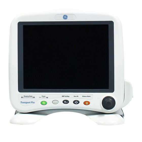
Equipment Overview: Views Views Front 602A Description Alarm light Controls and indicators Revision A Transport Pro 2012659-042... -
Page 18: Rear
Equipment Overview: Views Rear 603A Description Serial number label Video In (TRAM) connector Ethernet (Service) connector Main processor diagnostic LEDs (Light Emitting Diodes) Mounting points ePort connector TRAM chute mounting slots TRAM chute/monitor mounting slot Transport Pro Revision A 2012659-042... -
Page 19: Side
Equipment Overview: Views Side 604A, 606A Description DC power connector Video In connector TRAM module TRAM communication cable TRAM chute Cable management tray Battery doors Revision A Transport Pro 2012659-042... -
Page 20: Controls
Power and battery indicators are located on the control panel. Indicator Label DC power Battery power Battery charge status NOTE All control panel indicators illuminate as the monitor powers up or during changes between normal and standby mode. Transport Pro Revision A 2012659-042... -
Page 21: Dc Power
None The monitor is powered by the external power supply. The monitor is powered by both batteries simultaneously. Revision A Transport Pro 2012659-042... -
Page 22: Alarm Light
Ethernet connector. 607A Color Description Green There is communication with an acquisition device. Flashing Green The monitor is running the Boot Loader program. Yellow The main code is running. The boot code is running. 2-10 Transport Pro Revision A 2012659-042... -
Page 23: Connectors
The ePort connector will provide communication and power between acquisition devices and the monitor in future releases. Revision A Transport Pro 2-11 2012659-042... -
Page 24: Basic Components
The line voltage range of the external power supply is 100 to 240 V AC. TRAM Chute A TRAM chute is used to secure one TRAM module to the monitor during patient transport. 2-12 Transport Pro Revision A 2012659-042... -
Page 25: Tram Module
If the battery fails to meet the target performance, the battery charger will prompt you to condition the battery. If the battery does not hold a charge, then the battery charger will illuminate a “fail” light. Revision A Transport Pro 2-13 2012659-042... -
Page 26: Theory Of Operation
The processor/power management circuit board assembly consists of the processor/power management circuit board, LCD backlight inverter circuit board, alarm light circuit board, battery interface circuit board and speaker. These items are mounted in an open-ended sheet metal box for additional EMI shielding. 2-14 Transport Pro Revision A 2012659-042... -
Page 27: Lcd Backlight Inverter
It also controls battery status communication with the monitor. Speaker The speaker is used for audible notification of alarms. It is 66 mm square, water-resistant, 3 watt, with a frequency response of 400 to 4500 Revision A Transport Pro 2-15 2012659-042... - Page 28 Equipment Overview: Theory of Operation 2-16 Transport Pro Revision A 2012659-042...
-
Page 29: Installation
Installation Revision A Transport Pro 2012659-042... -
Page 30: Location Requirements
Do not install the monitor in a location where it may drop on the patient. All consoles and brackets used must have a raised edge. Transport Pro Revision A 2012659-042... -
Page 31: Battery
6. Confirm that the battery gauge displays. 7. Verify the green or amber battery Charging Status indicator is illuminated, if on AC power. Revision A Transport Pro 2012659-042... -
Page 32: Software
Mounting Options There are two mounting options, bedrail and IV pole. For mounting instructions, refer to the installation instructions included in the mounting kit. Transport Pro Revision A 2012659-042... -
Page 33: Configuration
Configuration Revision A Transport Pro 2012659-042... -
Page 34: Introduction
Many of the configuration settings do not take effect until the monitor is rebooted. To reboot the monitor, follow this procedure. 1. Hold down NBP Go/Stop and Zero All. 2. Press the TRIM KNOB control. 3. Release all when the display goes blank. Transport Pro Revision A 2012659-042... -
Page 35: Monitor Settings
1. Select MORE MENUS > MONITOR SETUP > SERVICE MODE. 2. Use the TRIM KNOB control to enter the service password. 3. Select MENU SETUP > MONITOR DEFAULTS PASSWD. 4. Select either REQUIRED or NOT REQUIRED. 5. Press the TRIM KNOB control to exit. Revision A Transport Pro 2012659-042... -
Page 36: Unit Name
5. Select SET BED NUMBER and press the TRIM KNOB control to exit. Country Selection The country selection defines a particular set of GE factory defaults. There are two options: DEFAULT or FRANCE. To select the country, follow this procedure. -
Page 37: Language
To select the language, follow this procedure. 1. Access the Boot Loader program. 2. Select SET CONFIGURATION > SET LANGUAGE. 3. Select the appropriate language. 4. Reboot the monitor to display the new language. Revision A Transport Pro 2012659-042... - Page 38 Configuration: Monitor Settings Transport Pro Revision A 2012659-042...
-
Page 39: Maintenance
Maintenance Revision A Transport Pro 2012659-042... -
Page 40: Maintenance Schedule
The manufacturer does not, in any manner, assume the responsibility for performing the recommended maintenance schedule, unless an Equipment Maintenance Agreement exists. The sole responsibility rests with the individuals, hospitals, or institutions utilizing the device. Transport Pro Revision A 2012659-042... -
Page 41: Maintenance Checklist
9-10. “Power Test” on page 9-11. “Battery Function Test” on page 9-12. “Video Test Screens” on page 9-13. “Brightness Level Test” on page 9-13. “Speaker Test” on page 9-13. “TRAM Communication Test” on page 9-13. Revision A Transport Pro 2012659-042... -
Page 42: Inspection And Cleaning
Never use the following solutions: Acetone Betadine Methylene chloride Methyl ethyl ketone Hexane Lysol Sporicidin Ammonia-based glass cleaners Alcohol-based cleaning agents Abrasive cleaners or solvents of any kind Never autoclave or steam clean the equipment. Transport Pro Revision A 2012659-042... -
Page 43: Cleaning Recommendations
As the battery ages, the full-charge capacity of the battery will degrade and be permanently lost. As a result, the amount of charge that is stored and available for use is reduced. The following terms are used to define the battery capacity: Revision A Transport Pro 2012659-042... -
Page 44: Use Recommendations
When the battery is stored inside a monitor that is continuously powered by AC power source and is not powered by battery on a regular basis, the life of the battery may be less than 12 months. GE recommends that you remove the battery and store it near the monitor until it is needed. -
Page 45: Internal
3. Charge the battery. Internal GE recommends using the Cadex SMart Two+ Charger to wake up a battery. To wake up a battery inside the monitor, follow this procedure. 1. Connect the external power supply to the DC power connector on the monitor. -
Page 46: Repair Log
Maintenance: Repair Log Repair Log Use the repair log to record the repair history of this product. Monitor Serial Number: Institution Name: Date Maintenance/Repair Technician Transport Pro Revision A 2012659-042... -
Page 47: Troubleshooting
Troubleshooting Revision A Transport Pro 2012659-042... -
Page 48: Overview
GE recommends formal service training before repairs are attempted. These troubleshooting procedures combined with training provide the service technician with skills necessary to service and repair a monitor in the event of a malfunction. -
Page 49: Alarms Light
If the power supply LED is on, check the connection to monitor. b. If the power supply LED is off, check the AC power cord connection. If all connections are good, replace the power supply. If problem persists, replace the main processor FRU. Revision A Transport Pro 2012659-042... -
Page 50: Display Dim
Display Bad Quality 1. Perform video test in the Boot Loader program. 2. If any of the video screens look bad, replace the display FRU. If all video screens look good, this is a customer preference issue. Transport Pro Revision A 2012659-042... -
Page 51: Missing/Inaccurate Patient Data/Waveforms
3. Reseat the keypad harness connection. 4. Verify that the keypad harness is not damaged. 5. If the keypad harness is damaged, replace the front bezel. 6. If the keypad harness is not damaged, replace the main processor FRU. Revision A Transport Pro 2012659-042... -
Page 52: Error Messages
“WARNING: The EEPROM data was found to be either INVALID or 1. Restore Ethernet address and IP address. uninitialized. GE factory defaults will be stored in both the EEPROM 2. Power cycle. and the monitor’s configuration memory. You will be required to re- 3. -
Page 53: Power Sources
Only persons responsible for configuring and maintaining the monitor should access the service menus. ALWAYS use caution when using any of these protected functions. Refer to “General” on page 4-2 for password, Boot Loader access and reboot instructions. Revision A Transport Pro 2012659-042... -
Page 54: Boot Loader Service Menu
Define if a password is required to access the Monitor Defaults menu. MONITOR SETTINGS Set the unit name and bed number. Review Errors The Review Errors menu is an advanced troubleshooting tool used by GE engineering personnel to review error logs. Transport Pro Revision A 2012659-042... - Page 55 FORCED RESET — The operating system restarted normally after a known condition, such as an Internet address change, patient discharge, etc. DATE The date the event or problem occurred. TIME The time the event or problem occurred. Revision A Transport Pro 2012659-042...
-
Page 56: Battery Service
1. Select MORE MENUS > MONITOR SETUP. 2. Select SERVICE MODE and enter the password. 3. Select BATTERY SERVICE. 622A NOTE If there is only one internal battery, no information will display in the Battery B column. 6-10 Transport Pro Revision A 2012659-042... -
Page 57: Ordering Parts
Ordering Parts Revision A Transport Pro 2012659-042... -
Page 58: Overview
If you require additional information or troubleshooting assistance, contact GE Technical Support. To order parts, contact Service Parts at the address or telephone number listed on the “How to Reach Us...” page found in the front of this manual. -
Page 59: Exploded View
Ordering Parts: Exploded View Exploded View 622A Revision A Transport Pro 2012659-042... -
Page 60: Field Replaceable Units
Bedrail hook mount kit 2007665-002 IV pole mounting kit 2021966-001 External power supply 2012183-001 Rechargeable lithium-ion battery (11.1 V) 2017857-002 Cadex SMart Two+ battery charger 2017857-002 Standard category 5 cross-over cable 415480-001 TRAM communication cable 403496-001 Transport Pro Revision A 2012659-042... -
Page 61: Hardware
Phillips-head screw M4 X 25 with thread lock Handle 2000543-001 Phillips-head screw M4 X 14 with thread lock TRAM chute 2000546-005 Phillips-head screw M4 X 20 with thread lock Battery housing 2000546-006 Phillips-head screw #4 X 0.31 Battery doors (2) 2000905-001 Revision A Transport Pro 2012659-042... - Page 62 Ordering Parts: Hardware Transport Pro Revision A 2012659-042...
-
Page 63: Disassembly
Disassembly Revision A Transport Pro 2012659-042... -
Page 64: Service Requirements
Any unauthorized attempt to repair equipment under warranty voids that warranty. It is the user’s responsibility to report the need for service to GE or to one of their authorized agents. Failure on the part of the responsible individual, hospital, or... -
Page 65: During Disassembly
Handle all PCB assemblies by their edges. These guidelines may not guaranty a 100% static-free workstation, but can greatly reduce the potential for failure of any electrical/ electronic assemblies being serviced. Revision A Transport Pro 2012659-042... -
Page 66: Back Plastic Replacement
1. Unplug the monitor from the AC power source. 2. Remove both batteries from the monitor. 3. Remove the TRAM module from the TRAM chute. 4. Remove the TRAM chute. 5. Remove the six screws from the back of the monitor. 603A Transport Pro Revision A 2012659-042... - Page 67 8. Lay both halves of the monitor on a flat work surface and hang the TRIM KNOB control over the edge of the work surface. 9. Disconnect the battery harness from the main processor PCB. 626A, 627A Revision A Transport Pro 2012659-042...
-
Page 68: Back Plastic Assembly
5. Secure the back plastic to the front plastic with the six screws (PN 402440-002). 6. Attach the TRAM chute to the foot with the screw (PN 2000546-005). 7. Insert the TRAM module into the TRAM chute. 8. Insert the batteries in the monitor. Transport Pro Revision A 2012659-042... -
Page 69: Fru Replacement
Remove the four screws holding the main processor PCB to the display assembly. 629A b. Pull out the backlight friction connector from the inverter PCB. Do not pull on the connector wires. 630A Squeeze the connector tabs and pull out the connector from the Revision A Transport Pro 2012659-042... - Page 70 PCB and display friction connectors to the main processor PCB. 5. Secure the main processor PCB to the display assembly with the four screws (PN 2000540-007). 6. Assemble the back plastic. See “Back Plastic Assembly” on page 8-6. Transport Pro Revision A 2012659-042...
-
Page 71: Main Processor Pcb Subassembly
3. Remove the battery harness from the back half of the monitor. 637A 4. Remove the display subassembly. See “Display Subassembly” page 8-7. 5. Remove the main processor PCB subassembly. Follow your country requirements for PCB disposal. Revision A Transport Pro 2012659-042... - Page 72 10. Reconnect the battery harness to the display subassembly. 11. Secure the battery housing to the back plastic with the seven screws (PN 409914-002 and 2000546-006). 12. Assemble the back plastic. See “Back Plastic Assembly” on page 8-6. 8-10 Transport Pro Revision A 2012659-042...
-
Page 73: Front Plastic Subassembly
PCB and display friction connectors to the main processor PCB. 6. Secure the main processor PCB to the display assembly with the four screws (PN 2000540-007). 7. Assemble the back plastic. See “Back Plastic Assembly” on page 8-6. Revision A Transport Pro 8-11 2012659-042... -
Page 74: Speaker
PCB and display friction connectors to the main processor PCB. 9. Secure the main processor PCB to the display assembly with the four screws (PN 2000540-007). 10. Assemble the back plastic. See “Back Plastic Assembly” on page 8-6. 8-12 Transport Pro Revision A 2012659-042... -
Page 75: Inverter Pcb
7. Secure the inverter board to the main processor PCB with the two screws (PN 2000540-007). 8. Reinstall the display subassembly. Be sure to reconnect the backlight friction, keypad PCB and display friction connectors to the main processor PCB. Revision A Transport Pro 8-13 2012659-042... -
Page 76: Alarm Light
4. Replace the alarm light PCB and alarm light harness. 5. Connect the alarm light cable harness to the alarm light PCB and main processor PCB. 6. Assemble the back plastic. See “Back Plastic Assembly” on page 8-6. 8-14 Transport Pro Revision A 2012659-042... -
Page 77: Eport Flex Circuit
8-9. 4. Remove the two screws attaching the flex circuit cable to the back plastic. 5. Replace the flex circuit. 6. Assemble the back plastic. See “Back Plastic Assembly” on page 8-6. Revision A Transport Pro 8-15 2012659-042... -
Page 78: Foot
1. Remove the two screws that attach the foot to the back plastic. 603A 2. Pull to slide the foot out of the grooves in the back plastic. 3. Slide the new foot into place and install the two screws (PN 2000540- 001). 8-16 Transport Pro Revision A 2012659-042... -
Page 79: Battery Doors
1. Remove the battery door screws and battery doors. 604A 2. Insert battery door B into the top position 3. Insert battery door A into the bottom position. 4. Insert and tighten the two battery door screws (PN 2000905-001). Revision A Transport Pro 8-17 2012659-042... -
Page 80: Handle
1. Remove the four screws that connect handle to the display. 603A 2. Remove the handle. 3. Align new handle and press firmly into place. You will hear a snap when in place. 4. Secure with the four screws (PN 2000543-001) 8-18 Transport Pro Revision A 2012659-042... -
Page 81: Tram
TRAM chute mounting screw from the foot. b. Slide the TRAM chute to the right to release the mounting tabs from the display. 640A 3. Align the new, empty TRAM chute with the mounting slots. Revision A Transport Pro 8-19 2012659-042... - Page 82 7. Insert the TRAM communication cable into Video In connector on the left side of the monitor. 8. Insert the other end of the TRAM communication cable into the TRAM module’s DISPLAY (DISPL) connector on the front of the TRAM module. 8-20 Transport Pro Revision A 2012659-042...
-
Page 83: Checkout
Checkout Revision A Transport Pro 2012659-042... -
Page 84: Electrical Safety Tests
The sole responsibility rests with the individual or institution using the equipment. GE service personnel may, at their discretion, follow the procedures provided in this manual as a guide during visits to the equipment site. -
Page 85: Power Outlet
Each time the main enclosure is disassembled or a circuit board is removed, tested, repaired, or replaced. Record the date and results on the “For the latest PM form for this product, contact GE Service.” on page 9-14 Power Outlet Before starting the tests, the power outlet from which the monitoring device will get electrical power must be checked. -
Page 86: Ground (Earth) Integrity
This test unlike a ground continuity test will also stress the ground system by using special ground bond testers. This test normally is only required as a manufacturing production test to receive safety agency compliance (i.e. EN 60601-1). Transport Pro Revision A 2012659-042... -
Page 87: Ground (Earth) Wire Leakage Current
NOTE When testing the monitor, the device under test includes the optional external power supply. The device under test is to be tested at its normal operating voltage. Revision A Transport Pro 2012659-042... -
Page 88: Enclosure Leakage Current
6. Read the current leakage indicated on DMM. NOTE If either reading is greater than the appropriate specification below or the device under test fails, contact GE Technical Support. 300 µA (0.3 volts on the DMM), and the device under test is powered from 100-120 V/50-60 Hz 300 µA (0.3 volts on the DMM), and the device under test is... - Page 89 6. Read the current leakage indicated on DMM. NOTE If either reading is greater than the appropriate specification below or the device under test fails, contact GE Technical Support. • 300 µA (0.3 volts on the DMM), and the device under test is powered from 100-120 V/50-60 Hz •...
-
Page 90: Patient (Source) Leakage Current
NOTE If either reading is greater than 50 µA (0.05 volts on the DMM), the device fails this test. Contact GE Technical Support. 7. Change the GND switch to the Closed position. 8. Read the leakage current indicated on the DMM. -
Page 91: Patient (Sink) Leakage Current
NOTE If either reading is greater than the appropriate specification below, the device under test fails. Contact GE Technical Support. 10 µA (0.01 volts on the DMM) at 120 V AC using the test body. 20 µA (0.02 volts on the DMM) at 240 V AC using the test body. -
Page 92: Power Cord And Plug
9-13. “TRAM Communication Test” on page 9-13. Flex circuit “Power Test” on page 9-11. “Battery Function Test” on page 9-12. “TRAM Communication Test” on page 9-13. TRAM “TRAM Communication Test” on page 9-13. 9-10 Transport Pro Revision A 2012659-042... -
Page 93: Required Tools/Equipment
If the DC power indicator is on, continue with the tests. If either of the Charging Status indicators is yellow, wait for the batteries to fully charge and the indicators to illuminate Revision A Transport Pro 9-11 2012659-042... -
Page 94: Battery Function Test
AC power source. 7. Verify the CHARGING STATUS indicator illuminates for a few minutes. An amber glow indicates the monitor’s battery is charging. A green glow indicates the monitor’s batteries are fully charged. 9-12 Transport Pro Revision A 2012659-042... -
Page 95: Video Test Screens
5. Place the TRAM module into the chute. 6. Configure the display with as many waveforms as possible. Refer to the operator's manual, if necessary. 7. Verify that the waveforms look clean (no noise). Revision A Transport Pro 9-13 2012659-042... -
Page 96: Completion
PM form. Also include comments regarding any unusual environmental conditions that may affect the operation or reliability of the equipment in the area provided on the PM form. For the latest PM form for this product, contact GE Service. 9-14 Transport Pro... -
Page 97: Technical Specifications
Technical Specifications Revision A Transport Pro 2012659-042... -
Page 98: Physical
Meets EN 60601-2-27 IPX0 Drop test standard Meets EN 60601-1 from 76.2 cm (30 inches) Certification UL 60601-1 classified. UL classified for CAN/CSA C22.2 No. 601.1 EN 60601-1 certified CE marking for Council Directive 93/42/EEC Medical Device Directive Transport Pro Revision A 2012659-042... -
Page 99: Display
4 hours Battery life 500 cycles to 50% capacity Storage temperature -20 to 60°C (-4 t0 140°F) External Power Supply Input 100-240 V AC, 50/60 Hz single phase Output 16.75 VDC at 4 amps Revision A Transport Pro 2012659-042... - Page 100 Technical Specifications: External Power Supply Transport Pro Revision A 2012659-042...
-
Page 101: Electromagnetic Compatibility
Electromagnetic Compatibility Revision A Transport Pro 2012659-042... -
Page 102: Electromagnetic Compatibility (Emc
Guidance and Manufacturer’s Declaration – Electromagnetic Emissions The Transport Pro system is intended for use in the electromagnetic environment specified below. It is the responsibility of the customer or user to assure that the system is used in such an environment. -
Page 103: Guidance And Manufacturer's Declaration - Electromagnetic Immunity
Power frequency magnetic fields should be at levels (50/60 Hz) characteristic of a typical location in a typical Magnetic Field commercial or hospital environment. EN 61000-4-8 NOTE: is the AC mains voltage prior to application of the test level. Revision A Transport Pro 2012659-042... - Page 104 If abnormal performance is observed, additional measures may be necessary, such as re-orienting or relocating the equipment. Over the frequency range 150 KHz to 80 MHz, field strengths should be less than 3 V/m. Transport Pro Revision A 2012659-042...
-
Page 105: Recommended Separation Distances
P is the maximum output power rating of the transmitter in watts (W) according to the transmitter manufacturer. NOTE: These guidelines may not apply in all instances. Electromagnetic propagation is affected by absorption and reflection from structures, objects and people. Revision A Transport Pro 2012659-042... -
Page 106: Compliant Cables And Accessories
The tables below list cables, transducers, and other applicable accessories with which GE claims EMC compliance. Any supplied accessories that do not affect EMC compliance are not included. Part No Description... - Page 107 Edwards Truwave Adapter Cable 3.6 m / 12 ft 2016995-00X Spectramed Transducer Adapter Cable 3.6 m / 12 ft Utah Disposable Transducers (DPT, DP2, DP3) Spectramed Transducers (TC-MQ) Abbott Transpac-IV Transducers Edwards Truwave Transducers (PX) Revision A Transport Pro 2012659-042...
- Page 108 Accessories 2006171-00X TRAM Module Series 403496-001 TRAM Communication Cable 4.5 m / 15 ft RJ45 series Category 5 cable 2017857-002 Battery Lithium-Ion 2012183-001 DC Power Supply 2000633-001 Defib Sync Cable 3.0 m / 10 ft Transport Pro Revision A 2012659-042...
- Page 110 Asia Headquarters World Headquarters GE Medical Systems GE Medical Systems GE Medical Systems Information Technologies GmbH Information Technologies Asia; GE (China) Co., Ltd. Information Technologies, Inc. Munzinger Straße 3-5 24th Floor, Shanghai MAXDO Center, 8200 West Tower Avenue D-79111 Freiburg...
Need help?
Do you have a question about the Transport Pro and is the answer not in the manual?
Questions and answers