Table of Contents
Advertisement
Quick Links
Advertisement
Table of Contents

Related Manuals for SimonsVoss Digital Cylinder AX

Summary of Contents for SimonsVoss Digital Cylinder AX
- Page 1 Digital Cylinder AX (Z5) Manual 11.01.2022...
-
Page 2: Table Of Contents
Contents Digital Cylinder AX (Z5) (Manual) 2 / 158 Contents Intended use .............................. 5 General safety instructions........................ 6 Product-specific safety instructions.................... 9 AP-specific safety instructions...................... 11 Structure .............................. 12 Mechanical thumb-turn.......................... 13 Electronic thumb-turn .......................... 13 Comfort cylinder (CO; reader on one side).................. 14 Freely-rotating cylinder (FD; reader on both sides).............. 14 Half cylinder (HZ, reader on one side).................... - Page 3 Contents Digital Cylinder AX (Z5) (Manual) 3 / 158 7.2.5 Thumb-turns .......................... 29 Programming.............................. 31 Installation .............................. 33 Brief descriptions (entire assembly) .................... 33 9.1.1 Comfort cylinder/anti-panic cylinder (CO/AP, reader on one side).... 33 9.1.2 Freely-rotating cylinder (FD; reader on both sides) ............ 34 9.1.3 Half cylinder (HZ, reader on one side)................ 35 9.1.4...
- Page 4 Contents Digital Cylinder AX (Z5) (Manual) 4 / 158 12.2 Cleaning and disinfection........................ 149 Technical specifications ........................ 150 13.1 Euro Profile and SwissRound........................ 150 13.2 Scandinavian Oval Scandinavian Round.................. 151 13.3 Dimensions.............................. 153 EU/UK Declaration of conformity..................... 156 Help and other information ........................ 157...
-
Page 5: Intended Use
1. Intended use Digital Cylinder AX (Z5) (Manual) 5 / 158 1 Intended use You can install AX digital locking cylinders (Z5) in door locks designed for this purpose (e.g. DIN mortise locks) and integrate them into a digital locking system. -
Page 6: General Safety Instructions
Blocked access Access through a door may stay blocked due to incorrectly fitted and/or in- correctly programmed components. SimonsVoss Technologies GmbH is not liable for the consequences of blocked access such as access to in- jured or endangered persons, material damage or other damage! - Page 7 2. General safety instructions Digital Cylinder AX (Z5) (Manual) 7 / 158 CAUTION Fire hazard posed by batteries The batteries used may pose a fire or burn hazard if handled incorrectly. 1. Do not try to charge, open, heat or burn the batteries.
- Page 8 Only trained personnel may install and commission the product. Incorrect installation SimonsVoss Technologies GmbH accepts no liability for damage caused to doors or compon- ents due to incorrect fitting or installation. Modifications or further technical developments cannot be excluded and may be implemented without notice.
-
Page 9: Product-Specific Safety Instructions
Damage to the AX locking cylinder due to unsuitable tools Special tools are required to open the cover and dismantle the AX locking cylinder. If you use un- suitable tools, you may damage the AX locking cylinder. Only use the separately available SimonsVoss special tool ( Accessories [ 25]... - Page 10 3. Do not use your Digital Cylinder AX with MIFARE Classic, PinCode keypad, BLE or WaveNet. Fire resistance The fire resistance of the Digital Cylinder AX tested according to DIN EN 1634-2: 2009:05 for fire and smoke resistant doors (type: wood and wood-product fire protection doors with a resistance time of 90 minutes).
-
Page 11: Ap-Specific Safety Instructions
4. AP-specific safety instructions Digital Cylinder AX (Z5) (Manual) 11 / 158 4 AP-specific safety instructions For locking cylinders with anti-panic function, also observe the following safety instructions: WARNING Failure of the escape door function The use of unsuitable components or components that are not ready for operation can impair the function of an escape door. -
Page 12: Structure
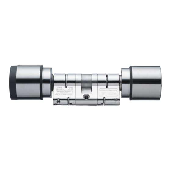
(Manual) 12 / 158 5 Structure The Digital Cylinder AX has a modular construction. It always consists of a cylinder profile with drill protection and actuator integrated in the core with an external thumb-turn and optionally an internal thumb-turn. The knobs are removable. However, the thumb-turn mounts of the electronic and mechanical thumb-turns are not compatible with each other. -
Page 13: Mechanical Thumb-Turn
5. Structure Digital Cylinder AX (Z5) (Manual) 13 / 158 5.1 Mechanical thumb-turn The mechanical knob is a single component. It consists of the knob housing with embossed logo and two magnetic pins for assembly and disassembly. 5.2 Electronic thumb-turn The electronic thumb-turn is composed of several components. -
Page 14: Comfort Cylinder (Co; Reader On One Side)
5. Structure Digital Cylinder AX (Z5) (Manual) 14 / 158 5.3 Comfort cylinder (CO; reader on one side) The comfort cylinder consists of: a mechanical thumb-turn an electronic thumb-turn a cylinder profile 5.4 Freely-rotating cylinder (FD; reader on both sides) -
Page 15: Half Cylinder (Hz, Reader On One Side)
a cylinder profile 5.5.1 Scandinavian Oval (SO) The Digital Cylinder AX for SO mortise locks is structured similarly to a half cylinder and consists of: an electronic thumb-turn a cylinder profile with tappet ... -
Page 16: Scandinavian Round - (Rs)
Digital Cylinder AX (Z5) (Manual) 16 / 158 5.5.2 Scandinavian Round – (RS) The Digital Cylinder AX for RS mortise locks is structured similarly to a half cylinder and consists of: an electronic thumb-turn a cylinder profile with tappet ... -
Page 17: Basic Configuration, Profiles And Features
6. Basic configuration, profiles and fea- tures Digital Cylinder AX (Z5) (Manual) 17 / 158 6 Basic configuration, profiles and features The Digital Cylinder AX is available in different versions: Comfort cylinder (freely- rotating, one-sided mech- anical) [ 17] Freely rotating (freely ro- Basic configuration [ 17]... -
Page 18: Freely-Rotating Cylinder (Fd; Reader On Both Sides)
6.1.3.1 Scandinavian Oval (SO) 6.1.3.2 Scandinavian Round – (RS) 6.2 Profiles 6.2.1 Standard Euro profile cylinder as per to DIN 18525 / EN1303 In this version, the Digital Cylinder AX is supplied with a cylinder profile for Euro profile cylinders. -
Page 19: Swiss Round (Sr)
(Manual) 19 / 158 6.2.2 Swiss round (SR) In this version, the Digital Cylinder AX is supplied with a cylinder profile for Swiss Round. 6.2.3 Scandinavian oval (SO) In this version, the Digital Cylinder AX is supplied with a cylinder profile for Scandinavian Oval. -
Page 20: Versions
For doors built along escape routes after April 2003, the following points must be observed: All closures for which the approvals state that the Digital Cylinder AX does no affect the function of the lock, all Digital Cylinder AX can be used. -
Page 21: Access Control (Zk)
DANGER Due to the structural properties of panic locks, it is not permitted to turn the knob of the Digital Cylinder AX to the stop, as this can affect the lock’s panic function. CAUTION Use of the anti-panic version of the locking cylinder in non-approved... -
Page 22: Brass Version (Ms)
This option equips the Digital Cylinder AX with additional seals. The Digital Technical specifications [ 150] Cylinder AX is therefore waterproof (see You can now also use the Digital Cylinder AX with this option outside for external doors or other areas exposed to high humidity (e.g. washrooms or bathrooms). IMPORTANT... -
Page 23: Multi-Point (Mr)
Cylinder AX is supplied to you fitted with two LockNodes. 6.3.6 Multi-point (MR) This option equips your Digital Cylinder AX with a locking bit with dedicated points. The locking bit engages at these points when disengaged. If you have a smooth-running lock with multi-point locking, you should use this option. - Page 24 B or C certified according to VdS/SKG (DIN 18257 class ES 2 or ES 3). 2. Make sure that the Digital Cylinder AX does not protrude more than 3 3. Do not use your Digital Cylinder AX with MIFARE Classic, PinCode...
-
Page 25: Accessories
7. Accessories Digital Cylinder AX (Z5) (Manual) 25 / 158 7 Accessories 7.1 Special tools Product Description Item order code You can use this special tool to: Dismantle thumb-turns. Remove the cover of the Special tool Z5.TOOL electronic thumb-turn. -
Page 26: Components
(LockNode) into the cover of the battery compartment (see 51] The Digital Cylinder AX then also supplies the LockNode with energy with its batteries. A spring-loaded pin contacts the reader thumb-turn cover after assembly to communicate wirelessly similarly to an antenna. - Page 27 7. Accessories Digital Cylinder AX (Z5) (Manual) 27 / 158 Plastic cap with metal ring for active cylinder (SV-Z5.TT.CAP.R) Plastic cap for active cylinder With metal ring and integrated antenna for use with a LockNode (SV-Z5.TT.CAP.R.AN) Full metal cap for active cylinder (SV-Z5.TT.CAP.S)
-
Page 28: Length Modularity
7. Accessories Digital Cylinder AX (Z5) (Manual) 28 / 158 7.2.3 Length modularity Core extension for the Extension bolt Profile extension profile Z5.PROFILE.05: 5 mm Z5.CORE.05: 5 mm Z5.BOLT.XX (XX = Z5.PROFILE.10: 10 required basic Z5.CORE.10: 10 mm ... - Page 29 7. Accessories Digital Cylinder AX (Z5) (Manual) 29 / 158 The core extension for your Digital Cylinder AX is available in various lengths: Z5.KA: 8 mm Z5.KA.12: 12mm Core extension [ 113] For more information see 7.2.5 Thumb-turns Inside thumb-turn The inside thumb-turn (SV-Z5.TT.IN) is also available separately for your...
- Page 30 Digital Cylinder AX (Z5) (Manual) 30 / 158 The escape thumb-turn for the Digital Cylinder AX is equipped with a ratchet function. It replaces the inside thumb-turn of a comfort cylinder. Unlocking from inside possible at any time without an identification ...
-
Page 31: Programming
31 / 158 8 Programming NOTE Freely rotating active/hybrid Digital Cylinder AX only with shortened range With freely rotating cylinders, the reader knobs may not have sufficient clearance at low cylinder lengths. Due to the range of the active techno- logy, the radio signal can also be unintentionally received by the second reader knob. - Page 32 8. Programming Digital Cylinder AX (Z5) (Manual) 32 / 158 NOTE Duration of initial programming A large amount of data is transferred during initial programming. The data transfer speed is significantly higher with a SmartStick AX or a SmartCD.MP (and the programming time is therefore shorter).
-
Page 33: Installation
9.1.1 Comfort cylinder/anti-panic cylinder (CO/AP, reader on one side) 9.1.1.1 Standard assembly/initial assembly This is the easiest way to install the Digital Cylinder AX . You do not need any special tools for the initial assembly. Remove the red plastic assembly lock before initial assembly. -
Page 34: Freely-Rotating Cylinder (Fd; Reader On Both Sides)
Digital Cylinder AX is fitted. 9.1.1.2 Fitting with clip-on covers This option allows you to combine the Digital Cylinder AX with specific panels. Some cover plates are mounted on the cylinder and so are located between the thumb-turn and the door. If you want to use such panels, you have to dismantle both thumb-turns. -
Page 35: Half Cylinder (Hz, Reader On One Side)
7. Also fit the other electronic knob. 8. Carry out a functional test (see Functional test [ 47] Digital Cylinder AX is fitted with clip-on covers. 9.1.3 Half cylinder (HZ, reader on one side) 9.1.3.1 Standard mounting Special tool available. -
Page 36: Scandinavian Oval/Round (So/Rs)
9. Installation Digital Cylinder AX (Z5) (Manual) 36 / 158 9.1.4 Scandinavian oval/round (SO/RS) 9.1.4.1 Installation IMPORTANT Unauthorised access by drilling on the inside The outside of the AX locking cylinder is equipped with drilling protection on the outside, depending on the version. -
Page 37: Detailed Descriptions (Individual Steps)
9. Installation Digital Cylinder AX (Z5) (Manual) 37 / 158 9.2 Detailed descriptions (individual steps) 9.2.1 Mounting thumb-turn (mech.) 1. Attach the thumb turn. 2. The thumb-turn snaps into place with one click. Mechanical thumb-turn is installed. Disassembling the mechanical thumb-turn... -
Page 38: Unmounting The Thumb-Turn (Mech.)
9. Installation Digital Cylinder AX (Z5) (Manual) 38 / 158 9.2.2 Unmounting the thumb-turn (mech.) Special tool available. ü 1. Align the thumb turn horizontally. 2. Attach the special tool. 3. Align the special tool so that the logo is parallel to the recess. - Page 39 9. Installation Digital Cylinder AX (Z5) (Manual) 39 / 158 4. At the same time turn the special tool and the thumb turn counter- clockwise. 5. Remove the special tool and the thumb turn at the same time. The mechanical thumb turn is disassembled.
-
Page 40: Mounting Thumb-Turn (Electr.)
9. Installation Digital Cylinder AX (Z5) (Manual) 40 / 158 9.2.3 Mounting thumb-turn (electr.) 1.5 mm hexagonal wrench available. ü 1. Align the thumb turn mount horizontally. 2. Attach the thumb turn. - Page 41 9. Installation Digital Cylinder AX (Z5) (Manual) 41 / 158 NOTE Use the supplied hexagonal wrench. The special tool is supplied with a hexagonal wrench. Use this hexagonal wrench to mount and dismount the electronic thumb turn. 3. Insert the hexagonal wrench into the hole provided until it stops.
- Page 42 9. Installation Digital Cylinder AX (Z5) (Manual) 42 / 158 5. Pull out the hexagon wrench again. 6. Put on the cover.
-
Page 43: Unmounting The Thumb-Turn (Electr.)
9. Installation Digital Cylinder AX (Z5) (Manual) 43 / 158 7. Turn the cover clockwise. The cover snaps into place with one click. The electronic thumb turn is installed. 9.2.4 Unmounting the thumb-turn (electr.) NOTE Use the supplied hexagonal wrench. - Page 44 9. Installation Digital Cylinder AX (Z5) (Manual) 44 / 158 ü Special tool available. 1.5 mm hexagonal wrench available. ü 1. Align the thumb turn horizontally. 2. Attach the special tool. 3. Align the special tool so that the logo is parallel to the recess.
- Page 45 9. Installation Digital Cylinder AX (Z5) (Manual) 45 / 158 4. Hold the special tool and thumb turn cap firmly at the same time and turn them together 1-2° clockwise first and then counter-clockwise. NOTE Slipping when turning The surface of the thumb turn cap can be slippery and the cap can be diffi- cult to turn (especially with WP versions, recognizable by the blue cylinder neck ring or the lasered marking on the inner side of the cylinder profile).
- Page 46 9. Installation Digital Cylinder AX (Z5) (Manual) 46 / 158 7. Turn the hex wrench 270 degrees counterclockwise. 8. Pull out the hexagon wrench again.
-
Page 47: Functional Test
2. Turn the electronic thumb-turns. The Digital Cylinder AX the AX locking cylinder must not be tight, nor rotate the tappet. 3. Activate an authorised identification medium. 4. Check that the Digital Cylinder AX engages and pushes out the locking bit. Mounting or battery change successfully completed. - Page 48 9. Installation Digital Cylinder AX (Z5) (Manual) 48 / 158 O section: 15° to 345° 345° 15° (15)° (15)° R section: R section: 210° to 345° 15° to 150° 210° 150° U section: 150° to 210° U section: No restore force on the cam...
-
Page 49: Insert Locking Cylinder
The test is to be repeated after the fault has been eliminated as described above. 9.2.7 Insert locking cylinder The Digital Cylinder AX is modular. You can disassemble both the mechanical and electronic thumb-turn. Accordingly, you have the choice: Digital Cylinder AX inserted with the mechanical side ... -
Page 50: Fixing The Locking Cylinder
9. Installation Digital Cylinder AX (Z5) (Manual) 50 / 158 You have positioned the AX locking cylinder in the lock. 9.2.8 Fixing the locking cylinder Screw the locking cylinder AX tight with the face plate screw. Locking cylinder AX is fixed in the lock. -
Page 51: Customise Cylinder Ax
10. Customise Cylinder AX Digital Cylinder AX (Z5) (Manual) 51 / 158 10 Customise Cylinder AX 10.1 LockNode NOTE Full metal cap only suitable for active technology The full metal cap shields against high-frequency electromagnetic radi- ation, i.e. the reader thumb-turn can no longer be activated with WaveNet, smart cards (RFID) or BLE. - Page 52 10. Customise Cylinder AX Digital Cylinder AX (Z5) (Manual) 52 / 158 2. Attach the special tool. 3. Align the special tool so that the logo is parallel to the recess. 4. Hold the special tool and thumb turn cap firmly at the same time and turn them together 1-2°...
-
Page 53: Installation
10. Customise Cylinder AX Digital Cylinder AX (Z5) (Manual) 53 / 158 5. Remove the tool and cover. Cap is disassembled. 10.1.2 Installation 1. Push the latch inward and open the battery cover. - Page 54 10. Customise Cylinder AX Digital Cylinder AX (Z5) (Manual) 54 / 158 2. Slide the LockNode into the guides provided as shown.
-
Page 55: Attach The Cap
10. Customise Cylinder AX Digital Cylinder AX (Z5) (Manual) 55 / 158 3. Close the battery cover and LockNode. The locking device bleeps and flashes red four times. LockNode is installed. 10.1.3 Attach the cap ü Special tool available. 1. Put on the cover. -
Page 56: Replacement Caps
10. Customise Cylinder AX Digital Cylinder AX (Z5) (Manual) 56 / 158 2. Turn the cover clockwise. The cover snaps into place with one click. 10.2 Replacement caps The caps can be replaced without removing or programming the Digital Cylinder AX . -
Page 57: Remove Cap
10. Customise Cylinder AX Digital Cylinder AX (Z5) (Manual) 57 / 158 10.2.1 Remove cap Special tool available. ü 1. Align the thumb turn horizontally. 2. Attach the special tool. 3. Align the special tool so that the logo is parallel to the recess. - Page 58 10. Customise Cylinder AX Digital Cylinder AX (Z5) (Manual) 58 / 158 4. Hold the special tool and thumb turn cap firmly at the same time and turn them together 1-2° clockwise first and then counter-clockwise. NOTE Slipping when turning...
-
Page 59: Attach The Cap
10. Customise Cylinder AX Digital Cylinder AX (Z5) (Manual) 59 / 158 10.2.2 Attach the cap Special tool available. ü 1. Put on the cover. -
Page 60: Length Modularity
10. Customise Cylinder AX Digital Cylinder AX (Z5) (Manual) 60 / 158 2. Turn the cover clockwise. The cover snaps into place with one click. 10.3 Length modularity 10.3.1 Extend Cylinder AX The core extension and profile extension must be the same length. You... - Page 61 10. Customise Cylinder AX Digital Cylinder AX (Z5) (Manual) 61 / 158 ü Extractor for releasing the clamp Spacer for aligning the extension bolt ü Clamp block for pressing in the clamp ü 1. Place the Cylinder AX in the thumb-turn assembly tool.
- Page 62 10. Customise Cylinder AX Digital Cylinder AX (Z5) (Manual) 62 / 158 2. Hook the tip of the extractor into the clamp. 3. Lever the clamp out of the profile cylinder by moving the extractor to the centre of the cylinder.
- Page 63 10. Customise Cylinder AX Digital Cylinder AX (Z5) (Manual) 63 / 158 4. Pull the clamp completely out of the profile cylinder.
- Page 64 10. Customise Cylinder AX Digital Cylinder AX (Z5) (Manual) 64 / 158 5. Disassemble the two cylinder halves.
- Page 65 10. Customise Cylinder AX Digital Cylinder AX (Z5) (Manual) 65 / 158 6. Use the extractor to unscrew the extension bolt. 7. Insert suitable core extensions.
- Page 66 10. Customise Cylinder AX Digital Cylinder AX (Z5) (Manual) 66 / 158 8. Attach suitable profile extensions. 9. Place the spacer.
- Page 67 10. Customise Cylinder AX Digital Cylinder AX (Z5) (Manual) 67 / 158 10. Screw in a suitable extension bolt with the extractor until it rests on the spacer. NOTE Length on bolt head You will find a number on the bolt head. This number is the length of the...
- Page 68 10. Customise Cylinder AX Digital Cylinder AX (Z5) (Manual) 68 / 158 11. Reassemble the two cylinder halves. Extension bolt is protected against twisting.
- Page 69 10. Customise Cylinder AX Digital Cylinder AX (Z5) (Manual) 69 / 158 12. Pull the spacer off again.
- Page 70 10. Customise Cylinder AX Digital Cylinder AX (Z5) (Manual) 70 / 158 13. Push the halves together completely.
- Page 71 10. Customise Cylinder AX Digital Cylinder AX (Z5) (Manual) 71 / 158 14. Place the clip back into the slot of the profile cylinder with its lug facing the fastening screw and press the clamp with your thumb so that it can no longer fall out.
- Page 72 10. Customise Cylinder AX Digital Cylinder AX (Z5) (Manual) 72 / 158 The lever of the clamping block is reinforced at one point with a metal plate. The bracket that was previously inserted lies opposite this metal plate. 16. Push the clamp block lever towards the base plate until the clamp is fully seated in the profile cylinder.
-
Page 73: Shorten Cylinder Ax
10. Customise Cylinder AX Digital Cylinder AX (Z5) (Manual) 73 / 158 10.3.2 Shorten Cylinder AX You need a bolt for the desired length. Extractor for releasing the clamp ü ü Spacer for aligning the bolt ü Clamp block for pressing in the clamp... - Page 74 10. Customise Cylinder AX Digital Cylinder AX (Z5) (Manual) 74 / 158 2. Hook the tip of the extractor into the clamp. 3. Lever the clamp out of the profile cylinder by moving the extractor to the centre of the cylinder.
- Page 75 10. Customise Cylinder AX Digital Cylinder AX (Z5) (Manual) 75 / 158 4. Pull the clamp completely out of the profile cylinder.
- Page 76 10. Customise Cylinder AX Digital Cylinder AX (Z5) (Manual) 76 / 158 5. Disassemble the two cylinder halves.
- Page 77 10. Customise Cylinder AX Digital Cylinder AX (Z5) (Manual) 77 / 158 6. Unscrew the bolt with the extractor. 7. Remove the profile extension.
- Page 78 10. Customise Cylinder AX Digital Cylinder AX (Z5) (Manual) 78 / 158 8. Remove the core extension. 9. Place the spacer.
- Page 79 10. Customise Cylinder AX Digital Cylinder AX (Z5) (Manual) 79 / 158 10. Screw in a suitable bolt with the extractor until it rests on the spacer. NOTE Length on bolt head You will find a number on the bolt head. This number is the length of the...
- Page 80 10. Customise Cylinder AX Digital Cylinder AX (Z5) (Manual) 80 / 158 11. Reassemble the two cylinder halves. Bolt is protected against twisting.
- Page 81 10. Customise Cylinder AX Digital Cylinder AX (Z5) (Manual) 81 / 158 12. Pull the spacer off again.
- Page 82 10. Customise Cylinder AX Digital Cylinder AX (Z5) (Manual) 82 / 158 13. Push the halves together completely.
- Page 83 10. Customise Cylinder AX Digital Cylinder AX (Z5) (Manual) 83 / 158 14. Refit the clip into the slot of the profile cylinder with the lug facing the fastening screw. 15. Insert the cylinder into the clamping block so that the profile cylinder...
- Page 84 10. Customise Cylinder AX Digital Cylinder AX (Z5) (Manual) 84 / 158 The lever of the clamping block is reinforced at one point with a metal plate. The bracket that was previously inserted lies opposite this metal plate. 16. Push the clamp block lever towards the base plate until the clamp is fully seated in the profile cylinder.
-
Page 85: Combine Co Cylinders To Fd
10. Customise Cylinder AX Digital Cylinder AX (Z5) (Manual) 85 / 158 10.3.3 Combine CO cylinders to FD You can assemble a freely rotating AX cylinder from two AX comfort cylinders. ü Extractor for releasing the clamp Spacer for aligning the extension bolt ü... - Page 86 10. Customise Cylinder AX Digital Cylinder AX (Z5) (Manual) 86 / 158 2. Hook the tip of the extractor into the clamp.
- Page 87 10. Customise Cylinder AX Digital Cylinder AX (Z5) (Manual) 87 / 158 3. Lever the clamp out of the profile cylinder by moving the extractor to the centre of the cylinder.
- Page 88 10. Customise Cylinder AX Digital Cylinder AX (Z5) (Manual) 88 / 158 4. Pull the clamp completely out of the profile cylinder.
- Page 89 10. Customise Cylinder AX Digital Cylinder AX (Z5) (Manual) 89 / 158 5. Disassemble the two cylinder halves. First cylinder half prepared with centre piece and tappet piece.
- Page 90 10. Customise Cylinder AX Digital Cylinder AX (Z5) (Manual) 90 / 158...
- Page 91 10. Customise Cylinder AX Digital Cylinder AX (Z5) (Manual) 91 / 158 6. Place the second comfort cylinder AX in the thumb-turn assembly tool with the electronic thumb-turn facing upwards.
- Page 92 10. Customise Cylinder AX Digital Cylinder AX (Z5) (Manual) 92 / 158 7. Hook the tip of the extractor into the clamp.
- Page 93 10. Customise Cylinder AX Digital Cylinder AX (Z5) (Manual) 93 / 158 8. Lever the clamp out of the profile cylinder by moving the extractor to the centre of the cylinder.
- Page 94 10. Customise Cylinder AX Digital Cylinder AX (Z5) (Manual) 94 / 158 9. Pull the clamp completely out of the profile cylinder.
- Page 95 10. Customise Cylinder AX Digital Cylinder AX (Z5) (Manual) 95 / 158 10. Disassemble the two cylinder halves. Second cylinder half prepared without centre piece.
- Page 96 10. Customise Cylinder AX Digital Cylinder AX (Z5) (Manual) 96 / 158...
- Page 97 10. Customise Cylinder AX Digital Cylinder AX (Z5) (Manual) 97 / 158 11. Place the first cylinder half on the second cylinder half.
- Page 98 10. Customise Cylinder AX Digital Cylinder AX (Z5) (Manual) 98 / 158 12. Refit the clip into the slot of the profile cylinder with the lug facing the fastening screw. 13. Insert the cylinder into the clamping block so that the profile cylinder...
- Page 99 10. Customise Cylinder AX Digital Cylinder AX (Z5) (Manual) 99 / 158 The lever of the clamping block is reinforced at one point with a metal plate. The bracket that was previously inserted lies opposite this metal plate. 14. Push the clamp block lever towards the base plate until the clamp is fully seated in the profile cylinder.
-
Page 100: Reduce Co Cylinders To Hz
Digital Cylinder AX (Z5) (Manual) 100 / 158 NOTE Freely rotating active/hybrid Digital Cylinder AX only with shortened range With freely rotating cylinders, the reader knobs may not have sufficient clearance at low cylinder lengths. Due to the range of the active techno- logy, the radio signal can also be unintentionally received by the second reader knob. - Page 101 10. Customise Cylinder AX Digital Cylinder AX (Z5) (Manual) 101 / 158 ü Extractor for releasing the clamp Spacer for aligning the extension bolt ü Clamp block for pressing in the clamp ü ü Half Cylinder Center Section 1. Place the Cylinder AX in the thumb-turn assembly tool with the elec-...
- Page 102 10. Customise Cylinder AX Digital Cylinder AX (Z5) (Manual) 102 / 158 2. Hook the tip of the extractor into the clamp.
- Page 103 10. Customise Cylinder AX Digital Cylinder AX (Z5) (Manual) 103 / 158 3. Lever the clamp out of the profile cylinder by moving the extractor to the centre of the cylinder.
- Page 104 10. Customise Cylinder AX Digital Cylinder AX (Z5) (Manual) 104 / 158 4. Pull the clamp completely out of the profile cylinder.
- Page 105 10. Customise Cylinder AX Digital Cylinder AX (Z5) (Manual) 105 / 158 5. Disassemble the two cylinder halves. First cylinder half prepared without centre piece.
- Page 106 10. Customise Cylinder AX Digital Cylinder AX (Z5) (Manual) 106 / 158 6. Place the spacer on the half-cylinder centre piece.
- Page 107 10. Customise Cylinder AX Digital Cylinder AX (Z5) (Manual) 107 / 158 7. Screw in a suitable extension bolt with the extractor until it rests on the spacer. 8. Place the prepared cylinder half in the thumb-turn assembly tool.
- Page 108 10. Customise Cylinder AX Digital Cylinder AX (Z5) (Manual) 108 / 158 9. Place the half cylinder centre piece on the prepared cylinder half. Extension bolt is protected against twisting.
- Page 109 10. Customise Cylinder AX Digital Cylinder AX (Z5) (Manual) 109 / 158 10. Pull the spacer off again.
- Page 110 10. Customise Cylinder AX Digital Cylinder AX (Z5) (Manual) 110 / 158 11. Push the cylinder parts together completely.
- Page 111 10. Customise Cylinder AX Digital Cylinder AX (Z5) (Manual) 111 / 158 12. Refit the clip into the slot of the profile cylinder with the lug facing the fastening screw. 13. Insert the cylinder into the clamping block so that the profile cylinder...
- Page 112 10. Customise Cylinder AX Digital Cylinder AX (Z5) (Manual) 112 / 158 The lever of the clamping block is reinforced at one point with a metal plate. The bracket that was previously inserted lies opposite this metal plate. 14. Push the clamp block lever towards the base plate until the clamp is fully seated in the profile cylinder.
-
Page 113: Core Extension
10. Customise Cylinder AX Digital Cylinder AX (Z5) (Manual) 113 / 158 10.4 Core extension... -
Page 114: Scope Of Delivery
10. Customise Cylinder AX Digital Cylinder AX (Z5) (Manual) 114 / 158 10.4.1 Scope of delivery Core extension piece with pre-assembled clamp Conical circlip 10.4.2 Installation Disassembling the electronic thumb-turn Special tool available. ü ü 1.5 mm hexagonal wrench available. - Page 115 10. Customise Cylinder AX Digital Cylinder AX (Z5) (Manual) 115 / 158 2. Attach the special tool. 3. Align the special tool so that the logo is parallel to the recess. 4. Hold the special tool and thumb turn cap firmly at the same time and turn them together 1-2°...
- Page 116 10. Customise Cylinder AX Digital Cylinder AX (Z5) (Manual) 116 / 158 5. Remove the tool and cover. 6. Insert the hexagonal wrench into the hole provided until it stops. 7. Turn the hex wrench 270 degrees counterclockwise.
- Page 117 10. Customise Cylinder AX Digital Cylinder AX (Z5) (Manual) 117 / 158 8. Pull out the hexagon wrench again. 9. Pull off the thumb turn. Electronic thumb-turn is disassembled.
- Page 118 10. Customise Cylinder AX Digital Cylinder AX (Z5) (Manual) 118 / 158 Insert extension 1. Pull the centering bush out of the thumb-turn mount. 2. Insert the extension piece into the thumb-turn mount. IMPORTANT Damage due to incorrect alignment The extension piece or its contact pins cannot be inserted if installed incor- rectly.
- Page 119 10. Customise Cylinder AX Digital Cylinder AX (Z5) (Manual) 119 / 158 3. Slide the pre-assembled clamp from the extension piece towards the driver until it slides into the groove provided.
- Page 120 10. Customise Cylinder AX Digital Cylinder AX (Z5) (Manual) 120 / 158 4. Push the circlip with the smaller diameter in the direction of the driver onto the thumb-turn mount as far as it will go.
- Page 121 10. Customise Cylinder AX Digital Cylinder AX (Z5) (Manual) 121 / 158 The clamp can no longer slip. Installing the electronic thumb-turn 1.5 mm hexagonal wrench available. ü 1. Align the thumb turn mount horizontally.
- Page 122 10. Customise Cylinder AX Digital Cylinder AX (Z5) (Manual) 122 / 158 2. Attach the thumb turn. NOTE Use the supplied hexagonal wrench. The special tool is supplied with a hexagonal wrench. Use this hexagonal wrench to mount and dismount the electronic ...
- Page 123 10. Customise Cylinder AX Digital Cylinder AX (Z5) (Manual) 123 / 158 3. Insert the hexagonal wrench into the hole provided until it stops. 4. Turn the hex key 270 degrees clockwise. 5. Pull out the hexagon wrench again.
- Page 124 10. Customise Cylinder AX Digital Cylinder AX (Z5) (Manual) 124 / 158 6. Put on the cover. 7. Turn the cover clockwise.
-
Page 125: Escape Knob
10. Customise Cylinder AX Digital Cylinder AX (Z5) (Manual) 125 / 158 The cover snaps into place with one click. The electronic thumb turn is installed. 10.5 Escape knob 10.5.1 Installation on fitted cylinder (clockwise unlocking) Removing the mechanical thumb-turn Special tool available. - Page 126 10. Customise Cylinder AX Digital Cylinder AX (Z5) (Manual) 126 / 158 3. Align the special tool so that the logo is parallel to the recess. 4. At the same time turn the special tool and the thumb turn counter- clockwise.
- Page 127 10. Customise Cylinder AX Digital Cylinder AX (Z5) (Manual) 127 / 158 Installing the escape thumb-turn 1.5 mm hexagonal wrench available. ü 1. Insert the 1.5 mm hex key into the escape thumb turn. 2. Turn the hex key fully clockwise until it comes to a stop.
- Page 128 10. Customise Cylinder AX Digital Cylinder AX (Z5) (Manual) 128 / 158 4. Place the escape thumb turn on the cylindrical shaft. 5. Turn the escape thumb-turn clockwise until it engages. Functional test 1. Turn and pull the escape thumb-turn to check that it is properly locked in position.
-
Page 129: Installation On The Removed Cylinder (Anticlockwise Unlocking)
10. Customise Cylinder AX Digital Cylinder AX (Z5) (Manual) 129 / 158 10.5.2 Installation on the removed cylinder (anticlockwise unlocking) Removing the mechanical thumb-turn Special tool available. ü 1. Align the thumb turn horizontally. 2. Attach the special tool. - Page 130 10. Customise Cylinder AX Digital Cylinder AX (Z5) (Manual) 130 / 158 3. Align the special tool so that the logo is parallel to the recess. 4. At the same time turn the special tool and the thumb turn counter- clockwise.
- Page 131 10. Customise Cylinder AX Digital Cylinder AX (Z5) (Manual) 131 / 158 Removing the cylinder 1. Unscrew the fastening screw. 2. Remove the cylinder.
- Page 132 10. Customise Cylinder AX Digital Cylinder AX (Z5) (Manual) 132 / 158 Disassembling the electronic thumb-turn Special tool available. ü ü 1.5 mm hexagonal wrench available. 1. Align the thumb turn horizontally. 2. Attach the special tool. 3. Align the special tool so that the logo is parallel to the recess.
- Page 133 10. Customise Cylinder AX Digital Cylinder AX (Z5) (Manual) 133 / 158 4. Hold the special tool and thumb turn cap firmly at the same time and turn them together 1-2° clockwise first and then counter-clockwise. NOTE Slipping when turning...
- Page 134 10. Customise Cylinder AX Digital Cylinder AX (Z5) (Manual) 134 / 158 6. Insert the hexagonal wrench into the hole provided until it stops. 7. Turn the hex wrench 270 degrees counterclockwise. 8. Pull out the hexagon wrench again. 9. Pull off the thumb turn.
- Page 135 10. Customise Cylinder AX Digital Cylinder AX (Z5) (Manual) 135 / 158 Electronic thumb turn is disassembled. Installing the escape thumb-turn ü 1.5 mm hexagonal wrench available. 1. Insert the 1.5 mm hex key into the escape thumb turn. 2. Turn the hex key fully clockwise until it comes to a stop.
- Page 136 10. Customise Cylinder AX Digital Cylinder AX (Z5) (Manual) 136 / 158 3. Pull out the hexagon wrench again. 4. Place the escape thumb turn on the cylindrical shaft. 5. Hold the cam firmly and turn the escape thumb-turn clockwise until it...
- Page 137 10. Customise Cylinder AX Digital Cylinder AX (Z5) (Manual) 137 / 158 6. Insert the 1.5 mm hex key into the escape thumb turn. 7. Turn the 1.5 mm hex key fully counter-clockwise until it will go no fur- ther. Escape thumb turn clicks.
- Page 138 10. Customise Cylinder AX Digital Cylinder AX (Z5) (Manual) 138 / 158 8. Reinstall the cylinder. 9. Tighten the fastening screw.
- Page 139 10. Customise Cylinder AX Digital Cylinder AX (Z5) (Manual) 139 / 158 Re-fitting the electronic thumb-turn 1.5 mm hexagonal wrench available. ü 1. Align the thumb turn mount horizontally. 2. Attach the thumb turn.
- Page 140 10. Customise Cylinder AX Digital Cylinder AX (Z5) (Manual) 140 / 158 NOTE Use the supplied hexagonal wrench. The special tool is supplied with a hexagonal wrench. Use this hexagonal wrench to mount and dismount the electronic thumb turn.
- Page 141 10. Customise Cylinder AX Digital Cylinder AX (Z5) (Manual) 141 / 158 5. Pull out the hexagon wrench again. 6. Put on the cover.
- Page 142 10. Customise Cylinder AX Digital Cylinder AX (Z5) (Manual) 142 / 158 7. Turn the cover clockwise. The cover snaps into place with one click. The electronic thumb turn is installed. Functional test 1. Turn and pull the escape thumb-turn to check that it is properly locked in position.
-
Page 143: Signalling
11. Signalling Digital Cylinder AX (Z5) (Manual) 143 / 158 11 Signalling Signalling Meaning Identification medium assumed, 2× shortly before engaging (green) normal activation Identification medium not author- 1 x briefly (red) ised 1× briefly, 1× long (green) Flip-flop mode: Engaged 1×... -
Page 144: Maintenance
Maintaining the condition during battery replacement The Digital Cylinder AX cannot engage or disengage without power supply. Therefore, while the batteries are removed, the Digital Cylinder AX retains its current locking status and its data status (programming and stored logs). - Page 145 12. Maintenance Digital Cylinder AX (Z5) (Manual) 145 / 158 2. Attach the special tool. 3. Align the special tool so that the logo is parallel to the recess. 4. Hold the special tool and thumb turn cap firmly at the same time and...
- Page 146 12. Maintenance Digital Cylinder AX (Z5) (Manual) 146 / 158 5. Remove the tool and cover. 6. Push the latch inward and open the battery cover. 7. Remove the batteries with the special magnetic tool.
- Page 147 12. Maintenance Digital Cylinder AX (Z5) (Manual) 147 / 158 8. Insert the new batteries (positive poles touching in the middle). 9. Close the battery cover. Cylinder signals the successful change with triple red flashing and beeping. 10. Put on the cover.
- Page 148 12. Maintenance Digital Cylinder AX (Z5) (Manual) 148 / 158 11. Turn the cover clockwise. The cover snaps into place with one click.
-
Page 149: Cleaning And Disinfection
12. Maintenance Digital Cylinder AX (Z5) (Manual) 149 / 158 12. Carry out a function test. Batteries are replaced. 12.2 Cleaning and disinfection IMPORTANT Damage resulting from aggressive cleaning agents The surface of this product may be damaged as a result of the use of unsuitable cleaning agents. -
Page 150: Technical Specifications
13. Technical specifications Digital Cylinder AX (Z5) (Manual) 150 / 158 13 Technical specifications 13.1 Euro Profile and SwissRound Ø 32 mm × 39.5 mm (electronic), Ø Dimensions knob (Øxlength) 32 mm × 37.5 mm (mechanical) 30 mm, can be extended to 90 mm... -
Page 151: Scandinavian Oval Scandinavian Round
13. Technical specifications Digital Cylinder AX (Z5) (Manual) 151 / 158 Active (25 kHz), passive (MIFARE® Classic and DESFire, hybrid (active and passive), Bluetooth Low Energy Reading technologies (3060) (with VdS only active and MIFARE DESFire approved, with authorisa- tion group D no MIFARE Classic and... - Page 152 13. Technical specifications Digital Cylinder AX (Z5) (Manual) 152 / 158 Plastic cap (passive/hybrid), metal Thumb-turn covers for reader ring cap (active), full metal cap thumb-turn (active) Weather protection IP54 (standard), IP67 (.WP) 25 °C to +65 °C (according to DIN...
-
Page 153: Dimensions
13. Technical specifications Digital Cylinder AX (Z5) (Manual) 153 / 158 868.000 MHz - 868.600 MHz; <25 Frequency range; max. transmission mW ERP (depending on equip- power (~868 MHz) ment) Frequency range; max. transmission 2402 MHz - 2480 MHz; 2.5 mW... - Page 154 13. Technical specifications Digital Cylinder AX (Z5) (Manual) 154 / 158 HZ (Half cylinder) SR (Swiss round profile) SO (Scandinavian Oval) 39,5 39,5...
- Page 155 13. Technical specifications Digital Cylinder AX (Z5) (Manual) 155 / 158 RS (Scandinavian Round) 39,5 39,5...
-
Page 156: Eu/Uk Declaration Of Conformity
Digital Cylinder AX (Z5) (Manual) 156 / 158 14 EU/UK Declaration of conformity The company SimonsVoss Technologies GmbH hereby declares that article Z5 complies with the following guidelines: 2014/53/EU "Radio equipment" as well as the corresponding UK statutory 2017 No. 1206 "Radio equipment"... -
Page 157: Help And Other Information
15. Help and other information Digital Cylinder AX (Z5) (Manual) 157 / 158 15 Help and other information Information material/documents You will find detailed information on operation and configuration and other documents on the website: www.simons-voss.com/en/documents.html Declarations of conformity You will find declarations of conformity and other certificates on the website: www.simons-voss.com/en/certificates.html... - Page 158 Our commercial success lies in the courage to innovate, sustainable thinking and action, and heartfelt appreciation of employees and partners. SimonsVoss is a company in the ALLEGION Group, a globally active network in the security sector. Allegion is represented in around 130 countries worldwide (www.allegion.com).
Need help?
Do you have a question about the Digital Cylinder AX and is the answer not in the manual?
Questions and answers