Table of Contents
Advertisement
Quick Links
Advertisement
Table of Contents

Related Manuals for Unipulse TM400


Summary of Contents for Unipulse TM400
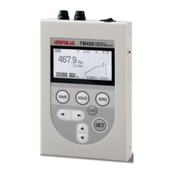
- Page 1 TM400 PORTABLE TORQUE MONITOR OPERATION MANUAL 01FEB2018REV.1.06...
- Page 2 Thank you for purchasing Portable Torque Monitor TM400 for UTMⅡ/UTMV. Read this manual and understand the contents prior to using in order to utilize the TM400 top caliber functions fully and safely. Keep this operation manual in a safe place to be used for further reference.
- Page 3 Doing so may cause failure such as faulty connection as well as electrical shock. ● Although the TM400 is considered to be sufficiently shock absorbing during delivery, reusing the same packaging materials may damage the product when a shock is encountered.
- Page 4 Product supporting RoHS Directive Product supporting RoHS Directive The parts and accessories used in this product (including the operation manual, package box and so on) support RoHS Directive, which regulates the use of toxic substances that may have adverse effects on the environment and the human body.
-
Page 5: Table Of Contents
Contents Contents Contents 1 Outline ............1 1-1. - Page 6 Contents Contents Other pulse (OTHER PUL.) (These items only available in case the Encoder pulse is set to OTHER) ..19 Unit (UNIT) ............20 Direction (DIRECTION) .
- Page 7 Contents Contents Types of displayed graphs ......... . 34 Plot mode (PLOT MODE).
-
Page 8: Outline
Package contents The following items are included in the package box. Be sure to check the contents before use. TM400 OPERATION MANUAL TM400 main unit TM400 operation manual Dedicated AC adapter ・ ・ ・ One unit ・ ・ ・ One copy ・... -
Page 9: Part Names And Functions
1 Outline 1-3. Part names and functions Chapter UTMⅡ connection connector Power switch External power input connector USB connector Connection connector for rotary encoder Charge lamp Operation key Display unit Display unit The following three kinds of information are displayed. 1) Indicated value display (numerical value) 2) Graph display 3) Hold value display Refer to P.4"1-5.Description and key operation for each screen"... -
Page 10: Screen Configuration
Connection connector for rotary encoder UTMⅡ rotary encoder is connected with the dedicated cable. External power input connector This is a jack to connect the AC adapter dedicated for the TM400. USB connector This connector is used to connect the product with a PC. -
Page 11: Description And Key Operation For Each Screen
1 Outline 1-5. Description and key operation for each screen Chapter Indicated value display screen Status display 1 Battery status Current time YY/MM/DD hh:mm:ss Indicated value (torque) Indicated value (rotation speed) Indicated value (angle) When using the rotary encoder for setting values Status display 2 Status display 1 AC adapter is in use... -
Page 12: Graph Display Screen
1 Outline Graph display screen Chapter Status display 1 Battery status Y-axis start point, scale Indicated value (torque) Indicated value (rotation speed) Indicated value (angle) When using the rotary X-axis start point, encoder for setting values scale Status display 2 Functions of operation keys Enlarge/reduce X-axis of a graph Enlarge/reduce Y-axis of a graph ▲... -
Page 13: Setting Value Display Screen
1 Outline Deleting recorded data Chapter Recorded data can be deleted by pressing the ZERO key on the hold value display screen. On the displayed confirmation screen, press the key to delete data or press the key to reset (stop) deleting. Precautions All data will be erased when data deletion is performed. - Page 14 1 Outline Setting value input screen Chapter There are following two types for setting value input. (1) Select from setting items (example: UTM capacity) Press the key on the main screen and enter the setting value display screen. Display the "CONFIG TORQUE" screen using keys.
-
Page 15: Connection
2-1. Power supply Chapter Connect the dedicated AC adapter for the TM400 to the power input connector of the main unit. Battery is built in the TM400 (available duration for continuous use: approx. five hours). Procedure to charge battery Connect the dedicated AC adapter to the external power input connector and AC outlet. -
Page 16: Rotary Encoder Connection
2 Connection ● Pin assignment Pin-out Pin number Wire color Signal name PWR+ (+24V) Black PWR- (0V) Green SIG IN (±5V DC) Chapter White SIG GND Yellow PULSE IN+ Brown PULSE IN- * The shield is not connected to the Shield Braided wire UTMⅡ... -
Page 17: Setting Procedures
3 Setting Procedures Setting Procedures 3-1. Setting configuration Main screen Chapter Indicated value Graph display Hold value display screen screen display screen TORQUE SPEED ENCODER HOLD Zero calibration Unit Encoder pulse Hold mode ZERO CAL. UNIT ENCODER HOLD MODE (P17) (P18) (P19) (P26) UTM capacity... - Page 18 3 Setting Procedures Chapter GRAPH SYSTEM Plot mode Backlight Baud rate PLOT MODE BACKLIGHT BAUDRATE (P35) (P24) (P39) Start mode Power off Data bit START MODE POWER OFF DATA BIT (P35) (P25) (P39) Start level Stop bit START LEV. STOP BIT (P35) (P23) (P39)
-
Page 19: List Of Setting Values
3 Setting Procedures 3-2. List of setting values ■Torque Default Setting Calibration Name Range value protection protection Zero calibration (ZERO CAL.) -5.000 to 5.000 [V] ◎ 0: 0.03, 1: 0.05, 2: 0.1, 3: 0.2, 4: 0.3, 5: 0.5, 6: 1, 7: 2, 8: 3, 9: 5, 10: 10, 18: 1000 11: 20, 12: 30, 13: 50, 14: 100, UTM capacity (UTM CAP.) - Page 20 3 Setting Procedures ■Encoder Default Setting Calibration Name Range value protection protection 0: NOT USE, 1: 720PULSE, 2: 1080PULSE, 3: 1440PULSE, Encoder pulse (ENCODER) 0: NOT USE 4: 1800PULSE, 5: 2000PULSE, ◎ 6: 2880PULSE, 7: 3600PULSE, 8: 4000PULSE, 9: OTHER Unit (UNIT) 0: deg 0: deg, 1: rad ◎...
- Page 21 3 Setting Procedures ■Graph Default Setting Calibration Name Range value protection protection Plot mode (PLOT MODE) 0: REPEAT 0: REPEAT, 1: SINGLE ◎ Start mode (START MODE) 0: KEY 0: KEY, 1: EDGE↑, 2: EDGE↓ ◎ Start level (START LEV.) -9999 to 9999 ◎...
- Page 22 3 Setting Procedures ■USB Default Setting Calibration Name Range value protection protection 0: 9600, 1: 19200, 2: 38400, Baud rate (BAUDRATE) 2: 38400 bps 3: 57600, 4: 115.2k, 5: 230.4k, ◎ 6: 691.2k [bps] Data bit (DATA BIT) 1: 8 bit 0: 7, 1: 8 [bit] ◎...
-
Page 23: Torque Settings
4 Torque Settings Torque Settings 4-1. Calibration "Calibration" is the operation of matching the TM400 with a sensor. Check the UTMⅡ to be used. 4-2. Calibration procedure for torque Chapter Register the rated capacity value of the sensor. UTM capacity Set the sign of the sensor. -
Page 24: Decimal Point (Decimal P.)
4 Torque Settings Decimal point (DECIMAL P.) (These items only available in case the UTM capacity is set to OTHER) Set the decimal point of torque to display. <Setting range> 0000, 000.0, 00.00, 0.000 Sign (SIGN) Set the sign of torque. <Setting range>... -
Page 25: Calibration Procedure For Rotation Speed
1, 2, 5, 10, 20, 50, 100 Quick stop mode (QUICK STOP) (optional if there is no change) This is a function to shorten the time for the rotation speed display of the TM400 to reach zero after rotation stop. -
Page 26: Calibration Procedure For The Encoder (Only When Using The Encoder)
4 Torque Settings e.g.) Rapid deceleration from 3000rpm When the quick stop mode is OFF When the quick stop mode is ON 3000rpm 3000rpm Rotation Rotation speed speed 0rpm 0rpm 3000rpm 3000rpm Display Display 0rpm 0rpm 0rpm is displayed after 1s. 0rpm is displayed after 4 cycles. -
Page 27: Unit (Unit)
4 Torque Settings Unit (UNIT) Set the unit of value to display. <Setting range> deg, rad Direction (DIRECTION) Set the rotation direction of UTMⅡ. <Setting range> NORMAL, REVERSE - NORMAL Select this option when using the UTMⅡ clockwise viewing from the drive side. -
Page 28: Recording Angle Mode (Rec.ang.md)
4 Torque Settings Recording angle mode (REC.ANG.MD) Torque value acquisition method can be selected. <Setting range> PER SAMP., PER ANG. - PER SAMP. Torque value is measured and saved synchronizing with sampling frequency. It is suitable for storing time-series data. Recording time length is fixed according to maximum recording time setting, but 100 second at max. -
Page 29: Function Setting Procedures
5 Function Setting Procedures Function Setting Procedures 5-1. Low-pass filter (LPF) This is a low-pass filter for canceling unnecessary noise contents by filtering input signals from UTMⅡ. A cut-off frequency of a low-pass filter can be selected from 10Hz to 30kHz. Frequency contents higher than the set frequencies will be attenuated. -
Page 30: One-Touch Zero
The operation stops if the key is pressed. 5-5. ID setting (ID) Sets the device ID of the TM400. Separate ID can be assigned to each device. <Setting range> 0 to 9999... -
Page 31: Calibration Protection (Cal. Prot.)/ Setting Protection (Set. Prot.)
5 Function Setting Procedures 5-6. Calibration protection (CAL. PROT.)/ setting protection (SET. PROT.) This function prohibits changes to settings to prevent setting and calibration values from being changed by operational errors. <Setting range> OFF, ON Key point Refer to P.12 "3-2.List of setting values" for setting items locked by the calibration protection and setting protection. -
Page 32: 5-11.Power Off (Power Off)
5 Function Setting Procedures 5-11. Power off (POWER OFF) When the TM400 is not operated for a fixed time, it enters into the low power consumption mode. <Setting range> 0 to 10 [MIN] Key points If the setting is set as 0 minutes, it will not enter into the low power consumption mode. -
Page 33: Hold Function
Holds the maximum value (peak value) of torque in the positive direction and the maximum value (peak value) of angle in the positive direction. Rotation speed will not be hold. Start mode (START MODE) There are two start mode settings for the TM400. <Setting range> KEY, LEVEL - Key:... -
Page 34: Start Level (Start Lev.)
6 Hold Function Start level (START LEV.) Sets the level to start detection. <Setting range> -9999 to 9999 Stop level (STOP LEVEL) Sets the level to stop detection. <Setting range> -9999 to 9999 Zero clear at the start of hold section (START CLR) Set whether or not to reset the angle to zero at the start of hold section. -
Page 35: Peak Hold
6 Hold Function 6-3. Peak hold Holds the maximum value (peak value) of torque in the positive direction. - Operation of peak hold (start mode: key) Detection/hold Hold release Hold fix section section section Torque Indicated value Time key input HOLD Lights off Flashes Lights on... -
Page 36: Bottom Hold
6 Hold Function 6-4. Bottom hold Holds the maximum value (bottom value) of torque in the negative direction. - Operation of bottom hold (start mode: key) Detection/hold Hold release section Hold fix section section Torque Indicated value Time key input HOLD Lights off Flashes Lights on... -
Page 37: Peak To Peak Hold
6 Hold Function 6-5. Peak to peak hold Holds the difference (range) between the peak and bottom values of torque. - Operation of peak to peak hold (start mode: key) Hold Hold release Detection/hold section fix section section Torque Indicated value Indicated value = 0 Standard line Time... -
Page 38: Average Hold
6 Hold Function 6-6. Average hold Holds the average value of torque. - Operation of average hold (start mode: key) Hold fix Hold release Detection/hold section section section Torque Indicated value Indicated value = 0 Time key input HOLD Lights off Flashes Lights on Lights off... -
Page 39: Peak Hold (Angle)
6 Hold Function Key points The detection section for average hold is up to 24 hours. It will automatically stop after 24 hours. 6-7. Peak hold (angle) Holds the maximum value (peak value) of torque in the positive direction and the maximum value (peak value) of angle in the positive direction. - Page 40 6 Hold Function - Operation of peak hold (angle) (start mode: level) Detection/hold Detection/hold section Hold fix section section Torque Indicated value Angle hold value Start level Stop level Angle key input HOLD Lights off Flashes Lights on Flashes Lights off HOLD display After pressing the key, hold operation starts when torque and angle exceeds the start level...
-
Page 41: Graph
7 Graph Graph The TM400 is equipped with a function to display the input data on a graph. The settings related to graph display are explained as follows. 7-1. Graph display Status display 1 Battery status Y-axis start point, scale Indicated value (torque) -
Page 42: Plot Mode (Plot Mode)
7 Graph *1: The plotting time can be changed by setting the maximum recording time of setting values as follows (thin-out): 5 seconds No thin-out 20ksps 10 seconds Take 1 data from 2 samples 10ksps 20 seconds Take 1 data from 4 samples 5ksps 40 seconds Take 1 data from 5 samples... -
Page 43: Stop Mode (Stop Mode)
7 Graph Stop mode (STOP MODE) Sets the stop mode for graph. <Setting range> CYCLE, MAX. REC. - CYCLE Use of encoder Not used: Stops plotting when the graph is plotted up to the X-axis full scale or the maximum recording time. Used: Stops plotting when the graph is plotted up to the timing of the angle to be reset to 0 (set by the setting value "zero clear") or... -
Page 44: Y-Axis Start Point (Y Start)
7 Graph Y-axis start point (Y START) Sets the start point for Y-axis of a graph. <Setting range> -9999 to 9999 Y-axis scale (Y SCALE) Sets the Y-axis scale of a graph. The Y-axis scale can also be changed on a graph display screen ( keys). -
Page 45: Usb Interface
8 USB Interface USB Interface USB interface is used to read the indicated values of the TM400 and to write the setting values into the TM400. This interface is convenient for processing such as totals and records by connecting the TM400 to a PC. Furthermore, reading and writing setting values and reading graph data are possible using a dedicated PC application. -
Page 46: Usb Interface Setting
8 USB Interface USB interface setting Set the USB I/F setting of the TM400. The I/F setting is transmission. Baud rate (BAUDRATE) <Setting range> 9600, 19200, 38400, 57600, 115.2k, 230.4k, 691.2k [bps] Data bit (DATA BIT) <Setting range> 7, 8 [bit] Stop bit (STOP BIT) <Setting range>... - Page 47 1 to 9: After sending 1 data, a specified number of data is thinned out before sending the next data. TM400 reply 0 0 0 0 0 0 1 0 0 0 0 1 CR Command received by TM400 Head 0 0 CR Chapter Sign...
- Page 48 Host * Character: ASCII O L D 0 0 Delimiter H O L D 0 0 TM400 reply Data No. (00 to 99) Command received by TM400 * 00 is the newest. YY/MM/DD hh:mm:ss 0 Delimiter Sign Sign Sign Use of encoder...
- Page 49 Host * Character: ASCII Delimiter R C + 0 0 0 0 0 Delimiter TM400 reply Sign Command received by TM400 Rotation speed - Reading rotation speed (current value) Host * Character: ASCII Delimiter R D + 0 0 0 0 0 Delimiter...
-
Page 50: Setting Value Communication Format
8 USB Interface - Reading three display values Host * Character: ASCII Delimiter R H , TM400 reply Command received by TM400 0 Delimiter Sign Sign Sign Use of encoder Torque Rotation speed Not used: --------- Used: Angle - Reading three current values... - Page 51 8 USB Interface Unit W 1 0 0 0 0 0 0 0 0 0 (No writing at Calibration LOCK) Minimum scale W 1 1 0 0 0 0 0 0 0 0 (No writing at Calibration LOCK) UTM type W 1 2 0 0 0 0 0 0 0 0 (No writing at Calibration LOCK) Moving average W 1 3 0 0 0 0 0 0...
- Page 52 Setting value (Max. 8 digits) * Only input 0 where the setting value is 0. Attention After receiving a response from the TM400, leave an interval of 5 mSec or more Chapter before sending the next command from the host.
-
Page 53: Specifications
9 Specifications Specifications 9-1. Specifications Torque input: Voltage input Signal input range -5.0 to 5.0V Input impedance: 1MΩ or over Accuracy Non-linearity: 0.02% FS ± 1 digit or less Zero drift: 0.2mV/°C RTI or less Gain drift: 0.01%/°C or less Analog filter Low-pass filter (-6dB/oct.) Select from 10, 30, 100, 300, 1k, 3k, 10k, or 30k Hz A/D converter... -
Page 54: Display Section
9 Specifications Display section Display unit 128x64 dot monochrome LCD (display area 28x57mm) Display content Numerical value display (torque, rotation speed, angle) Graph display (torque-time, torque-displacement) Status display (High, Low, OK, Hold) Status display Status display 1: A (AC adapter in use)/N (writing NOV RAM)/ B (backup battery error)/P (buffering data for pretrigger)/ R (taking graph) Status display 2:... -
Page 55: Operation
9 Specifications Operation Power switch Locker switch One piece Setting keys Membrane keys SAVE HOLD ZERO ▲ ▼ General performance Power supply Built-in rechargeable battery (lithium ion battery) Duration for continuous use: Five hours AC adapter Power consumption Approx. 7W (with AC adapter) Approx. -
Page 56: External Dimensions
9 Specifications 9-2. External dimensions Unit: mm For inguiries regarding Unipulse products, please contact us below. Chapter... -
Page 57: Block Diagram
9 Specifications 9-3. Block diagram Operation Backup battery Non-volatility memory interface +SIG Low-pass Buffer filter -SIG Power switch Power supply unit External power supply (+12V) Charging circuit Built-in rechargeable battery Chapter... -
Page 58: 10Appendices
10 Appendices Appendices 10-1. List of error displays Torque Signal input range The input electric signal substantially exceeds the signal -LOAD Over by -5V input range. This occurs also when an excessive load is applied to the sensor or when the input terminal becomes Signal input range +LOAD open circuit due to cable disconnection and so forth. -
Page 59: Initialize (Initialize)
The power cannot be turned on. Connect the dedicated AC adapter included and charge the battery. The TM400 is equipped with a function to enter into the low power consumption mode automatically if it is left without operation (power off). -
Page 60: 10-5.Conformity With Ec Directives
10 Appendices 10-5. Conformity with EC directives The TM400 Torque Monitor is a CE-marked EC-Directive-conforming product (by the Council of the European Union). - Low Voltage Directive EN62311:2008 (test distance: 10cm) - EMC Directives; EN61326-1 EN55011 EN61000-3-2 EN61000-3-3 EN61000-4-2 EN61000-4-3 EN61000-4-4...
Need help?
Do you have a question about the TM400 and is the answer not in the manual?
Questions and answers