Table of Contents
Advertisement
Advertisement
Table of Contents

Related Manuals for Unipulse F372A


Summary of Contents for Unipulse F372A
- Page 1 F372A/F377A CC-Link I/F OPERATION MANUAL 26APR2016REV.3.04 「CC-Link Ver.1.10」...
- Page 2 This document describes the standard specifications of the CC-Link I/F that links a PLC and F372A/ F377A. By using the CC-Link I/F, the F372A/F377A can be controlled directly from the PLC, so that wiring can be substantially reduced. Readers this document should have basic knowledge of the programming of the PLC and basic knowledge of the CC-Link I/F.
-
Page 3: Table Of Contents
■ RY (PLC → F372A/F377A) signal ........ -
Page 4: Appearance Descriptions
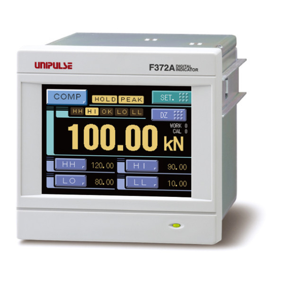
1.Appearance Descriptions Appearance Descriptions ■F372A/F377A with CC-Link I/F Name of Each Part ■CC-Link I/F Status LED Displays the status of communication. Status LED (Refer to "Status LED" on Page3.) Communication connector Connector for CC-Link interface. Communication connector (Refer to "Communication Connector" on Page2.) -
Page 5: Communication Connector
4.Communication Connector Measurement work selection: Select the method of specifying measurement work. Control input selection: Select the method of specifying control (SECTION signal, T/H signal, GRAPH TRIG signal) input. Setting range: Communication Specifying by external input is disabled, and specifying by CC-Link is enabled. External input Specifying by CC-Link is disabled, and specifying by external input is enabled. -
Page 6: Status Led
F372A/F377A enables to change the numbers of occupied stations by its setting. Be careful the assignment of station number, double used station number is not available for PLC. The address of remote (F372A/F377A) will be changed in accordance with the assignment of station number. -
Page 7: Address Map
7.Address Map Address Map ■Data domain: Remote resister M→R (PLC→F372A/F377A) M: Master, R: Remote When occupied 4 stations Content Device Buffer Station Address M → R 01E0H RWw0000 32bit 01E1H RWw0001 01E2H RWw0002 32bit 01E3H RWw0003 01E4H RWw0004 32bit 01E5H... -
Page 8: Explanation For Remote Resister M → R
7.Address Map ■Explanation for remote resister M → R ◎Exclusive area (32bit BCD) Use for writing into each set value by using request flag 1. 4bit 4bit 4bit 4bit Sign 4bit 4bit 4bit 4bit Set HH, HI, LO, LL and Near zero. If each digit is set the value of which is larger than 9, it is handled by setting it as 9 is set. -
Page 9: Data Domain: Remote Resister R→M (F372A/F377A→Plc)
7.Address Map ■Data domain: Remote resister R→M (F372A/F377A→PLC) M: Master, R: Remote When occupied 4 stations Content Device Buffer Station Address R → M 02E0H RWr0000 Hold value 1 32bit 02E1H RWr0001 02E2H RWr0002 Real time value 32bit 02E3H RWr0003... -
Page 10: Explanation For Remote Resister R → M
7.Address Map ■Explanation for remote resister R → M ◎Hold value 1/ Hold value 2/ Hold value 3 (32bit BCD) The indicated value is stored. 4bit 4bit 4bit 4bit Sign Decimal place 4bit 4bit 4bit 4bit Decimal place is indicated as follows. 0: None 1: 0.0 2: 0.00 3: 0.000 4: 0.0000 Sign is indicated as follows. - Page 11 7.Address Map ◎Indicated value (select) (32bit BCD) The data of the indicated value (select) changes according to hold value select 0, hold value select 1, and real time value select. 4bit 4bit 4bit 4bit Sign Decimal place 4bit 4bit 4bit 4bit Decimal place is indicated as follows.
-
Page 12: Relay Domain
7.Address Map ■Relay domain ●Remoto output (PLC→F372A/F377A) When occupied 4 stations Remote Buffer Station Content Class address output RY0000 Request flag1 RY0001 RY0002 Request flag2 Communication RY0003 Used for Communication RY0004 with Host RY0005 RY0006 RY0007 0160H RY0008 Measurement WORK0... - Page 13 7.Address Map When occupied 2 stations Remote Buffer Station Content Class address output RY0000 Request flag1 RY0001 RY0002 Request flag2 Communication RY0003 Used for Communication RY0004 with Host RY0005 RY0006 RY0007 0160H RY0008 Measurement WORK0 RY0009 Measurement WORK1 RY000A Measurement WORK2 RY000B Measurement WORK3 RY000C...
- Page 14 7.Address Map When occupied 1 station Remote Buffer Station Content Class address output RY0000 RY0001 D/Z reset RY0002 RY0003 SECTION RY0004 GRAPH TRIG RY0005 Display select (Comparison) RY0006 Display select (Hold) RY0007 Display select (Graph) 0160H RY0008 Measurement WORK0 RY0009 Measurement WORK1 RY000A Measurement WORK2...
- Page 15 7.Address Map ●Remote input (F372A/F377A→PLC) When occupied 4 stations Remote Buffer Station Content Class address output RX0000 Request flag 1 response RX0001 RX0002 Request flag 2 response Communication RX0003 R/W response Used for Communication RX0004 with Host RX0005 RX0006 CPU normal operation...
- Page 16 7.Address Map When occupied 2 stations Remote Buffer Station Content Class address output RX0000 Request flag 1 response RX0001 RX0002 Request flag 2 response Communication RX0003 R/W response Used for Communication RX0004 with Host RX0005 RX0006 CPU normal operation RX0007 00E0H RX0008 Measurement WORK 0 response...
- Page 17 7.Address Map When occupied 1 station Remote Buffer Station Content Class address output RX0000 RX0001 RX0002 RX0003 RX0004 RX0005 RX0006 CPU normal operation RX0007 00E0H RX0008 Measurement WORK 0 response RX0009 Measurement WORK 1 response RX000A Measurement WORK 2 response RX000B Measurement WORK 3 response RX000C...
-
Page 18: Ry (Plc→F372A/F377A) Signal
GRAPH TRIG Start graph plotting, and Stop. (Refer to main operation manual.) Print command Print out to the Unipulse printer connected with SI/F by ON edge. Display select (Comparison) Operate changing to Comparison Screen by ON edge. Display select (Hold) Operate changing to Hold Screen by ON edge. -
Page 19: Rx (F372A/F377A→Plc) Signal
The signal is reversed between ON and OFF at approx. 1 second interval in Normal CPU normal operation operation. Measurement WORK comparing by F372A/F377A is indicated. (4bit: 0 to 15) WORK0 to 3 response Decimal place 0 to 2 Decimal place is indicated. (3bit: 0 to 4) ON signal output according to comparison condition of HH. -
Page 20: Setting Procedure
8.Setting Procedure Setting Procedure ■Set value writing in the exclusive data area (using request flag 1) Request flag 1 is used when Setting value is written in. The Setting value is written in at Request flag ON edge when Request flag 1, 2 and Request flag response 1, 2 are OFF. RWw0000 to RWw0009 when 4 stations occupied and RWw0000 to RWw0003 when 2 stations occupied become Exclusive data area. -
Page 21: Set Value Reading In The General-Purpose Data Area (Using Request Flag 2)
8.Setting Procedure ex.) When 4 stations occupied (writing in Setting value) Request flag 2 (RY0002) Request flag 2 response (RX0002) (RY0003) General purpose data area (RWw000C) (RWw000D) WORK No. (RWw000F) Command No. (RWw000E) R/W response (RX0003) Command No. response (RWr000E) (The Upper row of signal level is ON. -
Page 22: Sample Of Ladder Program
Sequence completion 0 to 121 row Initial setting for Communication speed 96 row Remote device F372A/F377A occupies 4 stations of PLC start from station 1. 125 row RX PLC read value from F372A/F377A 135 row RWr PLC read value from F372A/F377A... - Page 23 M9038 [SET 1 cycle ON [PLS [SET [SET * Up to here Initial setting for communication *< RX PLC read value from F372A/F377A > M9036 [FROM H0E0 D200 ON at all times *< RWr PLC read value from F372A/F377A >...
- Page 24 8.Setting Procedure * Writting in HH ( M100 ) *< R/W relay OFF > M200 M9038 M100 [WAND H0FFF7 D208 Request 1 cycle ON [MOV D300 D244 flag 2 response [MOV D301 D245 *< HH command > [MOV D246 *< WORK No. >...
-
Page 25: Alarm Codes
9.Alarm Codes * (M104) M200 M9038 M104 [MOV D228 D302 Request 1 cycle ON D229 D303 [MOV flag 2 response When Reguest flag 2 response turns ON *< > Reguest flag 2 goes OFF. [WAND H0FFFB D208 H160 D208 *< To M105 >... -
Page 26: Unit Setting List
10.Unit Setting List Unit Setting List * Numbers are values of input range. Also, “0” results in no unit. Weight Force Pressure Other μg μN μPa kg/h kg/s g/cm kg/m /min μNm g/ml dyne mg/m l/min kdyne μbar kg/m mbar kgm/s %... -
Page 27: Command List
11.Command List Command List Command Classification of items Item Setting range HI Limit / HI-A Limit 0 1 0 1 -99999 to 99999 Work Setting WORK0 to 15 LO Limit / LO-A Limit 0 1 0 2 -99999 to 99999 HH Limit / HI-B Limit 0 1 0 3 -99999 to 99999... - Page 28 11.Command List Command Classification of items Item Setting range Calibration Excitation Voltage 2 0 0 1 0: 2.5V, 1: 10V Setting Zero Calibration 2 0 0 2 -3.000 to 3.000mV/V F372 CAL0 to 3 Equivalent Input Calibration 2 0 0 3 -3.000 to 3.000mV/V (Excluding 0.) Analog Input Selection 2 0 0 1...
- Page 29 11.Command List Command Classification of items Item Setting range Before Value Comparison 3 0 0 1 0: OFF, 1: ON Expansion Expansion Setting Comparison Setting Relative Value Comparison 3 0 0 2 0: OFF, 1: ON Expansion Double Hold 3 1 0 1 0: OFF, 1: ON Hold Setting Auto Reset Select...
- Page 30 11.Command List F370•F371•F372•F377 common command Command Classification of items Item Setting range HH Limit 0 0 1 1 -99999 to 99999 Work Setting WORK0 to 15 HI Limit 0 0 1 2 -99999 to 99999 LO Limit 0 0 1 3 -99999 to 99999 Comparison Setting...
Need help?
Do you have a question about the F372A and is the answer not in the manual?
Questions and answers