Advertisement
UTMⅡ-20Nm/UTMⅡ-20Nm (K)
1. Outline of the product
This product is a torque meter that detects the torque applied to a rotating shaft with a strain gauge, transmits
it to the receiving section by non-contact, and outputs it as voltage.
By simply giving 24V DC power without adjustment, voltage calibrated by the rated torque is output. Also,
since an open collector output for rotation detection is equipped, the rotation speed and torque can be
measured at the same time.
2. Warnings, prohibitions, and cautions for handling
This sign indicates don'ts (prohibited matters)
PROHIBITION
on operation
Do not disassemble this product.
Do not drop this product or give it a high impact.
Do not use this product for other purposes than torque measurement.
This sign forewarns the presence of hazards that could result in
WARNING
serious injury or fatality when incorrectly handled.
Warning on design
Warning on wiring
●For the entire system to function safely when
●Do not connect commercial power directly to
this product becomes faulty or malfunctions,
this product.
provide a safety circuit outside this product.
●Before performing the following, make sure that
●Before using this product as described below,
no power is applied.
make sure to consult with our sales personnel.
• Insertion/extraction of connectors
• Use in environments not described in the
• Wiring/connection of cables
operation manual.
●Insulate the ends of unused cables to prevent
• Use greatly impacting human lives and assets,
their contact with other metallic parts and
such as medical devices, transport devices,
electrically charged parts.
weapons, entertainment devices, and safety
● Before applying power, carefully check the
wiring, etc.
devices.
●Touching this product while in operation with
Warning during startup and maintenance
your hands or fingers will cause injury. Also,
●Do not repair, internally inspect, or modify this
your clothing may get caught. For hazard
product. A fire or electric shock may occur.
prevention, make sure to install a safety cover,
Please ask us for repair.
or provide a safety device so that the equipment
●Make sure that the fastened parts are reliably
is stopped if there is a danger of touching the
secured before startup.
rotating parts.
Warning during operation
●If this product is damaged, the drive side and
load side may be completely separated. For
●Use the power supply voltage and load within
hazard prevention, make sure to provide a
the specification and rated ranges. Use beyond
safety mechanism, such as a safety brake.
the rating may not only damage this product but
also affect the equipment to which this product
Warning on installation
has been installed.
●Do not install in the following environments.
●If the cover of the main body is opened, you
• In a corrosive or flammable gas atmospheres.
may receive an electric shock internally or get
• Where the product may be splashed with
caught in the rotating parts.
water, oil or chemicals.
●If smoke, fire, or abnormal odor is detected,
●If couplings, etc., are assembled with the shafts
immediately turn off the power.
misaligned
or
bent,
not
only
will
the
●During rotation, do not touch the rotating parts
performance of the product be unsatisfactory
of this product and also the non-rotating parts.
but also this product may be damaged by
Be careful not to get your hands, fingers, and
rotational vibrations and scattering in the worst
clothing caught in them.
case, which is very dangerous. Make sure that
● Operation exceeding the maximum rotation speed
a balance is achieved and there is no vibration
will increase vibration, and may damage and
under low-speed rotation before operation, in
scatter the product in the worst case, which is
addition to shaft centering as a matter of
very dangerous. Make sure to use at the
course.
maximum rotation speed or less. Also, even at the
●Install this product to your equipment within the
maximum rotation speed or less, please use it so
allowable installation errors. Use with the
that vibration by the dimensional errors on
allowable installation errors exceeded may
attachment does not take place.
damage the product or affect the equipment to
●Operation with the fastened parts loose may
which this product has been installed.
cause a slip, generating abnormal heat, or
●Do not pass current through the shafts or
cause damage, affecting the equipment to
housing of this product. Also, take external
which this product has been installed. Make
measures to prevent leakage current from
sure to use with the fastened parts reliably
flowing through the shafts.
secured.
ROTATING TORQUE METER OPERATION MANUAL
This sign forewarns the presence of hazards that could result in
CAUTION
personnel injury or property damage when incorrectly handled.
Caution on installation
Caution on wiring
● Do not install in the following environments.
● Depending on routing, cables may be charged
• Where the temperature/humidity exceeds the
with static electricity. The charged static electricity
range of the specifications.
may
destroy
• Where the temperature changes remarkably or
equipment.
● Use stable 24V DC power.
there is a danger of freezing or condensing.
● Use shielded cables.
• Where there is a temperature difference
● For cable extension, AWG26(0.13mm
between the drive side and load side.
and a length of maximum 10m or less should be
• Outdoors
observed.
• Places exposed to direct sunlight
• Dusty places
Caution during startup and maintenance
• Poorly-ventilated places
● If not used by the specified method, the protection
• Places with a high salt content and a lot of
performance of this product may be impaired.
metallic powder.
● Maintenance
• Where the main body is directly affected by
• When performing maintenance, disconnect the
vibrations or shocks.
power.
● Take sufficient shielding measures including
• Do not wipe with a wet rag. In the case of heavy
cables for use in the following places.
contamination, wipe off the contamination with
• Near power lines
a cloth after dipping it into a diluted neutral
• Where a strong electric field or a strong
detergent and wringing it well, and then wipe
magnetic field is generated
with a soft, dry cloth.
• Where static electricity, relay noise or the like is
Caution during transportation
generated.
● When this product is shipped, spacers made of
● Install this product as far away from devices
corrugated cardboard are used as cushioning
generating high frequency, high voltage, large
materials. Though it is factory-designed so that
current, surge, etc., as possible. Also, carry out
shocks can sufficiently be absorbed, breakage
wiring separately from their power lines. Do not
may result if shocks are applied when the spacers
carry out parallel wiring and common wiring.
are reused for transportation. If you send this
● Do not use it, broken down.
product to us for repair, etc., take adequate
● Do not use screws other than specified by us.
measures against shocks by using polyurethane
materials, etc., separately.
Caution during disposal
● If you dispose of the product, handle it as
industrial waste.
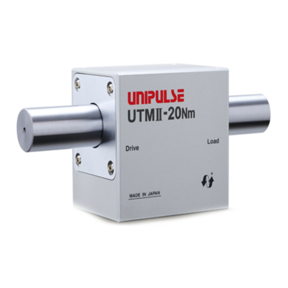
3. Part names and functions
② Rotating shaft
④ Housing
on the load side
① Rotating shaft
on the drive side
③ Direction of rotation
① Rotating shaft on the drive side
This is a drive side rotating shaft. A drive unit that rotates the
shaft is connected to it.
② Rotating shaft on the load side
This is a measuring side rotating shaft. It is connected with the
drive side rotating shaft internally. The object to measure the
torque is connected to it.
③ Direction of rotation
A positive output is made by turning the load
sidecounterclockwise when viewed from the drive side.
④ Housing
This is the main body of the measuring instrument. It is connected
by shafts and bearings. For the housing detent fixing holes, use
M3 screws 6mm or less in length.
⑤ Connector
Connect power and signal wires.
Connector used: HR30-6R-6S(71) Hirose Electric
Compatible plug: HR30-6P-6P(71) Hirose Electric
Connector pin assignments
Pin
Type
No.
1
Power
the
semiconductors
in
the
supply
2
2
) or more
3
Torque
signal
4
5
Rotation
signal
6
⑥Attached cable (2m)
Waterproof connector (plug)
⑤ Connector
HR30-6P-6P (71)
(HR30-6R-6S(71))
⑥ Attached cable
Connector pin assignments
Pin arrangement
04DEC2013REV.1.01
Signal name
Description of signal
Connect to +24V power supply. Voltage range must be
within +24V plus-minus 15%. Use a power supply that can
PWR+(+24V)
stably operate with a small load since the consumption
current is 150mA or less.
PWR + (+ 24V)
PWR-(0V)
PWR - (0V)
This is a torque signal output. As for voltage output, 0V is
output at no load, and 5V is output when the rated torque is
applied. The minimum drivable load is 2kΩ.
R
SIG OUT
(±5V DC)
680Ω
SIG OUT (±5VDC)
SIG GND
Depending on the environment where the product is used,
noise from motor or inverter and signal from the product
may overlap. To reduce the noise level, please use RC
circuit/filter to let signal output pass through the filter right
before input device.
SIG GND
R
SIG OUT
(±5VDC)
Connection
UTMⅡ
C
device
SIG GND
R=100Ω
C=0.1μF
Pulse signal output generates 4 pulses per 1 rotation.
Rated voltage and current are 30V and 10mA, respectively.
PULSE OUT+
(Photocoupler)
PULSE OUT +
PULSE OUT-
PULSE OUT -
1 : Red
PWR + (+ 24V)
2 : Black
PWR - (0V)
3 : Green
SIG OUT (±5VDC)
4 : White
SIG GND
5 : Yellow
PULSE OUT +
6 : Brown
PULSE OUT -
Shield
50mm
2000mm
Pin No.
Cable color
Signal name
1
Red
PWR+(+24V)
2
Black
PWR-(0V)
3
Green
SIG OUT(±5VDC)
4
White
SIG GND
5
Yellow
PULSE OUT+
6
Brown
PULSE OUT-
*The shield is not connected
Shield
Braided wire
to the UTMⅡ housing.
Advertisement
Table of Contents

Related Manuals for Unipulse UTM II-20Nm


Summary of Contents for Unipulse UTM II-20Nm
- Page 1 UTMⅡ-20Nm/UTMⅡ-20Nm (K) ROTATING TORQUE METER OPERATION MANUAL 04DEC2013REV.1.01 1. Outline of the product Connector pin assignments This sign forewarns the presence of hazards that could result in CAUTION This product is a torque meter that detects the torque applied to a rotating shaft with a strain gauge, transmits Type Signal name Description of signal...
- Page 2 We offer optimum peripherals, such as couplings, according to your application/use. Please feel free to Model Supported couplings contact us. UCM44 UCM56 UTM Ⅱ-20Nm/UTMⅡ-20Nm(K) Unipulse Corporation UCM65 9-11 Nihonbashi Hisamatsucho, Chuo-ku, Tokyo 103-0005 For details, please contact our sales personnel. Tel. +81-3-3639-6120 Fax: +81-3-3639-6130...
Need help?
Do you have a question about the UTM II-20Nm and is the answer not in the manual?
Questions and answers