Advertisement
Quick Links
USH
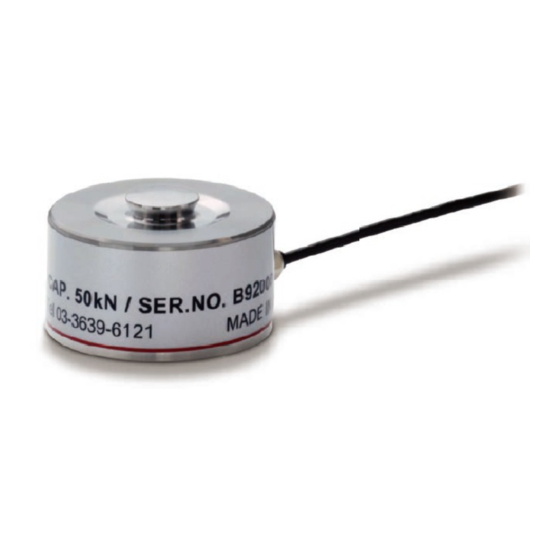
COMPACT HIGH-CAPACITY COMPRESSION TYPE LOADCELL
1.Product outline
USH series are compact compression type loadcells with high-capacity.
There are suitable for built-in applications.
2.Handling prohibitions and precautions
Prohibited actions while operating the product
Prohibitions
(Prohibited actions)
Do not disassemble this product.
Avoid dropping or giving a shock to the product.
Precautions
Events that may cause injury to personnel or material damage
in case of misuse.
● Provide sufficient strength to the installation location.
● Do not install the product in the following environments:
- In an atmosphere with corrosive or combustible gases;
● Perform adequate isolation if the product is used in the
- Locations where temperature or humidity exceeds
following locations:
specifications;
- Locations subject to noise such as static electricity;
- Locations subject to drastic temperature fluctuations or
- Locations subject to strong electric field and intense
icing and condensation;
magnetic field.
- Locations exposed to direct sunlight;
● Perform electric welding before mounting the loadcell.
- Locations subject to direct vibration or shock
Take caution not to make current flow in the loadcell if
● Consult us if this product is to be used under a special
the welding needs to be performed after mounting.
environment.
● Handle this product as industrial waste when disposing.
3.Installation procedure
(1) For loadcell mounting, be sure to use proper screws by the specifications. Screw insertion length should
be around 1.5times longer than diameter of a screw. Screws must be tightened at instructed torque. Use
screw locking adhesive if needed.
Recommended tightening torque.....M2: 0.32 N·m, M4: 2.7 N·m
(2) The base plate must be made of steel having enough rigidity. Also its flatness should be 0.01mm or less
and surface roughness should be less than Ra3.2.
(3) The load plate must be made of steel having enough rigidity and hardness. Also its flatness should be
0.01mm or less, surface roughness should be less than Ra3.2, and hardness should be more than HRC50.
The loadcell characteristics may be changed with the flatness of the base.
Load direction
There is a hollow at the
bottom of load cell.
Bolt
For installation, make sure
no load is applied on that area.
4.Wiring color of loadcell cables
Signal name / wiring color
Core wire
+EXC
+S
-S
-EXC
Six wires
Red
Yellow
Orange
Black
5.Indicator connection
Check the signal name and wiring color before connection.
(1) The cable of USH loadcell has 6 bare wire ends. Therefore USH should be used with an indicator that
accepts 6-wire input. In case USH is used with a 4-wire input indicator, both +EXC and +S wires must be
inserted to +EXC terminal of an indicator, also both -EXC and -S wires must be inserted to -EXC
terminal of an indicator. In this case, sensitivity may change a little.
Please connect SHIELD wire to SHIELD terminal of indicator.
Since load cell main body is insulated from SHIELD cable, make sure main body and indicator ground
point is connected in single-point grounding.
(2) Apply the recommended voltage for the excitation. If the applied voltage exceeds the maximum
excitation voltage, USH may get permanent damage.
(3) To extend loadcell cable, make sure to use a cable with the same diameter or bigger diameter than
standard cable. A voltage drop may occur when small diameter cable (having high resistance) is used,
and it may affect the result of measurement.
Re-calibration with an standard weight could be needed if USH is used with a 4-wire input indicator.
Please consult our sales representative for cable extension.
■Six-wire type loadcell → Six-wire type indicator
IN
OUT
OUT
IN
* SHIELD wire is not connected to load cell main body.
6.Calibration
If calibration is needed, do it on indicator. For more information, refer to the manual of indicator.
■Actual load calibration
In this calibration method, actual load is applied to a loadcell, and the value of the actual load is input using
the keys. Accurate calibration with minimal error can be performed.
Prepare a reference item such as a weight in advance.
■Equivalent input calibration
In this calibration method, only the rated output value and the rated capacity value of the loadcell are input
using the keys. This method does not involve actual load.
The values are stated on the attached data sheet upon the purchase of loadcell.
7.Trouble shooting
Determine whether the error is occurring on the loadcell side or the indicator side.
Check the damage of USH in the following ways.
(1) In case a load is applied larger than safe overload or a load in unexpected direction is applied to the USH,
make sure to check if it didn't get damaged after recalibration.
(2) When the reading on indicator is unstable or odd, do an inspection as follows after checking wiring and
precautions.
① Check the input resistance of loadcell under no-load condition. (between +EXC and -EXC)
IN
OUT
Load plate
Loadcell
IN
② Check the output resistance of loadcell under no-load condition.(between +SIG and -SIG)
Base plate
IN
OUT
IN
+SIG
-SIG
SHIELD
③ Check the signal output of loadcell (Zero-balance) under no-load condition
Green
White
Blue
IN
OUT
IN
In case measured values above are out-of-specification, please consult us.
If no problem found on USH, check the indicator in the following ways.
(1) Disconnect the USH from indicator. Check if the reading on indicator is near 0, while short the input
terminals(+SIG and -SIG).
(2) Measure the voltage of the output terminals(+EXC and -EXC) of indicator, and verify if the excitation
voltage is applied properly.
For more information, refer to the manual of indicator.
OPERATION MANUAL
■Six-wire type loadcell → Four-wire type indicator
Loadcell side
Indicator side
IN
+EXC
+EXC
+EXC
+S
+S
+S
−S
−S
−S
−EXC
−EXC
−EXC
OUT
OUT
+SIG
+SIG
+SIG
−SIG
−SIG
−SIG
SHIELD
SHIELD
SHIELD
IN
EXC
Disconnect the USH from the
S
indicator. And verify if the input
S
EXC
resistance of loadcell (between +EXC
OUT
SIG
SIG
and -EXC) is within the specification
SHIELD
range under no-load condition.
EXC
Disconnect the USH from the
S
indicator. And verify if the output
S
EXC
resistance of loadcell (between +SIG
OUT
SIG
SIG
and -SIG) is within the specification
SHIELD
range under no-load condition.
EXC
EXC
Connect the USH with an indicator.
S
S
S
S
And measure the output voltage
EXC
EXC
(Vout[mV/V]) under no-load
OUT
SIG
SIG
SIG
condition, while an excitation
SIG
SHIELD
voltage (Vin[V]) is applied. Verify if
the signal output of loadcell
Vout
(
[mV/V]) is within the
Vin
specification range. (Zero-balance)
01AUG2020REV.1.06
8.External dimension
Loadcell side
Indicator side
■USH-10KN, USH-20KN
+EXC
−EXC
+SIG
Load direction
SR40
−SIG
8
SHIELD
26
3-M2 Depth 3
P.C.D.22.75
9.Specifications
Model
Rated capacity
Rated output
Safe overload
Zero balance
Non-linearity
Hysteresis
Repeatability
Compensated temperature range
Safe temperature range
Temperature effect on zero
Temperature effect on span
Input resistance
Output resistance
Recommended excitation voltage
Maximum excitation voltage
Insulation resistance (DC50V)
Cable
Deflection at rated capacity
Natural frequency
Loadcell material
Weight
Unipulse Corporation
International Sales Department
9-11 Nihonbashi Hisamatsu-cho, Chuo-ku, Tokyo 103-0005
Tel: +81-3-3639-6120 Fax: +81-3-3639-6130
■USH-50KN
Load direction
SR60
13
40
P.C.D.32
2.5 6-conductor
2.5 6-conductor
flexible cable (3m)
flexible cable (3m)
Cable end: 7 wires
Cable end: 7 wires
3-M4 Depth 6
USH-10KN
USH-20KN
USH-50KN
10
20
50
kN
1±20%
mV/V
200
%R.C.
±20
%R.O.
0.2
%R.O.
0.15
%R.O.
0.1
%R.O.
-10 to +70
℃
-30 to +85
℃
0.2
%R.O./10℃
0.2
%R.O./10℃
Approx. 1000
Ω
Approx. 1000
Ω
5
V
7.5
V
1000 or more
MΩ
φ2.5 6-conductor flexible cable (3m)
Cable end: 7 wires
0.06
0.07
mm
20
15
kHz
Stainless steel
0.1
0.18
kg
Advertisement


Need help?
Do you have a question about the USH-10KN and is the answer not in the manual?
Questions and answers