Table of Contents
Advertisement
Advertisement
Table of Contents

Subscribe to Our Youtube Channel
Related Manuals for Unipulse F325


Summary of Contents for Unipulse F325
- Page 1 F325 DIGITAL INDICATOR OPERATION MANUAL 01JUN2015REV.1.01...
- Page 2 Be sure to read this operation manual before use in order to take full advantage of the superb quality of the F325 and to use it properly and safely. Use this indicator with accurate understanding of the contents. Keep this operation manual in a safe place to be used for further reference.
- Page 3 ● Prepare a safety circuit outside the F325 so that the entire system functions safely if the F325 fails or malfunctions. ● Be sure to contact our sales representative before use if the F325 will be used as follows: - if the indicator is used in an environment not described in the operation manual;...
- Page 4 ● Be sure to have a time interval of five seconds or longer between turning power on and off. ● Use after warming up for 30 minutes or longer following the startup of power supply. ● Protective performance of the F325 may be lost if it is not used as specified. ● Care - Unplug the power supply during maintenance.
- Page 5 *2: Radiated only for DC spec. Key points Only for DC spec., the combination of the main unit of the F325 and a lightning surge protector conforms to EN61000-4-5 (lightning surge immunity) in the EMC Directives. Refer to P.23 “ ◇Lightning surge protector connection” for information regarding light- ning surge protector connection.
- Page 6 Products supporting RoHS directive Products supporting RoHS directive Products supporting RoHS directive The parts and accessories used in this machine (including the operation manual, package box and so on) support RoHS Directive, which regulates the use of toxic substances that may have adverse effects on the environment and human body.
-
Page 7: Table Of Contents
Contents Contents Contents 1 Outline ............1 1-1. - Page 8 Contents Contents 4-6. Decimal place setting (Omit if there is no change.) ......32 ■ Decimal place setting method ........32 4-7.
- Page 9 Contents Contents 6-5. Alarm HI limit, Alarm LO limit ......... . . 50 ■...
- Page 10 Contents Contents 9-10.Interface ............73 9-11.Option type .
- Page 11 15-3.F325 block diagram ........
-
Page 12: Outline
The following items are included in the package box. Be sure to check the contents before use. F325 F325 main unit F325 operation manual F325 AC input cord* --- One unit --- One copy --- One piece Terminator Connector for BCD output... -
Page 13: Connection With Other Devices
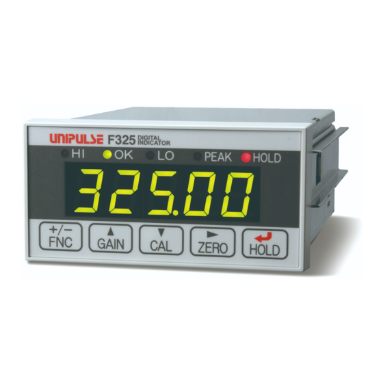
(2) Number display unit (3) Setting keys (1) Status display unit Status of the F325 is displayed. Setting items are displayed when setting is performed. Lighted: HI limit output condition is met Flashes: HH limit output condition is met * Flash is prioritized. - Page 14 1 Outline Lighted: LO limit output condition is met Flashes: LL limit output condition is met Chapter * Flash is prioritized. * LO limit output condition and LL limit output condition are subject to change depending on setting values of HI/LO limit comparison mode and hysteresis. PEAK Flashes when peak hold function is detectable.
- Page 15 1 Outline <When indicated values are displayed> Equivalent input calibration mode is on. Chapter <When setting is performed> This key selects set items and decreases one value of the flashing digit of a setting value. <When indicated values are displayed> Zero calibration mode is on (when calibration LOCK is OFF). ZERO Indicated value is forced to be zero by digital zero (when calibration LOCK is ON).
-
Page 16: Rear Panel
1 Outline ■Rear panel Chapter (2) Options space (1) Protective (4) Signal I/O grounding terminal block (3) AC power terminal block (1) Protective grounding This is a protective grounding terminal block. Be sure to ground a protective grounding terminal in order to prevent electric shock and trouble arising from static electricity. (A case and protective grounding terminal are in continuity.) Do not use screws other than the ones (with bind M4x8-tooth captive washer) for installing the main unit. - Page 17 1 Outline (4) Signal I/O terminal block Chapter This terminal block is used for inputting/outputting control signals and for inputting strain gauge type sensor signals. - Terminal block assignment OUT1 OUT2 HOLD H.RESET COM CONTROL OUTPUT CONTROL INPUT * COMs of input and output are independent. SHIELD +EXC -SIG -EXC...
- Page 18 1 Outline *1 Refer to P.45 “6-2.HI limit / LO limit / HH limit / LL limit”and P.47 “6-3.HI/LO limit comparison mode” for each signal. Chapter *2 Refer to P.44 “6-1.Output selection” for output selection. CONTROL INPUT This input terminal is used for control. This input terminal is used for controlling digital zero.
-
Page 19: Operating Procedures
SI/F (specified at the time of order, SIF). RS-485 This serial interface is used for retrieving indicated values and status of the F325 with protocols such as Modbus-RTU and UNI-Format and for writing settings into the F325. Connect B+ of the counterpart device to be connected. -
Page 20: Installation & Connection
2 Installation & Connection Installation & Connection The following are precautions related to connection to the signal I/O terminal block. Chapter The precautions described in this text are important contents regarding safety. Connect this indicator with accurate understanding of the contents. Warning ●... -
Page 21: Installation To Panel
2 Installation & Connection 2-1. Installation to panel Use the following procedures when installing the F325 to the control panel. Create holes on the panel in accordance with the panel cutout size. Chapter Panel cutout size [Unit: mm] 92(W)× 45(H)(mm) Installation panel thickness 1.6 to 3.2(mm) -
Page 22: Connection To The Signal I/O Terminal Block
If difficult to remove, make a space between the main unit and terminal block using a flathead screwdriver and try removing it again. * Straight type terminal block (CN82) is also available from UNIPULSE. Contact our sales department for details. -
Page 23: Connection Of Strain Gauge Type Sensors
-SIG -EXC +SIG Inputs of strain gauge type sensors ◇Four-wire sensor +EXC -SIG +OUT -OUT F325 -EXC +SIG SHIELD ◇Six-wire sensor Short-circuit +EXC and +S, and -EXC and -S, respectively, if connecting six-wire strain gauge type sensors. +EXC -SIG +OUT... -
Page 24: Connection Of Analog Monitor Output (Vol Out)
Connection of analog monitor output (VOL OUT) A voltage proportional to sensor inputs is output. The voltage to be output is Chapter approx. 2V per 1mV/V of sensor input. VOL OUT F325 ← Inside Outside → + External device Input resistance -... -
Page 25: Connection Of Rs-485 (Rs-485 Or Si/F Standard: Not Specified At The Time Of Order)
- SG terminal (B10 terminal) is a ground terminal (which protects a circuit) used on the circuit. SG terminal is not normally required to use if the main unit of the F325 and connection counterpart device are class D grounded. -
Page 26: F Connection (Rs-485 Or Si/F Specified At The Time Of Order: Sif)
30m. In case two-core shield twisted pair wires are used, transmission distance is approx. 300m. Do not parallel AC lines and high-pressure lines. This causes malfunction. F325 SI/F ← Inside Outside →... -
Page 27: External Output Connection
The capacity of PhotoMOS relay output is 100mA, and the withstanding voltage is up to 30V. Plus common connection and minus common connection are possible. Chapter Plus common connection <Equivalent circuit> Relay Spark killer Inside F325 Vext Output common DC power supply Load Relay... -
Page 28: External Input Connection
2 Installation & Connection Caution ● Prepare an external power supply for the relay drive (vext). ● When activating AC power supply, be sure to connect it to the F325 via relay and Chapter so on, but not directly. ● Power supply must be within the rating (DC spec.: 30V 100mA). - Page 29 2 Installation & Connection DC-input type (DCI) - Plus common connection When connecting relays, switches and so on F325 Plus common connection Push Toggle Relay Chapter switch switch contact Input A7 to A9 Ic=approx. 10mA Input 12 to 24V common + -...
-
Page 30: Power Input Terminal Connection
2 Installation & Connection Caution ● An external element must be an element in which Ic=20mA or more can be applied. ● External element leak must be 400μA or below. Chapter ● ON: DC9V or above, OFF: DC3V or below 2-9. Power input terminal connection ■AC spec. - Page 31 AC cable if the indicator is used at a voltage higher than the rating or is used overseas. ● The F325 has no power switch. Make sure to install a breaker and so on as needed. ● Be sure to ground a protective grounding terminal in order to prevent electric shock and trouble arising from static electricity.
-
Page 32: Dc Spec. (Specified At The Time Of Order)
2 Installation & Connection ■DC spec. (specified at the time of order) DC power supply may be used on the F325 if specified at the time of ordering. DC power cord is connected. Input voltage is DC12V to 24V between F325 terminals. - Page 33 Chapter Never connect AC power supply. This may cause failure. ● The F325 has no power switch. Make sure to install a breaker and so on as needed. ● Be sure to ground a protective grounding terminal in order to prevent electric shock and trouble arising from static electricity.
- Page 34 For DC spec. only, install a lightning surge protector to guard from lightning surges as necessary. The combination of the main unit of the F325 and a lightning surge protector conforms to EN61000-4-5 (lightning surge immunity) in the EMC Directives.
-
Page 35: Setting Procedure
3 Setting Procedure Setting Procedure 3-1. Setting mode configuration Indicated value display + - + - Chapter Setting mode 1 Setting mode 2 Setting mode 3 Setting mode 4 ZERO ZERO ZERO ZERO GAIN GAIN GAIN GAIN Moving average RS-485 HI limit Set value LOCK filter I/F setting... - Page 36 3 Setting Procedure Chapter Setting mode 5 Setting mode 6 Setting mode 7 ZERO ZERO ZERO GAIN GAIN GAIN RS-485 communication Alarm HI limit input check (P.50) type (P.79) (P.70) GAIN GAIN GAIN RS-232C communication Alarm LO limit output check (P.50) type (P.124) (P.70)
-
Page 37: Setting Items Display
3 Setting Procedure 3-2. Setting items display Status display LED Flashes Mode 1 (1) HI limit PEAK HOLD (2) LO limit HOLD PEAK (3) HI/LO limit comparison mode HOLD PEAK Chapter (4) Hysteresis PEAK HOLD (5) Digital offset PEAK HOLD (6) Near zero HOLD PEAK (7) HH limit... - Page 38 3 Setting Procedure (4) BCD data update rate PEAK HOLD (5) D/A zero setting PEAK HOLD (6) D/A full scale setting HOLD PEAK (7) D/A output mode HOLD PEAK (8) Password PEAK HOLD Mode 5 (1) Alarm HI limit HOLD PEAK Chapter (2) Alarm LO limit HOLD...
-
Page 39: Setting Procedure
3 Setting Procedure 3-3. Setting procedure "F1" of setting mode 1 + - is displayed. Selection of setting modes ZERO ZERO ZERO ZERO "F2" of setting mode 2 "F3" of setting mode 3 "F7" of setting mode 7 is displayed is displayed is displayed Chapter Selection of... -
Page 40: Calibration
Calibration 4-1. Calibration method "Calibration" is the operation of matching the F325 with a strain gauge type sensor. The following two kinds of calibration methods are available for the F325. ◇Actual load calibration In this calibration method, actual load is applied to a strain gauge type sensor, and the value of the actual load is input using the keys. -
Page 41: Actual Load Calibration Procedures
4 Calibration 4-2. Actual load calibration procedures Follow the procedures below for actual load calibration. Release calibration LOCK prohibiting calibration. (1) Calibration LOCK release Set the decimal point position. (2) Decimal place setting (Omit if there is no change.) 3) Equivalent input calibration Set the minimum value of the digital change desired. -
Page 42: Calibration Lock Release
Caution A strain gauge type sensor to be connected to the F325 must always have a maxi- mum excitation voltage value higher than the set bridge voltage. In cases where the excitation voltage of the F325 is larger than the maximum excita-... -
Page 43: Decimal Place Setting (Omit If There Is No Change.)
4 Calibration 4-6. Decimal place setting (Omit if there is no change.) The decimal point position is set. ■Decimal place setting method Select setting mode 3. + - → (twice) ZERO Select "decimal place". Press the key seven times. HOLD Decimal place Set the decimal place using the keys, GAIN... -
Page 44: Zero Calibration
4 Calibration 4-8. Zero calibration Start zero calibration. Check that a sensor is in an unloaded condition, and press the → keys. HOLD ZERO As soon as an indicated value becomes zero, zero calibration is complete. Chapter 4-9. Actual load calibration Start actual load calibration. -
Page 45: 4-10.Equivalent Input Calibration
4 Calibration 4-10. Equivalent input calibration Start equivalent input calibration. → HOLD Set the "rated output" of the sensor. Set the rated output using the (numerical Rated output value GAIN (0.050 to 9.999mV/V) value input) and (shift) keys, and confirm it with ZERO e.g. -
Page 46: 4-11.Calibration Lock
4 Calibration 4-11. Calibration LOCK This function prohibits changes to the setting to prevent calibration values from being changed by operational errors. ■Calibration LOCK setting method Select setting mode 3. + - → (twice) ZERO Select "calibration LOCK". Press the key twice. HOLD Chapter Calibration LOCK... -
Page 47: Settings And Operations Related To Indicated Values
5 Settings and Operations Related to Indicated Values Settings and Operations Related to Indicated Values 5-1. Display frequency The display frequency of an indicated value per second is selected. ■Display frequency setting method Select setting mode 3. + - (twice) → ZERO Select "display frequency". -
Page 48: Moving Average Filter
5 Settings and Operations Related to Indicated Values 5-3. Moving average filter This filter takes the moving averages of sampled data and reduces fluctuation of indicated values. The number of moving averages can be selected from OFF (zero, once) to 999 times. The more the number of moving averages, the more stable the indicated values, but response will be slower. -
Page 49: Digital Low-Pass Filter
5 Settings and Operations Related to Indicated Values 5-5. Digital low-pass filter This low-pass filter screens the sampled data and cancels unnecessary noise. Like the analog filter, set the cut-off frequency. A settable cut-off frequency changes according to the sampling rate. Select the most appropriate value in accordance with kinds of measurements and setting environments. -
Page 50: Motion Detect
5 Settings and Operations Related to Indicated Values 5-6. Motion detect Parameters are set to detect stability. Indicated values are deemed stable if the difference between the current indicated value and the indicated value before 100 msec become the set range or less, and if this condition continues for the set period of time or longer. -
Page 51: Motion Detect Setting Method
5 Settings and Operations Related to Indicated Values ■Motion detect setting method Select setting mode 2. + - → ZERO Set "motion detect (time)". Press the key three times. HOLD Motion detect time Set the motion detect (time) using the GAIN (0.0 to 9.9sec.) (numerical value input) and (shift) keys,... - Page 52 5 Settings and Operations Related to Indicated Values Set "zero tracking (range)". Press the key once. HOLD Zero tracking range Set the zero tracking (range) using the GAIN (00 to 99) (numerical value input) and (shift) keys, ZERO and confirm it with the key.
-
Page 53: Digital Zero
5 Settings and Operations Related to Indicated Values 5-8. Digital zero This is a function to set the indicated value to zero. ■Digital zero by key operation Press the key. ZERO As soon as an indicated value becomes zero, digital zero is complete. ■Digital zero by external signal input Digital zero functions at the moment DZ input (A7) of rear signal I/O terminal block and COM (A10) are turned from OFF to ON and sets the indicated value to zero. -
Page 54: Digital Offset
5 Settings and Operations Related to Indicated Values 5-9. Digital offset This is a function to subtract a setting value from an indicated value. The value obtained by subtracting a setting value from an indicated value is displayed when digital offset is set. This function is convenient when zero cannot be obtained with no load for some reason or when offset is implemented. -
Page 55: Setting And Operation Related To Comparison
6 Setting and Operation Related to Comparison Setting and Operation Related to Comparison 6-1. Output selection A function to output OUT1 (A5) and OUT2 (A6) of I/O output is selected. HH limit, LL limit: This function outputs results of comparisons of HH limit and LL limit against (HH, LL) indicated values. -
Page 56: Hi Limit / Lo Limit / Hh Limit / Ll Limit
6 Setting and Operation Related to Comparison 6-2. HI limit / LO limit / HH limit / LL limit This function sets the HI limit and LO limit, turns the HI output ON when an indicated value exceeds the HI limit value, and turns LO output ON when an indicated value falls below the LO limit value. -
Page 57: Hi Limit / Lo Limit / Hh Limit / Ll Limit Setting Method
6 Setting and Operation Related to Comparison ●Timing chart Indicated value HI limit Time t1, t2: Approx. 1mS e.g.) HI/LO limit comparison mode: Ongoing comparison Hysteresis: * Only HI output is indicated. Likewise with other signals. t1: Time from the point where the indicated value exceeds the HI limit setting value to the point where PhotoMOS relay is ON. -
Page 58: Hi/Lo Limit Comparison Mode
6 Setting and Operation Related to Comparison Set "HH limit". Press the key five times. HOLD HH limit Set the HH limit value using the GAIN (-19999 to 99999) (numerical value input) and (shift) keys, and ZERO confirm it with the key. -
Page 59: Hi/Lo Limit Comparison Mode Setting Method
6 Setting and Operation Related to Comparison ■HI/LO limit comparison mode setting method Select setting mode 1. + - Select "HI/LO limit comparison mode". Press the key three times. HOLD HI/LO limit comparison mode Set the HI/LO limit comparison mode using 4: Hold keys, and confirm it with GAIN... -
Page 60: Hysteresis Setting Method
6 Setting and Operation Related to Comparison ●Operation of hysteresis By setting hysteresis, chattering when signals HI limit fluctuate subtly can be prevented. Hysteresis range HI OFF Without hysteresis HI ON HI OFF With hysteresis HI ON Indicated value HI limit Hysteresis range Hysteresis range LO limit... -
Page 61: Alarm Hi Limit, Alarm Lo Limit
6 Setting and Operation Related to Comparison 6-5. Alarm HI limit, Alarm LO limit A sensor input value is always compared with the alarm HI limit and alarm LO limit (excluding analog peak hold ). This function allows users to monitor if sensor input value becomes abnormal (overload and so on) when on hold. -
Page 62: Near Zero
6 Setting and Operation Related to Comparison Sensor input value Alarm HI limit HI limit Hold value Overload t1: Approx. 1mS t1: The time from the point where a sensor input value exceeds the alarm HI limit to the point where the alarm output is turned ON. Key points - The default values of the alarm HI limit and the LO limit are set as invalid. -
Page 63: Settings And Operations Related To Hold
7-1. Hold mode F325 has a peak hold function that maintains and displays a peak value (maximum value) of input signals and a sample hold function that maintains and displays an arbitrary point. When hold fix section is set as 1: ON, detection section and fix section can be distinguished. -
Page 64: Peak Hold (Maintaining A Maximum Point)
7 Settings and Operations Related to Hold ■Peak hold (maintaining a maximum point) When hold fix section is 0: OFF ●Operation of peak hold Peak hold section Sensor input value Indicated value Peak hold section Time Peak hold reset Peak detection/hold HOLD input HOLD Input... - Page 65 7 Settings and Operations Related to Hold ●Timing chart Sensor input value Indicated value Time Detection/hold section Detection/hold section HOLD input Hold output t1 to t3: Sampling rate is 2: 3000 times/sec. Approx. 2mS 1: 300 times/sec. Approx. 11mS 0: 30 times/sec. Approx.
- Page 66 7 Settings and Operations Related to Hold Key points - When hold is turned ON with external signals, turn it OFF with external signals. When hold is turned ON with key inputs, turn it OFF with key inputs. - Refer to P.17 “2-8.External input connection” for details regarding hold input ter- minal connection.
-
Page 67: Sample Hold (Maintaining Arbitrary Points)
7 Settings and Operations Related to Hold t1: The time from the point where a HOLD signal is input to the point where a peak is detected/ held. t2: The time from the point where a HOLD signal is canceled to the point where a peak is fixed. t3: Minimum reset signal range required for fixing a hold. - Page 68 7 Settings and Operations Related to Hold ●Timing chart Sensor input value Indicated value Time Hold HOLD input Hold output t1 to t3: Sampling rate is 2: 3000 times/sec. Approx. 2mS 1: 300 times/sec. Approx. 11mS 0: 30 times/sec. Approx. 101mS * Hold output is performed if a hold is set to output selection 1 or output selection 2.
- Page 69 7 Settings and Operations Related to Hold Key points - When hold is turned ON with external signals, turn it OFF with external signals. When hold is turned ON with key inputs, turn it OFF with key inputs. - Refer to P.17 “2-8.External input connection” for details regarding hold input ter- minal connection.
-
Page 70: Peak Hold Selection
7 Settings and Operations Related to Hold t1: The time from the point where a HOLD signal is input to the point where the signal is held. t2: The time from the point where a HOLD signal is canceled to the point where a hold is fixed. t3: Minimum reset signal range required for fixing a hold. -
Page 71: Hold Fix Section
7 Settings and Operations Related to Hold 7-3. Hold fix section Whether or not a fix section is inserted into hold motion can be selected. ■Hold fix section setting method Select setting mode 5. + - → (four times) ZERO Select "hold fix section". Press the key seven times. -
Page 72: Hold Detection Wait
7 Settings and Operations Related to Hold ●Section definition peak hold Hold values are canceled at detection start; therefore, changes of numerical values during detection are shown. HOLD H.RESET Hold Hold values are maintained during detection; therefore, only changes of hold values are shown. Once H.RESET is entered, current HOLD value display returns. -
Page 73: Hold Key Valid/Invalid
7 Settings and Operations Related to Hold e.g.) Sample hold + + Hold point to be originally captured Hold point moves due to chattering Tracking Hold Tracking Tracking Tracking Hold section section section section section section Chattering Chattering Fix section of Fix section of (80msec) (80msec) -
Page 74: Settings And Operations Related To Si/F Print
This function prints the indicated values automatically with the UNIPULSE printer connected to the F325 and SI/F. Print is performed when indicated values are stable. (Stability parameters are set with motion detect.) The then indicated values can also be held for three seconds (indicated value hold function). -
Page 75: Automatic Printing Setting Method
8 Settings and Operations Related to SI/F Print Time -Near zero Indicated value - Stable Near zero * Three seconds Hold Automatic printing ■Automatic printing setting method Select setting mode 6. + - (five times) → ZERO Select "automatic printing". Press the key six times. -
Page 76: Hold Value Printing
8-2. Hold value printing This function prints the hold values automatically with the UNIPULSE printer connected to the F325 and SI/F when hold is released. * When hold fix section is ON, the hold values are printed at hold fix. -
Page 77: System Settings And Operations
9 System Settings and Operations System Settings and Operations 9-1. Set value LOCK This function prohibits changes to settings to prevent setting values from being changed by operational errors. ■Set value LOCK setting method Select setting mode 3. + - (twice) →... -
Page 78: Password
9 System Settings and Operations 9-2. Password By inputting a password, memory contents can be rewritten (initialized) to the factory default contents. Calibration values (zero calibration, span calibration) remain unchanged; however, other setting values can be rewritten to the factory default values. ■Password setting method Select setting mode 4. -
Page 79: Self-Check/Initialization
Turn OFF the F325 power supply. Turn the power supply ON while pressing the key. HOLD Self-check completes in approx. 30 seconds. The memory condition of the F325 is considered normal if " " and an indicated value are displayed at the end. Caution If "... -
Page 80: Initialization
In this operation, calibration values (zero calibration, span calibration) remain unchanged; however, other setting values can be rewritten to the factory default values. ■Initialization setting method Turn OFF the F325 power supply. Turn the power supply ON while pressing the key and the key. -
Page 81: I/O Input Check
9 System Settings and Operations 9-4. I/O input check The current condition of I/O input is displayed. * In I/O input check display, the panel does not return to the indicated value display even without key operation. 1: ON A7 (DZ) 0: OFF A8 (HOLD) 9-5. -
Page 82: Bcd Output Check
9 System Settings and Operations 9-7. BCD output check Each bit of BCD output is turned ON and OFF. HOLD BCD output start All outputs OFF Approx. 1.6 sec. All outputs ON Approx. 1.6 sec. All outputs OFF Display Display Signal Approx. -
Page 83: Rs-232C Check
9 System Settings and Operations 9-8. RS-232C check Checking of receiving data of RS-232C and compulsory transmitting of data are implemented. When implementing the check, set the mode of RS-232C communication type to 0: Command in advance. Number of Number of received CR received characters * Valid only when a mode of RS-232C communication type is... -
Page 84: Interface
9 System Settings and Operations 9-10. Interface A condition of standard interface installation is displayed (RS-485 or SI/F). Interface 485: RS-485 SIF: SI/F 9-11. Option type A condition of option installation is displayed (optional slot). Option type non: None BCO: BCD parallel data output (sink type) dAV: D/A converter (voltage output) dAI:... -
Page 85: 10Analog Monitor Output (Vol Out)
This interface is used for retrieving an analog voltage proportional to a sensor input signal. This interface connects a recorder and so on and is useful for measuring and recording waveforms. An output level is approx. 2V per sensor input 1mV/V. Example of connecting output equivalent circuit and external device Inside F325 +SIG Analog +... -
Page 86: 11Run Output
11 RUN Output RUN Output Chapter Signals that repeat a ON-OFF operation are output to check if CPU is operating properly. If ON or OFF for a few seconds, consider it as an error. RUN output specification duty50% 500msec pulse * RUN output is performed if a RUN is set to output selection 1 or output selection 2. -
Page 87: 12-1.Rs-485 Interface (Rs-485 Or Si/F Standard: Not Specified At The Time Of Order)
(RS-485 or SI/F standard: not specified at the time of order) RS-485 is an interface to read the indicated values and status of the F325 and to write the setting values into the F325. This interface is convenient for processing such as controls, totals, and records by connecting the F325 to a PLC, programmable display unit and so forth. -
Page 88: Connection Of Rs-485
- Install the included terminator to the F325 if the F325 is a dead end. - SG terminal (B10 terminal) is a ground terminal (which protects circuits) used on the circuit. SG terminal is not normally required to use if the main unit of the F325 and connection counterpart device are class D grounded. -
Page 89: Setting Values Related To Rs-485
+ - key to return to the indicated value display. Key points Initialize the RS-485 I/F setting of the connecting computer and PLC to the F325 setting. ■RS-485 ID (slave address for Modbus-RTU) The ID number of the F325 is set. - Page 90 12 Interface ■Setting RS-485 communication type RS-485 communication type of F325 is set. ■RS-485 communication type setting method Select setting mode 6. Chapter + - (five times) → ZERO Select "RS-485 communication type". Press the key once. HOLD Mode Set the RS-485 communication type using the...
-
Page 91: Uni-Format Commands
■Communication format for commands - Read linked indicated values (sign, 5-digit, decimal point) ID No. Host + 1 0 0 Terminator F325 ID No. - Read non-linked indicated values (sign, 5-digit, decimal point) ID No. Host + 1 0 0... - Page 92 12 Interface - Read status 2 ID No. Host 0 0 0 Terminator F325 ID No. Hold output signal 0: OFF 1: ON Chapter Stable output signal 0: OFF 1: ON Near zero output signal 0: OFF 1: ON HI output signal 0: OFF 1: ON OK output signal 0: OFF 1: ON...
- Page 93 12 Interface - Actual load calibration Host Terminator F325 ID No. Calibrating Chapter ID No. Normal end 2 to 7: Calibration error No. Calibration LOCK (calibration not possible) Calibrating - Equivalent input calibration Host Terminator F325 ID No. Calibrating ID No.
- Page 94 12 Interface - Print command Host F325 * No return data ID No. A command to print on the printer via SIF. Chapter - Hold reset Host F325 * No return data ID No. - I/O output check Host F325 * No return data ID No.
- Page 95 12 Interface Chapter ID No. Sign or 0 Read: Terminator Read: I Setting value No. Setting value (max. 5 digits) * Only input 0 where the setting value is 0.
- Page 96 Setting value No. Setting value (max. 5 digits) * Only input 0 where the setting value is 0. Attention - After receiving a response from the F325, leave an interval of 5 mSec or more before sending the next command from the host. 5 mSec or more Host ・...
-
Page 97: Transmitting Format For Continuous Transmission/Printing
12 Interface ■Transmitting format for continuous transmission/printing - Transmitting format 1 9 10 11 12 13 14 15 16 17 18 19 20 21 22 *5 , ± Terminator Sign Chapter + or - Linked indicated value (5 digits + decimal point) - Transmitting format 2 9 10 11 12 13 14 15 16 17 18 19 20 21 22 23 24 25... -
Page 98: Modbus-Rtu
12 Interface ■Modbus-RTU ■RS-485 transmission delay time Set delay time when the master device cannot process a response from the F325. Frame Frame Chapter 3.5 char + transmission delay time [mSec] ■RS-485 transmission delay time setting method Select setting mode 4. - Page 99 Note that the relative address is 0x02 when reading the digital zero value. The remaining bit is 0 when less than 8 bits. *2: The F325 response (coil status) is constantly 0. (The process is performed the moment the command is read.) Consider the read/write of coil to be completed by the normal response from the function codes 05 (0x05) Write Signal Coil or 15 (0x0F) Write Multiple Coils.
- Page 100 Hold to OK output Number of inputs (HI) Chapter Number of inputs (LO) Note that the relative address is 0x00 when reading the hold value. The F325 setting for this example is as follows. Hold OFF (0) Stable OFF (0)
- Page 101 Number of registers Linked indicated value (HI) (LO) Number of registers (LO) Note that the relative address is 0x02 when reading the linked indicated value. The indicated value of the F325 for this example is as follows. Linked indicated value: 1000 (0x03E8)
- Page 102 12 Interface 05 (0x05) Write Single Coil The ON or OFF of slave coils is changed. When broadcast (0) is specified, coils of all slave devices with the same address are rewritten. The coil address and output value for request are specified. 0xFF and 0x00 are 0x00 at ON, and 0x00 is OFF.
- Page 103 12 Interface e.g.) The value of the moving average filter (address 40007) is changed to 20 (0x0014). [Request] [Response] Function Function Start address (HI) Start address (HI) Start address (LO) Start address (LO) Moving average filter Moving average filter Chapter (HI) (HI) Moving average filter Moving average filter...
- Page 104 12 Interface Note that the relative address is 0x00 when writing in hold ON. The example shows how ON (1) and OFF (0) of the F325 is rewritten. Unused bits are filled with 0. Coil 00008 00007 00006 00005 Digital Digital...
- Page 105 30 Hz (*). * To set the analog filter of the F325, select from 7: 30 kHz, 6: 10 kHz, 5: 3 kHz, 4: 1 kHz, 3: 300 Hz, 2: 100 Hz, 1: 30 Hz, 0: 10 Hz.
- Page 106 12 Interface 12 (0x0C) Get Comm Event Log This function is used for reading the event status from slave devices. The contents of the status and the event counter are the same as status 11 (Get Comm Event Counter). Message count is the same as sub-function 11 (Return Bus Message Count) of status 08. The event log retains 64 bytes worth of messages communicated by the slave device.
- Page 107 If the slave device is in Continue on Error mode, the event is written in the existing log. For Stop on Error mode, all log is cleared and 00 is written in event 0. (The F325 is fixed to Stop on Error mode.)
- Page 108 12 Interface 17 (0x11) Report Slave ID The slave device returns the current status and the operation mode. The contents of response differ according to the product. [Request] Function 1 byte 0x11 Chapter [Response] Function 1 byte 0x11 Number of bytes 1 byte Slave ID * 1 byte...
- Page 109 Clear Overrun Counter and Flag Clear character overrun error counter * Codes 03, 05 to 09, and 16 are not available for the F325. * For code 04, the receive only mode will be applied, but the counters and the event log will be updated (always 0x04 when code 04).
- Page 110 12 Interface 02 (0x0002) Return Diagnostic Register (not available for the F325) The request frame is returned as is. [Request] Function 1 byte 0x08 Sub-function 2 byte 0x00, 0x02 Chapter Data N x 2 bytes Arbitrary 16-bit data [Response] Request echo 04 (0x0004) Force Listen Only Mode The slave device is turned to receive only mode.
- Page 111 12 Interface 12 (0x000C) Return Bus Communication Error Count The total numbers of CRC errors detected by a slave device are read. [Request] Function 1 byte 0x08 Sub-function 2 byte 0x00, 0x0C Chapter Data 2 byte 0x00, 0x00 [Response] Function 1 byte 0x08 Sub-function 2 byte...
- Page 112 12 Interface 17 (0x0011) Return Slave Busy Count (no count-up for the F325) Slave busy counts issued by a slave device are returned. [Request] Function 1 byte 0x08 Sub-function 2 byte 0x00, 0x11 Chapter Data 2 byte 0x00, 0x00 [Response] Function...
- Page 113 12 Interface Exception code = 01 A function code that does not exist has been specified. Confirm the function code. Exception code = 02 Chapter An address that cannot be used has been specified. - Confirm the start address or the start address + (the number of coils, statuses or registers). (Function code 1 to 6, 15 and 16) Exception code = 03 Specified data is out of range.
- Page 114 12 Interface ■Data address Setting value Calibration Data Type of data Address Data name LOCK LOCK format 00001 Hold ON 00002 Hold OFF Chapter 00003 Digital zero 00004 Digital zero reset 00005 Hold reset 00006 Survival verification request ON Coil 0XXXX 00007 Survival verification request OFF 00008...
- Page 115 12 Interface Setting value Calibration Data Type of data Address Data name LOCK LOCK format 40001 HI limit *2 ○ 40002 LO limit *2 ○ 40003 HI/LO limit comparison mode ○ Chapter 40004 Hysteresis ○ 40005 Digital offset ○ 40006 Near zero *2 ○...
- Page 116 12 Interface Setting value Calibration Data Type of data Address Data name LOCK LOCK format 40057 HH limit (HI) ○ 40058 HH limit (LO) ○ 40059 LL limit (HI) ○ Chapter 40060 LL limit (LO) ○ 40061 D/A zero setting (HI) ○...
- Page 117 12 Interface - OFL1, FL2, -LOAD, +LOAD, OVERLOAD: "1" is indicated every time an error occurs. - Calibration process: "1" is indicated when calibrating. - Calibration error: The error No. of the calibration error is indicated. Chapter "0" is indicated when there is no calibration error. Bit No.
-
Page 118: 12-2.Si/F (Rs-485 Or Si/Specified At The Time Of Order: Sif)
30m. When two-core shield twisted pair wires are used, transmission distance is approx. 300m. Do not parallel AC lines and high-pressure lines. This causes malfunction. F325 SI/F ← Inside Outside →... -
Page 119: 13Options
The following explains options such as BCD output, D/A converter, and RS-232C. 13-1. BCD data output BCD data output is an interface to retrieve the indicated values of the F325 as BCD code data. This Chapter interface is convenient for processing such as controls, totals, and records by connecting the F325 to a computer, process controller, PLC, etc. -
Page 120: Setting Values Related To Bcd Data Input
13 Options ■Setting values related to BCD data input ■BCD data update rate ■BCD data update rate setting method Select setting mode 4. (three times) + - → ZERO Select "BCD data update rate". Press the key four times. Chapter HOLD BCD data update rate Set the BCD data update rate using the 10: 3000 times/sec. -
Page 121: Sink Type (Bco Option)
13 Options Linked with indicated value Output is linked with indicated values. Hold value is output even if sensor input signals change in case that indicated values are held. ■BCD B9 output selection B9 terminal functions are changed. Use the terminal at "0: 80000 (default value)" except when using near zero in particular. ■BCD B9 output selection setting method Chapter Select setting mode 6. - Page 122 13 Options ■Equivalent circuit Output F325 PLC input unit and so on +24V Sink type Plus common type Vceo=30V(max) A2 to A12 Ic=50mA(max) B2 to B13 Chapter Output Input A1, B1 +24VRTN ● Internal transistor condition ● Output pin level Output data...
- Page 123 13 Options ■Connector pin assignment Signal Signal 1000 2000 4000 8000 10000 Chapter 20000 40000 80000/NZ MINUS (polarity) OVER P.C (stable) STROBE BCD data hold Logic selection N.C. N.C. N.C. N.C. Compatible connector: FCN-361J032-AU (manufactured by FUJITSU COMPONENT or equivalent) Connector cover: FCN-360C032-B (manufactured by FUJITSU COMPONENT or equivalent) Near zero Near zero condition is output.
-
Page 124: Source Type (Bsc Option)
13 Options BCD data hold - Level input Update of BCD data output signals is stopped. (Indicated values are not held.) STROBE output is also turned OFF. Hold is performed at A14 pin. Hold release when OFF and hold when ON. Hold Hold release Undefined section (within 5mSec) - Page 125 13 Options ■Equivalent circuit Output F325 PLC input unit and so on +24V Source type Minus common type A1, B1 Vceo=30V (max) Ic=20mA (max) A2 to A12 Chapter B2 to B13 Output Input A16, B16 +24VRTN ● Internal transistor condition ● Output pin level...
- Page 126 13 Options ■Connector pin assignment Signal Signal +24V +24V 1000 2000 4000 8000 10000 Chapter 20000 40000 80000/NZ MINUS (polarity) OVER P.C (stable) STROBE BCD data hold Logic selection N.C. N.C. Compatible connector: FCN-361J032-AU (manufactured by FUJITSU COMPONENT or equivalent) Connector cover: FCN-360C032-B (manufactured by FUJITSU COMPONENT or equivalent) Near zero Near zero condition is output.
- Page 127 13 Options BCD data hold - Level input Update of BCD data output signals is stopped. (Indicated values are not held.) STROBE output is also turned OFF. Hold is performed at A14 pin. Hold release when OFF (de-energized mode), and hold when ON (energized mode). Hold release Hold Undefined section (within 5mSec)
-
Page 128: 13-2.D/A Converter
D/A converter ■Voltage output (DAV option) This converter is used for obtaining an analog output linked with indicated values of the F325. The analog output range is voltage output -10 to +10V. Analog output of 0V to ±10V can be obtained with respect to arbitrary digital values set by D/A zero setting and D/A full scale setting functions. - Page 129 13 Options Voltage output signals extraction method Connect an external device (input resistance F325 2kΩ or more) to VOL. and GND of the F325 Inside Outside before using. VOL. + External device - Input resistance 2kΩ or more Chapter Caution ● D/A converter voltage output is optional.
-
Page 130: Current Output (Dai Option)
■Current output (DAI option) Chapter This converter is used for obtaining an analog output linked with indicated values of the F325. The analog output range is current output 4 to 20mA. Analog output of 4mA to 20mA can be obtained with respect to arbitrary digital values set by D/A zero setting and D/A full scale setting functions. - Page 131 13 Options Current output signals extraction method Connect an external device (input resistance F325 500Ω or less) to CUR. and GND of the F325 Inside Outside before using. CUR. + External device - Input resistance 500Ω or less Chapter Caution ● D/A converter current output is optional.
-
Page 132: Setting Values Related To D/A Converter
(D/A full scale setting value - D/A zero setting value) x 1/10000. Chapter ■Setting values related to D/A converter ■D/A zero/full scale D/A zero/full scale of F325 is set. ■D/A zero/full scale setting method Select setting mode 4. + -... - Page 133 13 Options ■D/A output mode D/A output mode of the F325 is set. ■D/A output mode setting method Select setting mode 4. + - → (three times) ZERO Set "D/A output mode". Press the key seven times. Chapter HOLD D/A output mode...
-
Page 134: 13-3.Rs-232C Interface
13-3. RS-232C interface RS-232C is an interface to read the indicated values and status of the F325 and to write the setting values into the F325. This interface is convenient for processing such as controls, totals, and records by connecting the F325 to a computer, PLC and so forth. -
Page 135: Setting Values Related To Rs-232C
13 Options ■Setting values related to RS-232C ■RS-232C I/F setting RS-232C I/F setting of the F325 is set. ■RS-232C I/F setting method Select setting mode 6. + - (five times) → ZERO Select "RS-232C I/F setting". Chapter Press the key three times. - Page 136 13 Options ■ Communication type - Mode = 0: Command Communication is commanded from the host computer. (Indicated value will not be automatically transmitted.) Terminators can be selected from CR or CR+LF. - Mode = 1: Continuous Message in UNI-Format is continuously transmitted. R, W, and C commands are ignored.
-
Page 137: Communication Format For Commands
3 times/sec. ■Communication format for commands - Read linked indicated values (sign, 5-digit, decimal point) Host + 1 0 0 Terminator F325 - Read non-linked indicated values (sign, 5-digit, decimal point) Host + 1 0 0 Terminator F325 - Read status 1... - Page 138 13 Options - Read status 2 Host 0 0 0 Terminator F325 Undefined LO output signal 0: OFF 1: ON OK output signal 0: OFF 1: ON HI output signal 0: OFF 1: ON Near zero output signal 0: OFF 1: ON Stable output signal 0: OFF 1: ON...
- Page 139 13 Options - Actual load calibration Host Terminator F325 Normal end Calibrating 2 to 7: Calibration error No. Calibration LOCK (calibration not possible) Calibrating - Equivalent input calibration Chapter Host Terminator F325 Normal end Calibrating 2 to 7: Calibration error No.
-
Page 140: Setting Value Communication Format
13 Options - Print command Host F325 * No return data A command to print on the printer via SIF. - Hold reset Host Chapter F325 * No return data - I/O output check Host F325 * No return data I/O output check is performed. - Page 141 13 Options Chapter Sign or 0 Reading: Terminator Setting value No. Setting value (max. 5 digits) * Only input 0 where the setting value is 0.
- Page 142 Setting value (max. 5 digits) * Only input 0 where the setting value is 0. Attention After receiving a response from the F325, leave an interval of 5mSec or more before sending the next command from the host. 5 mSec or more Host ・...
-
Page 143: Continuous Transmitting Format
13 Options ■ Continuous transmitting format - Transmitting format 1 9 10 11 12 13 14 15 16 17 18 19 *5 , Terminator ± Sign + or - Indicated value linked (5 digits + decimal point) - Transmitting format 2 Chapter 9 10 11 12 13 14 15 16 17 18 19 20 21 22 23... -
Page 144: Error Message Display
14 Error Message Display Error Message Display ■Over scale display Display Error details A/D converter Negative over (-3.9mV/V or less between ±SIGs) A/D converter Positive over (+3.9mV/V or more between ±SIGs) Display over range When below -19999 (indicated value = -19999) Display over range When over 99999 (indicated value = 99999) Chapter OVERLOAD error... -
Page 145: Specifications
15 Specifications Specifications 15-1. Specifications ■Analog section Sensor excitation voltage DC 10V or 2.5V ± 10 % (factory default value 2.5V) Output current 30mA or less Signal input range -3.0 to 3.0mV/V Equivalent input calibration range 0.5 to 3.0mV/V Equivalent input calibration error 0.1%/FS or less (at 0.5mV/V input) Zero/gain adjustment Automatically adjusted by digital computation... -
Page 146: Display Section
15 Specifications ■Display section Display unit Numbers are displayed by a 7-segment green LED with a character height of 15mm (5-digit) Numerical value: 5 digits ± Indicated value: -19999 to 99999 Decimal point: Display point is selectable (0.000, 00.00, 000.0, 0000) Display items Status display: Red 3φLED... -
Page 147: External I/O Signal
15 Specifications ■External I/O signal External input No-voltage contact input or plus common/minus common DC-input (Selectable by specifying at time of order) Number of circuits Signals DZ, HOLD, H.RESET <No-voltage contact input (NVI)> Relays, switches, and transistors can be connected. Signals are input by the short-circuit and open-circuit between input terminals and the common terminal. -
Page 148: Interface
15 Specifications ■Interface SI/F two-wire serial interface Transmitting method Asynchronous Transmitting speed 600bps RS-485 Communication interface Communication protocol Selectable from Modbus-RTU, UNI-Format Signal level Based on RS-485 2-wire Transmitting distance Approx. 1km Transmitting method Asynchronous, half duplex Transmitting speed Selectable from 1200, 2400, 4800, 9600, 19200, 38400 bps Number of connectible units Maximum 32 (including 1 master unit) Bit configuration... -
Page 149: Options
15 Specifications ■Options BCD parallel data output interface Output can be selected from sink type (BCO) or source type (BSC) (to be specified at the time of order). Output rate: Selectable from1 time/sec., 3 times/sec., 5 times/sec., 10 times/sec., 30 times/sec., 50 times/sec., 100 times/sec., 300 times/sec., 500 times/sec., 1000 times/sec., 3000 times/sec. - Page 150 15 Specifications D/A converter Selectable from voltage output (DAV) or current output (DAI) (to be specified at the time of order). <Voltage output (DAV)> Output range -10 to +10 (load resistance of 2kΩ or more) D/A conversion rate According to sampling rate Resolution 1/10000 Over range...
-
Page 151: General Performance
15 Specifications RS-232C communication interface Signal level Based on RS-232C Transmitting distance Roughly 15m Transmitting method Asynchronous, full duplex Transmitting speed Selectable from 1200, 2400, 4800, 9600, 19200, 38400 bps Bit configuration Start bit 1bit Character length Selectable from 7 or 8 bit Stop bit Selectable from 1 or 2 bit Parity bit... -
Page 152: Dimensions
15 Specifications 15-2. Dimensions ■Standard Unit: mm Chapter * When SI/F is ordered, attach 2: SI/F on I/F * When DC-input type is ordered, attach 2: DCI on CONTROL INPUT... -
Page 153: When Bco/Bsc Option Is Selected
15 Specifications ■When BCO/BSC option is selected Unit: mm Chapter * When BSC option is selected... -
Page 154: When Dav / Dai Option Is Selected
15 Specifications ■When DAV / DAI option is selected Unit: mm Chapter * When DAI option is selected... -
Page 155: When Rs-232C Option Is Selected
15 Specifications ■When RS-232C option is selected Unit: mm Chapter... -
Page 156: F325 Block Diagram
15 Specifications 15-3. F325 block diagram Chapter... -
Page 157: Setting Values List
16 Setting Values List Setting Values List ■Setting mode 1 Default Set value Calibration Reference Name Setting range value LOCK LOCK page HI limit 075.00 P.45 -19999 to 99999 *1 ○ LO limit 025.00 P.45 -19999 to 99999 *1 ○ 4: Hold 3: MD+NZ HI/LO limit comparison mode 2: NZ P.47... - Page 158 16 Setting Values List ■Setting mode 4 Default Set value Calibration Reference Name Setting range value LOCK LOCK page 5: 38400bps 4: 19200bps Baud rate 3: 9600bps 2: 4800bps 1: 2400bps 0: 1200bps Length of character 1: 8bit 0: 7bit RS-485 P.78 ○...
- Page 159 16 Setting Values List ■Setting mode 6 Default Set value Calibration Reference Name Setting range value LOCK LOCK page 3: Modbus-RTU 2: Printed RS-485 Mode 1: Continuous 0: Command communication P.79 ○ type Format 1: Format 2 0: Format 1 2: Printed 1: Continuous Mode RS-232C...
Need help?
Do you have a question about the F325 and is the answer not in the manual?
Questions and answers