Table of Contents
Advertisement
Quick Links
Advertisement
Table of Contents

Related Manuals for Unipulse F701+


Summary of Contents for Unipulse F701+
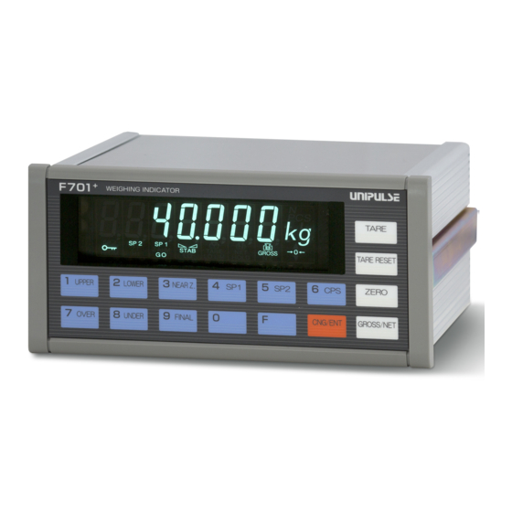
- Page 1 F701+ WEIGHING INDICATOR OPERATION MANUAL 01AUG2020REV.1.03...
- Page 2 Operation overview for F701+ Operation overview for F701+ Operation overview for F701+ Basic operation procedures Please read P.13 "2 Key Operation" Weighing settings Please read P.17 "3 Weighing" Weighing to fit the purpose Please read P.28 "4 Performing Final Discharge Control" Other useful functions Please read P.60 "6 Useful Functions"...
-
Page 3: Table Of Contents
Contents Contents Please make sure you read "Safety precautions" (pages 1 to 3) Contents 1 Before Getting Started ......... . 1 1-1. - Page 4 Contents Contents 3-3. Calibration procedure ..........18 3-4.
- Page 5 Contents Contents 4-8-3.At start NZ confirmation ..........35 4-8-4.At start weight value confirmation .
- Page 6 Contents Contents 6-11-3.Settings related to RS-485 ......... 74 6-11-4.Modbus-RTU .
- Page 7 Contents Contents 9-1. Specifications ............136 9-1-1.Analog section .
-
Page 8: Before Getting Started
1 Before Getting Started 1 Before Getting Started Chapter 1-1. Introduction Thank you for purchasing the F701+. Read this manual and understand the content prior to use. Please keep this manual ready for further use at any time. 1-2. Safety precautions Be sure to read for safety. - Page 9 1 Before Getting Started Warning Events that may cause death or severe injury to persons Chapter in cases of misuse. Design warning ● Be sure to install and fix the product to the control panel and so forth. In doing so, install a breaker so that an operator can turn power OFF immediately, and place an appropriate indication showing the breaker installation.
- Page 10 1 Before Getting Started Caution Events that may cause injury to persons or material damage Chapter in cases of misuse. Installation precautions ● Do not install the product in the following environments: - Locations where temperature or humidity exceeds specifications; - Locations subject to drastic temperature fluctuations or icing and condensation; - Outdoors or locations above 2,000m;...
-
Page 11: Unpacking Precautions
1 Before Getting Started 1-3. Unpacking precautions Chapter The attachments are packed in the carton box with the product. Take out the attachments and the product holder from the individual box. Then take out the product from the product holder as shown in the figures below. -
Page 12: Connection With Other Devices
1 Before Getting Started 1-6. Connection with other devices Chapter Printer Converters Display unit Strain gauge type sensor RS-485 (optional) RS-232C F 7 2 0 A F 7 2 0 A (optional) BCD output D/A converter (optional) (optional) PLC, DCS etc. Recording meters PROFIBUS... - Page 13 1 Before Getting Started Insert the installation rails into both sides from the rear of the indicator. Chapter Tighten securely the clasp on both sides using the included M4 screws. Caution Be sure to avoid extreme shock and/or vibration when transporting after installing the panel.
-
Page 14: Front Panel
1 Before Getting Started 1-8. Front panel Chapter (2) Units (1) Number display display (3) Status display (5) Designated keys (4) Setting keys (1) Number display The following three kinds of information are displayed. 1) Weight value display Gross weight (GROSS) or net weight (NET) is displayed. In case of a Calibration Error or Sequence Error, error display and weight value are displayed alternately. -
Page 15: Rear Panel
(4) SI/F terminal block This serial interface (SI/F) terminal block is used to connect printers, external display units, data converters, etc. made by UNIPULSE. (5) Connector for external I/O signal This connector is used to input and output external signals. I/O circuits and internal circuits are electrically insulated by photo-coupler. -
Page 16: 1-10.Connection Procedure
1 Before Getting Started 1-10. Connection procedure Chapter The following are precautions related to connection to the signal I/O terminal block. Connect this product having understood the content accurately. Warning - Do not connect commercial power supply directly to the signal I/O terminal. - To avoid electric shock when connecting to the signal I/O terminal, connect the product when power is off. -
Page 17: 1-11.Load Cell Connection
1 Before Getting Started 1-11. Load cell connection Chapter The excitation voltage of the F701+ is 10V, the maximum current is 120mA, and up to four 350Ω load cells can be connected in parallel. Load cell connector Connector pin assignments of load cell Pin no. -
Page 18: Load Cell Parallel Connection
1 Before Getting Started Caution Chapter - The F701+ excitation voltage is 10V. Heat and/or breakdown may result if the maximum excitation voltage of a load cell is not 10V or more. - Be sure to connect +EXC and +S with -EXC and -S in case a four-line type load cell is used with the F701+. -
Page 19: 1-12.Protective Grounding Connection
1 Before Getting Started 1-12. Protective grounding connection Chapter The grounding pole for the input connector of the AC power supply is the protective grounding. Warning - The rating of the AC cable included is AC125V, 10A. Prepare a separate AC cable if the product is used at a voltage higher than the rating or is used overseas. -
Page 20: Key Operation
2 Key Operation 2 Key Operation 2-1. Front panel and setting mode configuration chart Chapter The setting keys consist of nine setting modes. In each setting mode, one function is assigned to each of keys 1 to 9. (2) Units (1) Number display display (3) Status... -
Page 21: How To Use The Keys
2 Key Operation 2-2. How to use the keys How to use the setting keys ■ (Function key) This function key is used to switch between setting modes. Chapter (Numeric keys) These are used to change the settings. How to use the one-touch keys ■... -
Page 22: Selection Procedure For The Setting Mode
2 Key Operation 2-3. Selection procedure for the setting mode Change the setting in the order of "Selection of setting mode" → "Selection of setting item" → "Registration of setting value". ■ Specified basic operation of setting mode and setting items Chapter ..Switches to the specified [Selection of setting mode]... -
Page 23: (Example 2: Setting From Numerical Value Input)
2 Key Operation Once the correct setting value is input, press the key to confirm the setting value. Once the setting is complete, the display returns to show the setting mode number and the current weight value display. Current setting mode number Setting is now complete. -
Page 24: Weighing
3 Weighing 3 Weighing 3-1. Calibration "Calibration" means matching the F701+ with load cells. There are two types of calibration procedure, "actual load calibration" and "equivalent calibration". <Actual load calibration> ..Calibration by applying actual weight or pressure to the sensor Chapter <Equivalent calibration>... -
Page 25: Calibration Procedure
3 Weighing 3-3. Calibration procedure Turn OFF the LOCK switch on the rear panel to enable calibration. Turn OFF hardware LOCK Release the setting value LOCK (Lock2) that prohibits calibration. Software LOCK release Units display Set the units to display. Chapter (Setting mode 3-7) Decimal place Set the decimal place. -
Page 26: Settings And Operations Related To Calibration
3 Weighing 3-4. Settings and operations related to calibration 3-4-1.Setting value LOCK The LOCK can be activated to prevent calibration and setting values from being changed due to operational errors. There are two types of LOCK: hardware LOCK and software LOCK. Both LOCKs must be disabled during calibration. -
Page 27: 3-4-7.Gravitational Acceleration (Setting Mode 3-8)
3 Weighing 3-4-7.Gravitational acceleration (Setting mode 3-8) This function corrects weight discrepancies [Gravitational acceleration] (Setting mode 3-8) when scale calibration region installation region differ based on the different (Input range: 9.7500 to 9.8500) gravitational accelerations of each region. Setting is not required when the calibration and installation regions are the same. Actual load calibration is performed after searching from within the below gravitational acceleration chart for the acceleration of the region in which actual load calibration is to be performed and setting the corresponding value. -
Page 28: 3-4-8.1/4 Scale Division (Setting Mode 3-7)
3 Weighing 3-4-8.1/4 scale division (Setting mode 3-7) This function detects the center point of the [Function selection] (Setting mode 3-7) scale interval of the indicated value. " " is 1/4 scale division displayed if the indicated value is at its center 0: OFF point after further dividing the min. -
Page 29: 3-4-11.Equivalent Calibration
3 Weighing 1. Place the weight that was set as the balance weight value (setting mode 3-1) onto the load cell (scale). (Calibration using 50% of the capacity or more is favorable for linearity.) 2. Select setting mode 9-1 (span calibration). 3.(Setting Mode 9-2) -
Page 30: Tuning The Display And Internal Functions
3 Weighing 3-5. Tuning the display and internal functions Built-in functions for easier use when actually measuring etc. after completing calibration are described below. Select the most appropriate value for the kind of measurement and the setting environment. 3-5-1.Display update rate (Setting mode 3-7) Set the rate of indicated value update per [Function selection] (Setting mode 3-7) second. -
Page 31: 3-5-5.Moving Average Filter (Setting Mode 4-8)
3 Weighing 3-5-5.Moving average filter (Setting mode 4-8) This filter takes the moving averages of the A/D [Moving average filter] (Setting mode 4-8) converted data and reduces fluctuation of indicated values. The setting for the moving Signal input range average rate depends on the setting for the A/D A/D convert rate500 times/sec: 1 to 512 convert rate. -
Page 32: 3-5-8.Zero Tracking (Zt) (Setting Mode 2-8)
3 Weighing 3-5-8.Zero tracking (ZT) (Setting mode 2-8) Zero tracking is a function that sets the gross [Zero tracking] (Setting mode 2-8) weight value to 0 (zero) automatically when the - condition that the travel of zero point is within the set tracking range continues for the set Change range from zero point period of time or longer. -
Page 33: 3-5-10.Dz Regulation Value (Setting Mode 3-6)
3 Weighing Perform the following measures if zero error has occurred. Measures Change the setting value of DZ regulation value, and perform digital zero operation again. (However, this procedure is meant as a temporary action; perform zero calibration at the earliest convenience.) Remove weighing residue attached to the tank and so forth. -
Page 34: 3-5-13.One-Touch Tare Subtraction Reset
3 Weighing 3-5-13.One-touch tare subtraction reset This is a function that resets tare subtraction. If this operation is performed, tare weight can be cleared using the one-touch tare subtraction operation. 1. Press the key. 2. Tare subtraction is reset. 3-5-14. Preset tare subtraction (Digital tare subtraction) (Setting mode 1-9, 2-3) This is a function that subtracts a given setting [Weighing function 3] (Setting mode 2-3) Chapter... -
Page 35: Performing Final Discharge Control
4 Performing Final Discharge Control 4 Performing Final Discharge Control Final discharge control is a procedure to control discharge of raw material for each final from tanks such as hoppers. A constant amount can be accurately discharged by appropriately combining control settings such as final/set point 2/set point 1/compensation, judging settings such as over/under/go and timer settings such as comparison inhibit/judging and so on. -
Page 36: Setting Procedures
4 Performing Final Discharge Control 4-3. Setting procedures Select the feeding/discharging control. Selecting a discharge procedure (Setting mode 2-1) Select simple comparison/sequence mode. Selecting a control procedure (Setting mode 2-4) Comparison setting Select the net and gross weight. (Setting mode 2-1, 2-2) Judgment settings Make selections for weighing comparison and judging. -
Page 37: Auto Free Fall Compensation
4 Performing Final Discharge Control 4-6. Auto free fall compensation This function is used to automatically compensate for of compensation, a major factor in weighing errors, and to perform accurate weighing. After set point 3 is complete, the weighing value is sampled when the complete signal turns ON. -
Page 38: 4-6-1.Auto Free Fall Compensation
4 Performing Final Discharge Control Key point The compensation function will not work if number of times for judging is set to zero times (no judging). Set the number of times for judging to once or more when using auto free fall compensation function. Values of number of times for auto free fall and free fall compensation counter become 0 when compensation setting value is changed. -
Page 39: 4-7-2.Upper/Lower Limit Comparison
4 Performing Final Discharge Control 4-7-2.Upper/lower limit comparison Upper limit and lower limit can be arbitrarily [Upper/lower limit] (Setting mode 0-1/0-2) set. Set the target weight for comparison with (Input range: 0 to 99999) upper/lower limit comparison weight. In addition, set the timing of comparison in [Weighing function 1] (Setting mode 2-1) upper/lower limit comparison mode. -
Page 40: 4-7-4.Judging Time/Comparison Inhibit Time
4 Performing Final Discharge Control 4-7-4.Judging time/Comparison inhibit time Comparison can be inhibited for a certain period [Comparison inhibit time 1/judging time/ of time to prevent inappropriate control comparison inhibit time 2] (Setting mode 1-1/1-2/1-8) operation due to mechanical vibration caused by valve opening/closing. -
Page 41: Sequence Control Settings
4 Performing Final Discharge Control 4-8. Sequence control settings Set various parameters to perform a series of operations from weighing start to weighing complete. Normal sequence control This is a control procedure to begin weighing by weighing start signals and to end weighing by outputting complete signals. -
Page 42: 4-8-3.At Start Nz Confirmation
4 Performing Final Discharge Control 4-8-3.At start NZ confirmation This setting is used to check whether or not near [Sequence mode] (Setting mode 2-4) zero signal is ON when starting weighing. Weighing starts normally if near zero is ON; Sequence control 1: At start NZ confirmation ON Seq. -
Page 43: 4-8-7.Restart Setting (Sp1, Sp2, Sp3)
4 Performing Final Discharge Control 4-8-7.Restart setting (SP1, SP2, SP3) This parameter determines the restarting [Restart setting] (Setting mode 5-3, 5-4, 5-5) condition for the weighing operation of F701+. (Input range: 0 to 100) The restarting condition on restart can be set as SP1 range Setting mode 5-3 SP2 range Setting mode 5-4 percentages (%) of the ranges of each of SP1... -
Page 44: External I/O Signal (Control Connector)
4 Performing Final Discharge Control 4-9. External I/O signal (control connector) I/O circuits and internal circuits are electrically insulated by photo-coupler. An external DC24V (power source for the external I/O signal circuit) must be prepared separately. 4-9-1.Connector pin assignments Compatible connector: 57-30240 manufactured by DKK Signal Signal COM (sink type)/+24V(source type) -
Page 45: 4-9-3.Connecting An External Control Device
4 Performing Final Discharge Control 4-9-3.Connecting an external control device The external input signal and external output signal can only be connected to either the sink type or the source type. Please specify when placing an order. <Equivalent circuit and connection example for when sink type is specified> - Input Signal input circuit inputs signal by making the short-circuit and open-circuit between input terminals and the COM terminal. -
Page 46: 4-9-4.External Input Signal
4 Performing Final Discharge Control <Equivalent circuit and connection example for when source type is specified> - Output The signal output circuit is a photo-coupler insulated output (current source type). F701+ PLC etc. +24V Source type [No.1, 13] Input Output [No.6 to 11, 18 to 23] [No.12, 24] Chapter +24VRTN... - Page 47 4 Performing Final Discharge Control <Level input> Switches processes when external input is switched between ON and OFF. Example) Feed/discharge switching When external input is OFF Feeding control Feeding control Discharging control When external input is ON Discharging control Undefined section (within 50msec) When processing is executed while external input is ON.
- Page 48 4 Performing Final Discharge Control Signal Explanation Comparison judge is performed while this is turned ON during simple comparison control. This input terminal becomes HOLD in accordance with setting. This signal cannot be used as JUDGE unless over/under comparison mode JUDGE or upper/lower limit comparison mode is set as "comparison is made when the judging input is ON".
-
Page 49: 4-9-5.External Output Signal
4 Performing Final Discharge Control 4-9-5.External output signal Signal Explanation ● In simple comparison mode Conditions under which each signal turns ON are as follows: -SP1 output: Weight value ≧ final setting value - set point 1 setting value - SP2 output: Weight value ≧... - Page 50 4 Performing Final Discharge Control Signal Explanation Output turns ON when display is ±LOAD, OFL or ZALM (zero error). Weight error (Refer to P.125 "7-1.Over-scale display" for details regarding error display.) Output turns ON in seq. error. Seq. error (Refer to P.126 "7-2.Sequence error display" for details regarding seq. error.) Output turns ON when normal operation is performed.
-
Page 51: Timing Chart For Weighing
5 Timing Chart for Weighing 5 Timing Chart for Weighing An example of a timing chart for simple comparison control and sequence control. 5-1. Simple comparison control Over Final Under Final - Compensation Final - Set point 2 Final - Set point 1 Chapter 25% of final No.9... - Page 52 5 Timing Chart for Weighing Simple comparison control oper- Checking status External input signal External output Keys for relevant settings ation display to be used signal to be used Setting mode 0-4: set point 1 Setting mode 0-9: Final ON condition for set point 1 SP1 lights up Set point 1 (7 pin) ON Setting mode 2-1:...
-
Page 53: Normal Sequence Control
5 Timing Chart for Weighing 5-2. Normal sequence control Over Final Under Final - Compensation Final - Set point 2 Final - Set point 1 Near zero Time Chapter Restart input No.2 Tare subtraction input No.3 Start No.1 No.12 input No.4 output No.6 output... - Page 54 5 Timing Chart for Weighing Checking status External input signal External output Sequence control operation Keys for relevant settings display to be used signal to be used Setting mode 0-4: set point 1 SP1/SP2/SP3 Setting mode 0-9: final Waiting for input of start signal Set point 1 (7 pin) ON blinks Setting mode 2-1:...
-
Page 55: Sequence Control (With Adjust Feeding)
5 Timing Chart for Weighing 5-3. Sequence control (with adjust feeding) Over Final Under Final - Compensation Final - Set point 2 Final - Set point 1 Near zero Time No.2 Tare subtraction input No.3 Start No.1 Chapter input No.4 output No.6 output No.8... - Page 56 5 Timing Chart for Weighing Checking status External input signal External output Sequence control operation Keys for relevant settings display to be used signal to be used Waiting for start signal input SP1/SP2/SP3 blinks SP1/SP2/SP3 blinks at medium speed ↓ Setting mode 2-1: Tare subtraction (5 Execution of tare subtraction Tare lights up...
-
Page 57: Sequence Control (With External Judging)
5 Timing Chart for Weighing 5-4. Sequence control (with external judging) Over Final Under Final - Compensation Final - Set point 2 Final - Set point 1 Near zero Time No.2 Tare subtraction input No.3 Start Chapter No.1 No.14 input No.4 output No.6 output... - Page 58 5 Timing Chart for Weighing Checking status External input signal External output Sequence control operation Keys for relevant settings display to be used signal to be used Waiting for start signal input SP1/SP2/SP3 blinks SP1/SP2/SP3 blinks at medium speed ↓ Setting mode 2-1: Tare subtraction Execution of tare subtraction Tare lights up...
-
Page 59: Sequence Control (With Pause Input/Power Failure Restoration) [Case 1]
5 Timing Chart for Weighing 5-5. Sequence control (with pause input/power failure restoration) [CASE 1] Over Final Under Final - Compensation Final - Set point 2 Final - Set point 1 Restart setting SP1 80% (Final - SP1) * 0.8 Near zero Time Pause No.4... - Page 60 5 Timing Chart for Weighing Checking status External input signal External output Sequence control operation Keys for relevant settings display to be used signal to be used Waiting for start signal input SP1/SP2/SP3 blinks SP1/SP2/SP3 blinks at medium speed ↓ Setting mode 2-1: Tare subtraction Execution of tare subtraction Tare lights up...
-
Page 61: Sequence Control (With Pause Input/Power Failure Restoration) [Case 2]
5 Timing Chart for Weighing 5-6. Sequence control (with pause input/power failure restoration) [CASE 2] Over Final Under Final - Compensation Final - Set point 2 Final - Set point 1 Restart setting SP1 80% (Final - SP1) * 0.8 Near zero Time Pause input... - Page 62 5 Timing Chart for Weighing Checking status External input signal External output Sequence control operation Keys for relevant settings display to be used signal to be used Waiting for start signal input SP1/SP2/SP3 blinks SP1/SP2/SP3 blinks at medium speed ↓ Setting mode 2-1: Tare subtraction Execution of tare subtraction Tare lights up...
-
Page 63: Sequence Control (With Pause Input/Power Failure Restoration) [Case 3]
5 Timing Chart for Weighing 5-7. Sequence control (with pause input/power failure restoration) [CASE 3] Over Final Under Final - Compensation Restart setting SP3 50% (Final - compensation) * 0.5 Final - Set point 2 Final - Set point 1 Near zero Time Pause input... - Page 64 5 Timing Chart for Weighing Checking status External input signal External output Sequence control operation Keys for relevant settings display to be used signal to be used Waiting for start signal input SP1/SP2/SP3 blinks SP1/SP2/SP3 blinks at medium speed ↓ Setting mode 2-1: Tare subtraction Execution of tare subtraction Tare lights up...
-
Page 65: Sequence Control (Knocking)
5 Timing Chart for Weighing 5-8. Sequence control (knocking) Over Final Under Final - Compensation Final - Set point 2 Final - Set point 1 Near zero Time Tare subtraction input Start Chapter input output output output Comparison inhibit timer Knocking timer Knocking output First... - Page 66 5 Timing Chart for Weighing Checking status External input signal External output Sequence control operation Keys for relevant settings display to be used signal to be used SP1/SP2/SP3 Waiting for start signal input blinks SP1/SP2/SP3 blinks at medium speed ↓ Setting mode 2-1: Tare subtraction Execution of tare subtraction Tare lights up...
-
Page 67: Useful Functions
6 Useful Functions 6 Useful Functions Here are some useful functions when using F701+. 6-1. Prohibiting operation of designated keys The operation of designated keys (P.14" ■ [Function key prohibition] (setting mode 2-5) How to use the designated keys") on the front panel can be prohibited to prevent <TARE>... -
Page 68: Using The Function For Power Failure Restoration
(Check stops when there is a memory check error.) (If check stops or the display unit does not display information correctly, it is a sign of failure. Repair can be performed at UNIPULSE or at the point of purchase.) ■ Memory clear... -
Page 69: Replacing The I/O Substrate
6 Useful Functions 6-8. Replacing the I/O substrate The I/O substrate can be replaced. (1) M3 screw (1) M3 screw To replace the I/O substrate, remove the two M3 screws (1), pull out the whole control panel, and then replace. After replacement, retighten the M3 screws (1). Chapter... -
Page 70: Using The Si/F Interface
6-9. Using the SI/F interface SI/F interface is a dedicated interface for connecting external devices such as printers and large display units made by UNIPULSE. - Transmitting distance: Approx. 300 meters. - Up to three external devices can be connected with no polarity (The information to be displayed can be selected separately for each device.) -
Page 71: 6-10.Using An Rs-232C Interface (Option)
6 Useful Functions 6-10. Using an RS-232C interface (option) The details for an RS-232C interface are as follows. 6-10-1.Communication specifications ■ Standards Signal level RS-232C compliant Transmitting distance Approx. 15 m Transmitting method Asynchronous, full duplex Transmitting speed Select from 4800, 9600, 19200, 38400, 57600, 115.2k bps Bit configuration Start bit 1 bit... -
Page 72: 6-10-2.Settings Related To Srs-232C
6 Useful Functions 6-10-2.Settings related to SRS-232C ■ Settings for RS-232C I/F The setting values for the PC or PLC to be connected to and the RS-232C of the main unit must be the same. [Settings for RS-232C I/F] (setting mode 4-4) Baud rate selection 6: Printer mode Terminator... - Page 73 6 Useful Functions - Communication mode 4 Transmits gross weight once when outputting an automatic print command. Ignore all R, W, and C commands. Transmission format 1 (20 bytes) - Communication mode 5 Transmits net weight once when outputting an automatic print command. Ignores all R, W, and C commands.
-
Page 74: 6-10-4.Transmission Format
6 Useful Functions 6-10-4.Transmission format - Transmission format 1 9 10 11 12 13 14 15 16 18 19 ± CR LF Sign HEADER 5-digit gross weight + decimal point + or - - Transmission format 2 9 10 11 12 13 14 15 16 17 18 19 ±... -
Page 75: 6-10-5.Communication Format
6 Useful Functions 6-10-5.Communication format - Read gross weight (sign, 5-digit weight, decimal point) Host 1 0 0 CR LF + F701+ - Read net weight (sign, 5-digit weight, decimal point) Host 1 0 0 CR LF + F701+ - Read tare weight (sign, 5-digit weight, decimal point) Host 1 0 0 CR LF... - Page 76 6 Useful Functions - Status 3 (7 digits) Host F701+ Near zero output signal 1: ON Undefined 0: OFF Lower limit output signal 1: ON 0: OFF Upper limit output signal 1: ON 0: OFF - Status 4 (7 digits) Host F701+ Weight error output signal 1: ON...
- Page 77 6 Useful Functions - Read accumulated data Host 0 0 0 CR LF F701+ Weighed value * Up to 256 data can be saved in the memory buffer, and the data are deleted starting from the oldest when they are read. Host CR LF F701+...
-
Page 78: 6-10-6.List Of Setting Values
6 Useful Functions 6-10-6.List of setting values Use when writing or reading setting values. Fill blanks with setting values. CR LF (LOCK1 to prohibit writing) Set point 1 CR LF (LOCK1 to prohibit writing) Set point 2 CR LF (LOCK1 to prohibit writing) Final Over CR LF... -
Page 79: 6-10-7.List Of Commands
6 Useful Functions CR LF (LOCK2 and LOCK SW to prohibit writing) DZ regulation value CR LF (LOCK2 to prohibit writing) Extended function selection 1 Measurement Act compliance CR LF (LOCK2 to prohibit writing) CR LF D/A output mode (LOCK2 to prohibit writing) CR LF (LOCK2 to prohibit writing) D/A zero output weight value... -
Page 80: 6-11.Using An Rs-485 Interface (Option)
6 Useful Functions 6-11. Using an RS-485 interface (option) RS-485 is an interface to read the indicated values and status of the F701+ and to write the setting values into the F701+. This interface is convenient for processing such as controls, totals, and records by connecting the F701+ to a PLC, programmable display unit and so forth. -
Page 81: 6-11-3.Settings Related To Rs-485
6 Useful Functions ■ Two-wire (multi point) F701+ F701+ F701+ F701+ Terminator Host Twisted pair wires Terminator 6-11-3.Settings related to RS-485 ■ Settings for RS-485 I/F The setting values for the PC or PLC to be connected and RS-485 of the main unit must be the same. [Settings for RS-485 I/F] (setting mode 4-4) Baud rate selection Chapter... -
Page 82: 6-11-4.Modbus-Rtu
6 Useful Functions - If the ID no. is not "0000", other formats (R--, W--, C--, etc.) are disabled until the following start command is received. - Start command ID no. Host D 1 2 CR LF F701+ ID no. * Returns only when the ID-no. matches the number set with the keys. - Page 83 6 Useful Functions 01 (0x01) Read Coils The ON/OFF status of slave coils is read. Since it is a read command, broadcast cannot be specified. The start address of the coil and the number of coils are specified. [Request] Function 1 byte 0x01 Start address 2 bytes...
- Page 84 6 Useful Functions 02 (0x02) Read Discrete Inputs The ON/OFF status of discrete input is read. Broadcast cannot be specified. The start address of the input and the number of inputs is specified. [Request] Function 1 byte 0x02 Start address 2 bytes 0x0000 to 0xFFFF Number of inputs 2 bytes...
- Page 85 6 Useful Functions 03 (0x03) Read Holding Registers The contents of slave holding registers are read. Broadcast cannot be specified. The start address of the holding register and the number of registers are specified. Slave devices transmit data by converting the contents of each register to 2 bytes. * Be sure to specify the setting code prior to reading setting values for each item.
- Page 86 6 Useful Functions 04 (0x04) Read Input Registers The contents of slave input registers are read. Broadcast cannot be specified. The start address of the input register and the number of registers are specified. Slave devices transmit data by converting the contents of each register to 2 bytes. [Request] Function 1 byte...
- Page 87 6 Useful Functions 05 (0x05) Write Single Coil The coils of slave devices are changed to ON or OFF. When broadcast (0) is specified, coils of all slave devices with the same address will be rewritten. The coil address and output value are specified in the request. When ON...
- Page 88 6 Useful Functions 06 (0x06) Write Single Register The values of slave holding registers are changed (rewritten). When broadcast (0) is specified, holding registers of all slave devices with the same address will be rewritten. The holding register address and data to be changed are specified in the request. * Be sure to specify the setting code prior to writing setting values for each item.
- Page 89 6 Useful Functions 15 (0x0F) Write Multiple Coils For slave coils, data for a specified number of coils starting from a specified address is changed. When broadcast (0) is specified, coils of all slave devices with the same address will be rewritten. The coil address, new number of bytes and output value are specified in the request.
- Page 90 6 Useful Functions 16 (0x10) Write Multiple Registers For slave holding registers, a specified number of data are changed starting from a specified address. When broadcast (0) is specified, holding registers of all slave devices with the same address will be rewritten.
- Page 91 6 Useful Functions Example 2) Changing the upper limit for 32-bit integer data area (address 40009 to 40010) to 99999 (0x0001869F), and the lower limit (address 40011 to 40012) to 5000 (0x00001388). [Request] [Response] Function Function Start address (HI) Start address (HI) Start address (LO) Start address (LO) Register (HI)
- Page 92 6 Useful Functions 12 (0x0C) Get Comm Event Log This function is for reading the event status from slave devices. The contents of the status and the event counter are the same as status 11 (Get Comm Event Counter). Message count is the same as sub-function 11 (Return Bus Message Count) of status 08. The event log retains 64 bytes worth of messages communicated by the slave device.
- Page 93 6 Useful Functions Event log / Event details Events are categorized into four types. ◎ Receive event (when bit 7 is 1) Unused Communication error Unused Unused Character overrun Listen Only Mode (0 for F701+) Receive broadcast ◎ Transmit event (when bit 7 is 0) Transmit exception code 1 to 3 Transmit exception code 4 Transmit (write in) time out...
- Page 94 6 Useful Functions 17 (0x11) Report Slave ID The slave device returns the current status and the operation mode. The content of the response will vary according to the product. [Request] Function 1 byte 0x11 [Response] Function 1 byte 0x11 Number of bytes 1 byte Slave ID 1 byte...
- Page 95 6 Useful Functions List of sub-function codes Code Function name Command 00 (0x0000) Return Query Data Request echo 01 (0x0001) Restart Communications Option Initialize communication port 02 (0x0002) Return Diagnostic Register Request echo 03 (0x0003) Change ASCII Input Delimiter 04 (0x0004) Force Listen Only Mode Receive only mode 05 to 09...
- Page 96 6 Useful Functions 02 (0x0002) Return Diagnostic Register (not available for the F701+) The request frame is returned. [Request] Function 1 byte 0x08 Sub-function 2 bytes 0x00, 0x02 Data N x 2 bytes Arbitrary 16-bit data [Response] Request echo 04 (0x0004) Force Listen Only Mode The slave device is turned to receive only mode.
- Page 97 6 Useful Functions 12 (0x000C) Return Bus Communication Error Count The total number of CRC errors detected by a slave device is read. [Request] Function 1 byte 0x08 Sub-function 2 bytes 0x00, 0x0C Data 2 bytes 0x00, 0x00 [Response] Function 1 byte 0x08 Sub-function 2 bytes...
- Page 98 6 Useful Functions 17 (0x0011) Return Slave Busy Count (no count-up for the F701+) The count of the slave busies issued by a slave device is returned. [Request] Function 1 byte 0x08 Sub-function 2 bytes 0x00, 0x11 Data 2 bytes 0x00, 0x00 [Response] Function 1 byte...
- Page 99 6 Useful Functions ■ Error responses The slave device returns an error response without executing the command when a request from the master contains a failure. The value used for the function code is the requested function code with 0x80 added to it. Exception code is judged after the received frame.
- Page 100 6 Useful Functions Key point The slave device ignores requests from the master device and will not respond in the following cases. - When the specified slave address no. and the actual address do not match. - When the error-check code does not match. - When communication errors such as parity errors are detected.
- Page 101 6 Useful Functions ■ Data address Data type Address Data name Data format 00001 GROSS display 00002 NET display 00003 One-touch tare subtraction 00004 One-touch tare subtraction reset 00005 Digital zero 00006 Digital zero reset 00007 Hold ON 00008 Hold OFF 00009 Accumulation clear 00010...
- Page 102 6 Useful Functions Data type Address Data name Data format 30001 Status 1 30002 Status 2 16 bit 30003 Status 3 30004 Undefined 30005 Gross weight (HI) 30006 Gross weight (LO) Input register Decimal 30007 Net weight (HI) 3XXXX point 32 bits 30008 Net weight (LO) None...
- Page 103 6 Useful Functions 40045 Gen. Stan. Dev. (HI) (read only) 40046 Gen. Stan. Dev. (LO) (read only) 40047 Smp. Stan. Dev. (HI) (read only) 40048 Smp. Stan. Dev. (LO) (read only) 40049 Max. - min. (HI) (read only) No sign 32 bit 40050 Max.
- Page 104 6 Useful Functions ■ Data Data type Data name Description of data GROSS display Changes the weight display to gross weight. NET display Changes the weight display to net weight. One-touch tare subtraction Performs one-touch tare subtraction One-touch tare subtraction Reset Resets one-touch tare subtraction Digital zero Sets the gross weight to 0.
- Page 105 6 Useful Functions Set point 1 Indicates SP1. (0 to 99999) Set point 2 Indicates SP2. (0 to 99999) Final Indicates final. (0 to 99999) Auto free fall compensation Indicates auto free fall compensation regulation value. regulation value (0 to 99999) Upper limit Indicates upper limit.
- Page 106 6 Useful Functions *1: Net over, gross over, LOAD, -LOAD, ZALM *2: Status 1 Sequence error (0 to 9) Calibration error (0 to 9) Calibration process status ZALM +LOAD -LOAD OFL2 Undefined Undefined Undefined 15 14 13 12 11 10 9 - LOAD, +LOAD, ZALM: "1"...
- Page 107 6 Useful Functions - Units setting: Indicates units. Bit No. Units None - Decimal place: Indicates decimal place. Bit no. Decimal place None 0.00 0.000 *5: Gross weight, net weight, tare weight Sign Undefined Chapter Undefined Over 1/4 scale division ▼ 1/4 scale division ▲...
-
Page 108: 6-12.Using The Bcd Parallel Data Output Interface (Option)
6 Useful Functions 6-12. Using the BCD parallel data output interface (option) BCD data output is an interface to retrieve a weight value as a BCD code data. This interface is convenient for processing such as controls, totals, and records by connecting to a computer, process controller, sequencer, etc. -
Page 109: 6-12-3.Equivalent Circuit (Output)
6 Useful Functions 6-12-3.Equivalent circuit (output) Signal output circuit is open collector output. +12V F701+ Vext Inside Outside Vceo=30V (max) Ic=120mA (max) ● Internal transistor status ● Level of output pin Output data Negative Positive Output data Negative Positive In accordance with the logic switch (28 pin) 6-12-4.BCD data output Outputs the weight value in 5-digit BCD. -
Page 110: 6-12-7.Print Command Output
6 Useful Functions 6-12-7.Print command output (P.C) For reading the data, use the rising edge of pulse. P.C is output in synchronization with a complete signal for over/under comparison judgment. BCD data Data update rate Strobe range 6-12-8.Data strobe (STROBE) BCD data is updated for each A/D convert, and a strobe pulse is output in synchronization with the BCD data. -
Page 111: 6-13.Using The D/A Converter Interface (Option)
6 Useful Functions 6-13. Using the D/A converter interface (option) D/A converter is an interface to output the weight value as an electrical signal. The converter can output a current (4mA to 20mA) proportional to the weight value. The over range is ±5% of the full scale. -
Page 112: 6-14.Using The Profibus Interface (Option)
6 Useful Functions 6-14. Using the PROFIBUS interface (option) F701+ PROFIBUS I/F is explained below. Basic knowledge for PLC and PROFIBUS is required to read it. Refer to specialized materials for basic knowledge on PROFIBUS. 6-14-1.Specifications - F701+ equipped with PROFIBUS interface can be connected as a slave device for PROFIBUS field bus. -
Page 113: 6-14-3.Settings Related To Profibus
6 Useful Functions 6-14-3.Settings related to PROFIBUS ■ DWORD (long word) mode (setting mode 6-1) When the data on the address map is DWORD [PROFIBUS I/F setting] (setting mode 6-1) (long word), the position of HI and LO can be determined (initial value: 00). The content set 1: Mode 1 (in the order LO to HI words) here will be common to both IN data and OUT (PLC manufactured by Yokogawa... -
Page 114: 6-14-4.Address Map
6 Useful Functions 6-14-4.Address map This product occupies 12 bytes (6 words) of memory for OUT and 26 bytes (13 words) for IN. When assigning the address, ensure that the address is not the same as other slaves. All data used for writing and reading are handled after omitting the decimal points. - Page 115 6 Useful Functions ■ Descriptions related to OUT data ○ Write data Used when writing data using a command request. The write data is configured with a 32-bit binary (2 words) and the order of HI and LO positions changes with the DWORD mode of F701+ (setting mode 6-1).
- Page 116 6 Useful Functions Setting value Command no. Input range Writing prohibited 00000 to 61111 A/D conversion rate 100 times/sec Extended function selection 1 00000 to 71111 A/D conversion rate 500 times/sec 1 to 128 A/D conversion rate 100 times/sec Moving average 1 to 512 A/D conversion rate 500 times/sec Measurement Act compliance 0000 to 1111...
- Page 117 6 Useful Functions ○ Command bit - Gross weight/net weight display switch Changes gross weight display to net weight display at ON edge. Changes gross weight display to gross weight at OFF edge. - One-touch tare subtraction Performs tare subtraction at ON edge. - One-touch tare subtraction reset Resets tare subtraction at ON edge.
- Page 118 6 Useful Functions ■ IN data (13 words) DWORD mode F701+ → PLC Mode 0 Mode 1 15 14 13 12 11 10 9 8 7 6 5 4 3 2 1 0 (bit) 1st word Gross weight (HI) (LO) 15 14 13 12 11 10 9 8 7 6 5 4 3 2 1 0 (bit) 2nd word Gross weight...
- Page 119 6 Useful Functions 15 14 13 12 11 10 9 8 7 6 5 4 3 2 1 0 (bit) 11th word Command bit response (3)(2) (1) (1) Zero calibration response (2) Span calibration (actual load calibration) response (3) Span calibration (equivalent calibration) response 15 14 13 12 11 10 9 8 7 6 5 4 3 2 1 0 (bit) 12th word Command no.
- Page 120 6 Useful Functions - CZ Turns ON when at the actual zero point (0±1/4 scale division). Please note that when the 1/4 scale division (setting mode 3-7) is set to ON, it also turns ON at the center point of each indicated scale interval. - ▼...
- Page 121 6 Useful Functions ○ Status 3 (weighing information, LOCK status) - Decimal place (2-bit binary: 0 to 3) Indicates decimal place of F701+ (setting mode 3-7). - Units display (4-bit binary: 0 to 4) Indicates units display of F701+ (setting mode 3-7). - STAB Turns ON when the weight value is stable.
-
Page 122: 6-14-5.Procedures For Writing, Reading And Commanding
6 Useful Functions - Span calibration response Turns ON after receiving and performing span calibration (equivalent (equivalent calibration) calibration) in the command bit. Turns OFF after confirming that span calibration (equivalent calibration) in the command bit is OFF. - Command No. response Returns the same value as the command No. - Page 123 6 Useful Functions ■ Procedure for reading 1. Turn ON R/W and specify read (READ). 2. Specify the command no. for the setting value to read. 3. Perform ON edge of command request. 4. Set the setting value in the read data area on the F701+ side and turn ON command response. 5.
- Page 124 6 Useful Functions 4. When turning OFF the command bit immediately after execution, do so after confirming the response in "3". Commands which detect OFF edges and OFF levels do not require a reset to the previous status. 5. When the command bit is turned OFF, the corresponding command response will also be turned OFF.
-
Page 125: 6-15.Connecting A Printer
6 Useful Functions 6-15. Connecting a printer The F701+ can be connected to a printer to print weight values and so on in real time. 6-15-1.Printer mode Set the baud rate (setting mode 4-4: RS-232C communication setting) to 6: printer mode. By simply changing to printer mode, the settings change automatically within the device to enable it to communicate with the printer in use. - Page 126 6 Useful Functions ■ Printer settings Perform setting related to printing size and [Printer settings] (setting mode 7-3) line breaks. Line breaks after total print * Undefined (input range: 0 to 9) Double size print Line breaks after individual print 1: ON (input range: 0 to 9) 0: OFF ■...
- Page 127 6 Useful Functions ■ Print count Set print count. Also used as an accumulation [Print count] (setting mode 7-6) count setting even when not in printer mode. (Input range: 0 to 9999) ■ Year setting (setting mode 7-7) Set current year. Year between 2000 and 2099 [Print count] (setting mode 7-7) can be set.
-
Page 128: 6-15-3.Examples Of Print Format
6 Useful Functions 6-15-3.Examples of print format ■ Individual print 2 3 4 5 6 7 8 9 10 11 12 13 14 15 16 17 18 19 20 21 22 23 24 Digit No. → ↓Printer settings 3 4 5 Weight value only 9 8 7 6 With count print... - Page 129 6 Useful Functions ■ Total print 1 2 3 4 5 6 7 8 9 10 11 12 13 14 15 16 17 18 19 20 21 22 23 24 Digit No. → ↓Printer settings Total data only T O T A L 5 1 2 7 7 8 9 .
-
Page 130: 6-16.Using Statistical Data Functions
6 Useful Functions 6-16. Using statistical data functions Data accumulated in F701+ can be displayed statistically. 6-16-1.Average weight The average weight is displayed. [Average weight] (setting mode 8-1) (Display range: 0 to 99999) 6-16-2.Max. weight The maximum weight is displayed. [Max. weight] (setting mode 8-2) (Display range: 0 to 99999) 6-16-3.Min. -
Page 131: 6-16-9.Accumulated Value
6 Useful Functions 6-16-9.Accumulated value The accumulated value of measured weight [Accumulated value] (setting mode 8-9) value is displayed. Accumulated values can be stored internally from 0 to 999999999, but only (Display range: 0 to 99999) * an arbitrary 5 digits can be displayed. * The digits to be displayed can be changed by the number of accumulated display digits. -
Page 132: Troubleshooting
7 Troubleshooting 7 Troubleshooting 7-1. Over-scale display Display Error name Error content/countermeasures Signals that exceed the F701+ signal input range are input. Confirm that the load cell output does not exceed the span A/D converter input calibration range and that the cable which connects F701+ to the over load cell is not disconnected. -
Page 133: Sequence Error Display
7 Troubleshooting 7-2. Sequence error display Sequence error output turns ON. Display Error name Error content/countermeasures The stop signal is ON when the weighing start signal is turned ON. Seq. error 1 Turn OFF the stop signal and re-input a start signal to start weighing. This is displayed when the stop signal turns ON while weighing with Seq. -
Page 134: Calibration Error Display
7 Troubleshooting 7-3. Calibration error display Display Error content Countermeasures The amount of initial tare elimination exceeds the zero adjustment range of F701+. Confirm that there is no unnecessary load applied to the load cell. If an error is displayed while a normal load is applied, connect a resistance between +EXC and -SIG terminals of the load cell. - Page 135 7 Troubleshooting Load cell output value has not reached the span adjustment range of F701+. Calibration Confirm that the load is applied to the load cell correctly or that the load cell error 6 output is capable of reaching the span adjustment range, and then re-perform span calibration.
-
Page 136: List Of Setting Items
8 List of Setting Items 8 List of Setting Items Initial value: Factory default value Per code: Change the setting value per code NOV.RAM: Setting values are saved in NOV.RAM (non-volatile RAM). F-RAM: Setting values are saved in F-RAM (non-volatile RAM). Lock1 (soft): Setting value change is prohibited using Lock1 of the soft switch (setting mode 2-9). - Page 137 8 List of Setting Items Setting mode 2 ■ Initial Lock1 Lock2 LOCK Display Communication Name Setting range value (soft) (soft) (SW) only command Weighing function 1 0000 0000 to 2224 W31(R/W) 2: External selection Discharging control mode 1: Discharge control 0: Feeding control 2: Comparison OFF Final and over/under...
- Page 138 8 List of Setting Items Sequence mode 0000 0000 to 2111 W30(R/W) 2: Sequence mode (with power failure restoration) Weighing mode 1: Sequence mode (without power failure restoration) 0: Simple comparison mode ◎ 1: ON Adjust feeding 0: OFF At start near zero 1: ON confirmation 0: OFF...
- Page 139 8 List of Setting Items Setting mode 4 ■ Initial Lock1 Lock2 LOCK Display Communication Name Setting range value (soft) (soft) (SW) only command D/A output mode 00 to 21 W50(R/W) 2: 20mA fixed output Test mode 1: 4mA fixed output ◎...
- Page 140 8 List of Setting Items Extended function selection 1 00000 00000 to 91111 W48(R/W) (A/D conversion rate 100 times/sec) 6: Once/sec 5: Twice/sec 4: 5 times/sec 3: 10 times/sec 2: 20 times/sec 1: 50 times/sec 0: 100 times/sec BCD data update rate (A/D conversion rate 500 times/sec) 7: Once/sec...
- Page 141 8 List of Setting Items Setting mode 5 ■ Initial Lock1 Lock2 LOCK Display Communication Name Setting range value (soft) (soft) (SW) only command Input selection 93210 00000 to 99999 W60(R/W) Input selection 5 9: Tare reset 8: Pause Input selection 4 7: Erase print Input selection 3 6: Total print...
- Page 142 8 List of Setting Items Printer settings 0000 0000 to 0199 W72(R/W) Undefined Double size print 1: ON 0: OFF ◎ Line break after individual 0 to 9 print Line break after total print 0 to 9 Individual print format 00000 00000 to 11111 W73(R/W) Count 1: ON...
-
Page 143: Specifications
9 Specifications 9 Specifications 9 Specifications 9-1. Specifications 9-1-1.Analog section DC10V±5%, output current 120mA or less, remote sensing type Load cell power supply (Up to four 350Ω series load cells can be connected in parallel.) Automatically adjusted by digital computation Zero adjustment range -0.5 to 2.0 mV/V Automatically adjusted by digital computation Span adjustment range... -
Page 144: 9-1-4.External Signal Input/Output
ON when transistor is ON. 9-1-5.Interface (standard equipment) Dedicated two-wire serial interface (SIF) This interface can be used to connect printers, external display units Description and so on made by UNIPULSE. Transmitting method Asynchronous Transmitting speed 600 bps 9-1-6.Interface (option) -
Page 145: 9-1-7.General Performance
9 Specifications RS-485 communication interface (485) This interface enables a longer distance communication compared to Description RS-232C. Furthermore, multiple F701+ units can be connected in parallel by setting ID nos. Signal level RS-485 compliant Transmitting distance Approx. 1km Transmitting method Asynchronous, half duplex Transmitting speed Select from 4800, 9600, 19200, 38400, 57600, 115.2kbps Start bit:... -
Page 146: External Dimensions
9 Specifications 9-2. External dimensions Unit: mm [Front] [Side] [Rear] Chapter... -
Page 147: Block Diagram
9 Specifications 9-3. Block diagram Chapter... -
Page 148: Compliance With Ec Directives
9 Specifications 9-4. Compliance with EC Directives F701+ is a product which meets CE requirements. Follow the instructions below when using. The F701+ Weighing Indicator is a CE-marked product that complies with EC Directives (based on the European Community Council). ( ) Overvoltage category II - Low voltage directive EN61010-1:2010...
Need help?
Do you have a question about the F701+ and is the answer not in the manual?
Questions and answers