Table of Contents
Advertisement
Quick Links
Advertisement
Table of Contents

Related Manuals for Unipulse UPM100


Summary of Contents for Unipulse UPM100
- Page 1 UPM100 POWER MONITOR OPERATION MANUAL 10JUN2015REV.1.02...
- Page 2 Read this manual and understand the contents prior to using in order to utilize the UPM100 top caliber functions fully and safely. Keep this operation manual in a safe place to be used for further reference.
- Page 3 ● Prepare a safety circuit outside the UPM100 so that the entire system functions safely if the UPM100 fails or malfunctions. ● Be sure to contact our sales representative before use if the UPM100 will be used in the following situations: - In an environment not described in the operation manual;...
- Page 4 OFF. ● Use only after warming up for 30 minutes or longer following the start of power supply. ● Protective performance of the UPM100 may be lost if it is not used as specified. ● Cleaning - Unplug the power supply when cleaning.
- Page 5 Built-in lithium battery Built-in lithium battery Built-in lithium battery Warning Events that may cause death or severe injury to personnel in case of misuse. ● Do not disassemble, apply pressure and deform, throw it into fires, and so forth. The battery may explode, ignite or leak.
-
Page 6: Table Of Contents
1-1. Main features of the UPM100........ - Page 7 Contents Contents Favorite indication display ......... . 33 How to save the favorite indicated value display .
- Page 8 9-3. UPM100 block diagram ........
- Page 9 Contents Contents M E M O VIII VIII...
-
Page 10: Outline
● Measurements in between seven seconds before and three seconds after the alarm is detected are recorded in the UPM100. ● Data recorded in the UPM100 can be exported to a USB memory in form of text data. 1-2. Package contents and accessories The following items are included in the package box. -
Page 11: Connection With Other Devices
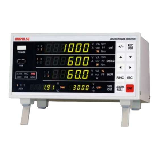
1 Outline 1-3. Connection with other devices Chapter 1-4. Part names and functions Front panel Status Main display section Setting keys Power switch USB memory connector Sub display section Unit display... - Page 12 Lower (five digits including signs) WU interphase voltage or average interphase voltage (V), W phase current or average phase current (A), power factor (PF), efficiency (%) * Refer to P.4 "UPM100 list of displays". Sub display section The next information is displayed.
- Page 13 Lights on when displaying average interphase voltage, average phase current, effective power, reactive power, apparent power and power factor. AUX: Lights on when displaying external input (voltage and temperature). * Refer to P.4 "UPM100 list of displays". UPM100 list of displays Display position Unit...
- Page 14 1 Outline Setting keys Chapter These keys are for specifying various settings and operations. Select the unit to be indicated on the upper display. Press the keys and configure the settings of the UTMⅡ to connect. FUNC SYSTEM Select the unit to be indicated on the middle display. Press the SYSTEM keys and configure the settings related to initial...
-
Page 15: Rear Panel
Input terminal for measuring electric power Power supply input connector Connect the included dedicated AC adapter for the UPM100. Input power is AC100 to 240V (-15%, +10%), free power supply. Frequency is 50/60Hz. * Refer to P.9 "2-1.Connecting the power input connector". - Page 16 Connect the K type thermocouple. Two sets can be connected. * Refer to P.14 "2-6.Connecting the thermocouple". RS-232C connector RS-232C connector for reading the indicated value and status of the UPM100, and writing the setting value to the UPM100. * Refer to P.15 "2-7.RS-232C interface connection".
-
Page 17: Connection
● Do not touch the I/O terminal while power is on. This may cause electric shock and malfunction. ● To prevent danger, perform protective grounding of the UPM100 before connecting measurement wires. ● When connecting the measurement target, turn its power off. Connecting and disconnecting measurement wires without turning the measurement targets power off is extremely dangerous. -
Page 18: Connecting The Power Input Connector
2 Connection 2-1. Connecting the power input connector Connect the dedicated AC adapter of the UPM100 to the power input connector of the main unit. Chapter 2-2. Connecting protective grounding terminals This grounding terminal is for preventing electric shock accidents. Use thick electric wire (approx. 0.75 mm ) for ground wires and be sure to ground. -
Page 19: Connecting The Measurement Circuit Of Electric Power
2 Connection 2-3. Connecting the measurement circuit of electric power Connect the main unit and electric wire to the electric power measurement terminal. Before connecting to the terminal, attach a crimping terminal with a diameter of 8mm or shorter in Chapter order to prevent the tip of the cable from scattering. -
Page 20: Three-Phase Three-Wire Type (3P3A)
2 Connection Three-phase three-wire type (3P3A) U:IN U:OUT V:IN V:OUT Chapter W:IN W:OUT M:Motor 2-4. Connecting the UTMⅡ The UTMⅡ can be easily connected using the included dedicated cable. The dedicated cable has no directionality. Connect UTMⅡ while paying attention to the direction of the connector. ●... -
Page 21: Connecting External I/O
The recommended tightening torque value is 0.5Nm. Slightly pull the electric wire to check that it does not detach. Insert the plug with the electric wire connected to the UPM100 main unit and tighten the screws (two locations). - Connecting external output (sink type) External output circuit is an open collector. - Page 22 COM terminal. Short-circuit is performed by contacts (relays, switches and so on) and non-contacts (transistors, TTL of open collector output and so on). Open circuit → OFF UPM100 interior +24V Short circuit → ON TTL open collector output...
-
Page 23: Connecting The Thermocouple
Tighten screws using a screwdriver. The recommended tightening torque value is 0.5Nm. Slightly pull the electric wire to check that it does not detach. Insert the plug with the electric wire connected to the UPM100 main unit and tighten the screws (two locations). -
Page 24: Rs-232C Interface Connection
2 Connection 2-7. RS-232C interface connection The RS-232C connector is a D-SUB 9 pin male connector. Plugs equivalent to OMRON manufactured XM2D-0901 (Cover:XM2S-0913<with Inch screw #4- 40>) will meet the requirement. Chapter Refer to P.55 "8-5.RS-232C interface". -
Page 25: Setting Procedures
3 Setting Procedures Setting Procedures 3-1. Setting mode configuration Alarm/ ALARM Data clear mode RST/. Indicated value display Select data to clear Chapter FUNC Capacity System Record SYSTEM setting mode setting mode setting mode UTMⅡ capacity setting Displayed only when two target selection UTMⅡ... - Page 26 3 Setting Procedures Chapter Voltage output Alarm USB data ALARM setting mode setting mode transfer mode RST/. Voltage output Alarm detection USB data transfer Displayed only when channel setting item setting 1 selection there is recorded data and a USB memory is connected.
-
Page 27: Key Operation
3 Setting Procedures 3-2. Key operation <<Setting procedures>> Returns to the indicated value The FNC lamp lights on. FUNC Chapter Setting mode selection ALARM SYSTEM RST/. "cal" representing "SYS" representing "mEm" "voL" representing "ALSEt" "uSb" representing capacity system representing record voltage output representing USB data setting mode... - Page 28 3 Setting Procedures <<Status of selected status mode>> [Capacity setting mode] [System setting mode] Σ Σ Σ Σ ALARM ALARM Σ Σ MEAN MEAN 2 Σ 2 Σ Chapter °C °C °C °C [Record setting mode] [Voltage output setting mode] Σ Σ...
-
Page 29: Opening Setting Mode
3 Setting Procedures 3-3. Opening setting mode e.g.) When setting the date and time Press the FUNC key while the indicated value is displayed. Σ The FNC lamp lights on. Σ ALARM Σ MEAN Σ Chapter °C °C Press the key to select system SYSTEM setting mode. -
Page 30: Utmⅱ Capacity Setting
4 UTM Ⅱ Capacity Setting UTMⅡ Capacity Setting 4-1. UTMⅡ capacity setting procedures (torque) Perform capacity setting by following the procedures below. (This cannot be performed when UTMⅡ is not connected.) (1) UTMⅡ capacity Selecting the UTMⅡ to perform capacity setting is required setting target selection only when there are two UTMⅡ... - Page 31 4 UTM Ⅱ Capacity Setting (1) UTMⅡ capacity setting target selection Select the UTMⅡ to set capacity. (However, this applies only when two UTMⅡ units are connected.) Returns to indicated value display after showing "CALErr" if UTMⅡ is not connected. <<Setting value>> IN-1: UTM1 side IN-2:...
- Page 32 4 UTM Ⅱ Capacity Setting (3) UTMⅡ capacity setting Select a type of the UTMⅡ connected. <<Setting value>> ----, 0.05, 0.1, 0.2, 0.5, 1, 2, 5, 10, 20, 50, 100, 200, 500, 1000, 2000, 5000, 10000 [Nm] * Rated output value, rated capacity value and pulse rate can be set when "----" is selected. ◇...
- Page 33 4 UTM Ⅱ Capacity Setting Set the "Rated output value". The most significant digit will flash. Σ Confirm the specifications of the sensor in Σ use, press the △ keys to enter the ▽ ALARM Σ MEAN rated output value (V). 2 Σ...
- Page 34 4 UTM Ⅱ Capacity Setting Press the key at the least significant digit to move to the most significant digit. Press the key at the most significant digit to move to the least significant digit (initial value: 1.0000Nm). Pressing the ☆ / - key will reverse the sign.
- Page 35 4 UTM Ⅱ Capacity Setting (7) Absolute value mode It is possible to set the torque value and driving force value to absolute value. <<Setting value>> OFF: With sign Absolute value ◇ How to set the absolute value mode Select UTMⅡ capacity setting mode. Set the "(1) UTMⅡ...
- Page 36 4 UTM Ⅱ Capacity Setting e.g.) When set at "2rpm" Since waiting for pulse detection for the duration of maximum detection time is required when rotation stops suddenly from high speed status, the previous rotation speed is not updated; therefore, the display will become 0 rpm after the display of the rotation speed that was last detected has held for 7.5 seconds.
- Page 37 4 UTM Ⅱ Capacity Setting (9) Rotation stop mode Cut-off looks unclear when the rotation stops suddenly due to the constraint of maximum detection time corresponding to the minimum input rotation speed. For this reason, 0 rpm display can be forcibly set with "the cycle of the rotation speed last detected x a certain multiple". <<Setting value>>...
- Page 38 4 UTM Ⅱ Capacity Setting ◇ How to set the rotation stop mode Select UTMⅡ capacity setting mode. Set the "(1) UTMⅡ capacity setting target selection". * Performed only when two UTMⅡ are connected. Perform "(2) Zero calibration". Perform procedure "(3) UTMⅡ capacity setting". Set the "(4) Rated output value setting".
-
Page 39: Function Description Related To Indicated Values
5 Function Description Related to Indicated Values Function Description Related to Indicated Values 5-1. Indicated values Voltage/current/electric power (effective/reactive/apparent)/ power factor Voltage Each interphase voltage and average interphase voltage of electric wires are displayed. RMS (true root mean square value) and MEAN (RMS value calibrated by average rectification) can be selected. -
Page 40: Torque/Rotation Speed/Driving Force
5 Function Description Related to Indicated Values Power factor The power factor is the proportion of effectively used electric power to the entire electric power. The effective power of the apparent power. Status ∑ Display unit Torque/rotation speed/driving force Status 1: UTM1 input 2: UTM2 input Torque Analog signals (±5V) from UTMⅡ... -
Page 41: Temperature/External Voltage Input (Aux)
5 Function Description Related to Indicated Values Temperature/external voltage input (AUX) Temperature The analog signal from Type K thermocouple is calculated to temperature and displayed. (-200 to 1300°C) Status 1: TEMP1 2: TEMP2 Display unit °C External voltage input (AUX) The ±5V input between the COM and AUX is displayed as ±5.000 (V). Status 1: AUX1 2: AUX2 Display unit... -
Page 42: Favorite Indication Display
5 Function Description Related to Indicated Values Sub display section Press the key to change the content displayed. 1) (∑) Right side: Average interphase voltage [V] Left side: Average phase current [A] → 2) (1) Right side: UTM1 torque [Nm] Left side: UTM1 rotation speed [rpm] →... -
Page 43: Digital Filter
5 Function Description Related to Indicated Values 5-2. Digital filter This filter takes the moving averages of converted data and reduces fluctuation of indicated values. The fluctuation of indicated values can be reduced further by performing this function more number of times; however, response to input becomes slower. This setting is common to all indicated values. -
Page 44: Voltage Calculation Method
5 Function Description Related to Indicated Values 5-4. Voltage calculation method Set the calculation method of voltage. <<Setting value>> RMS: Calculation of the RMS value of voltage by root mean square MEAN: RMS value of voltage is calculated by RMS value calibrated by average rectification method. -
Page 45: Date And Time Setting
5 Function Description Related to Indicated Values 5-6. Date and time setting Set the date and time. Displayed as YY(year)MM(month)DD(day)hh(hour)mm(minute)ss(second). <<Setting value>> Upper: YYMMDD Middle: hhmmss How to configure the date and time setting Select system setting mode. Set the "Digital filter". Set the "Display update count". -
Page 46: Explanation Of The Alarm Detection Function
6 Explanation of the Alarm Detection Function Explanation of the Alarm Detection Function Alarm can be output as a contact signal that can be utilized for emergency stoppage of system and so on, when voltage, current or electric power exceeds the set value. Measurements in between seven seconds before and three seconds after the alarm is detected are recorded in the main unit 10 times per second. -
Page 47: How To Configure Alarm Detection Item Setting 1
6 Explanation of the Alarm Detection Function How to configure alarm detection item setting 1 Select alarm setting mode. ALARM Press the → key. FUNC RST/. Set the "Alarm detection item setting 1". Σ △ ▽ Press the key to select alarm detection item setting 1 (initial value: Σ... -
Page 48: How To Set Alarm Detection Level 1
6 Explanation of the Alarm Detection Function How to set alarm detection level 1 Select alarm setting mode. Set the "Alarm detection item setting 1". Set the "Alarm detection level 1". Σ △ ▽ Press the keys and set alarm detection level 1 (initial value: voltage Σ... -
Page 49: How To Configure Alarm Detection Item Setting 2
6 Explanation of the Alarm Detection Function How to configure alarm detection item setting 2 Select alarm setting mode. Set the "Alarm detection item setting 1". Set the "Alarm detection level 1". Set the "Alarm detection item setting 2". Σ △ ▽... -
Page 50: How To Set Alarm Detection Level 2
6 Explanation of the Alarm Detection Function How to set alarm detection level 2 Select alarm setting mode. Set the "Alarm detection item setting 1". Set the "Alarm detection level 1". Set the "Alarm detection item setting 2". Set the "Alarm detection level 2". Σ... -
Page 51: Function Description Related To Records
7 Function Description Related to Records Function Description Related to Records Selected data is recorded in the UPM100 unit. As for details on records, items set on record item setting 1 and 2 of the record setting mode are saved. As for point data and alarm detection data, items set on record item setting 1 and 2 are saved. -
Page 52: Description Of Record Setting
7 Function Description Related to Records 7-1. Description of record setting ID setting for simultaneously recording arbitrary numbers to recorded data and item selection when writing recorded data to USB memory are performed. Record ID setting This is the setting value for simultaneously saving arbitrary numbers to recorded data. <<Setting value>>... -
Page 53: Record Item Setting
7 Function Description Related to Records Record item setting This is a setting value that selects the data to be written when writing recorded data to a USB memory. <<Setting value>> Record item setting 1: 0 0 0 0 0 0 0 to 7 Turns effective power (B0) / reactive power (B1) / apparent power (B2) ON and OFF. - Page 54 7 Function Description Related to Records Record item setting 2 (15) Efficiency: The proportion of driving force obtained from UTMⅡ and measured electric power, or the proportion of driving forces obtained from two UTMⅡ. (16) Power factor: The proportion obtained from effective power and the apparent power.
- Page 55 7 Function Description Related to Records ◇ How to configure the record item setting Select record setting mode. Set the "Record ID setting 1". Set the "Record ID setting 2". Set the "Record item setting 1". Σ △ ▽ Press the keys and select record item setting 1 (initial value: 701011).
-
Page 56: Data Recording Method
7 Function Description Related to Records 7-2. Data recording method One-push The indicated value is recorded to the point data at the timing the key was pressed. One-shot input The indicated value is recorded to the point data at the timing when a short-circuit is detected in the 2-pin (TRG1) and COM in the external I/O connector. -
Page 57: Data Transfer To Usb Memory
7 Function Description Related to Records 7-4. Data transfer to USB memory The recorded data can be saved to the USB memory. A year-month folder and a date-hour-minute-second file are created in the root directory of the USB memory. For example, when a data is copied to a USB memory at September 18, 2014, 14:00:33, it is saved to the 14Y09M folder in the root directory as 18140033.txt. - Page 58 7 Function Description Related to Records Perform data transfer to USB memory. "Fin" is displayed when the data transfer to Σ USB memory is complete. Σ Press any key to return to indicated value ALARM display. Σ MEAN 2 Σ °C °C Chapter...
-
Page 59: Standard Interface
8 Standard Interface Standard Interface 8-1. External I/O Connector pin assignments Pin number Direction Silk Signal COM (IN) +24VRTN TRG1 Recording signal one-shot input TRG2 Recording signal level input COM (OUT) +24VRTN ALARM1 Alarm detection 1 output ALARM2 Alarm detection 2 output TORQUE UTMⅡ... -
Page 60: D/A Converter Output
8 Standard Interface 8-2. D/A converter output This converter is used for obtaining an analog output linked with indicated values of the UPM100 related to UTMⅡ. The analog output range is a voltage output of -5 to +5V. Also, the output circuit and internal circuit are isolated. -
Page 61: Rotation Speed Voltage Output Full Scale Setting
8 Standard Interface ◇ How to configure the torque value voltage output full scale setting Select the voltage output setting mode. Σ "Voltage output channel setting". Σ ALARM Set the "Torque value voltage output full Σ MEAN scale setting". 2 Σ °C °C △... -
Page 62: Driving Force Value Voltage Output Full Scale Setting
8 Standard Interface * Press the key to cancel the setting and move on to the driving force value voltage output full scale setting. Driving force value voltage output full scale setting Sets the full scale of D/A output of UTMⅡ driving force value output from the 9 pin of the external I/O connector. -
Page 63: External Voltage Input (Aux)
8 Standard Interface 8-3. External voltage input (AUX) The voltage input of two points within ±5V can be synchronized with other indicated values and recorded. (Single end) Also, the input circuit and internal circuit are isolated. 0 to 5V is adjusted to 0.000 to 5.000 [V]. The resolution is approximately 1/10000 for -5.000 to +5.000V. -
Page 64: Rs-232C Interface
8-5. RS-232C interface RS-232C is an interface for reading the indicated values and status of the UPM100 and writing the setting values into the UPM100. This interface is convenient for controlling, totaling and recording by connecting the UPM100 to a computer, process controller, PLC, etc. -
Page 65: Transmission And Reception Mode
8 Standard Interface Transmission and reception mode Communication is commanded from the host. Retrieving and writing indicated value, status and setting value can be performed. I/F setting Set the I/F setting in conformity to the host. <<Setting value>> 0 0 4 1 0 0 Parity bit 0: NON, 1: EVEN, 2: ODD Stop bit... -
Page 66: Communication Format
R* replies the indicated value at the time of the request. The synchronization of the command cannot be maintained. Average electric power request RA Host ± UPM100 Average interphase voltage Average phase current Effective power Driving force value request RB Host ±... - Page 67 8 Standard Interface Temperature request RI Host ± ± UPM100 TEMP1 TEMP2 2. Transmission and reception [latch command] Recorded to latch data by latch command. Data latch request LT Host UPM100 3. Transmission and reception [reading latch data] L* command maintains the synchronism by returning the latched data by latch command.
- Page 68 8 Standard Interface Request of UTM1 torque and rotation speed of latch LF Host ± UPM100 UTM1 Torque Rotation speed Request of UTM2 torque and rotation speed of latch LG Host ± UPM100 UTM2 Torque Rotation speed Request of latch external voltage input LH Host ±...
- Page 69 8 Standard Interface Rotation speed setting Minimum input rotation speed When 4-PUL0:15rpm, 1:10rpm, 2:5rpm, 3:3rpm, 4:2rpm When 1-PUL0:60rpm, 1:40rpm, 2:20rpm, 3:12rpm, 4:8rpm Rotation stop mode 0: OFF, 1: twice, 2: 4 times, 3: 8 times 4: UTM1, 9:UTM2 Digital filter 0:0(OFF), 1: twice, 2: 4 times, 3: 8 times, 4:16 times System settings Display update count 0:10PPS, 1:2PPS...
- Page 70 8 Standard Interface Voltage output channel setting 0:IN-1, 1:IN-2 Torque value voltage output full scale setting Five-digit, decimal point Rotation speed voltage output full scale setting Five digits Driving force value voltage output full scale setting Five-digit, decimal point Alarm detection item setting 1 (1) Invalid (1) 0 fixed (2) Turns UV interphase voltage (B0) VW interphase voltage (B1)
- Page 71 8 Standard Interface 5. Transmission and reception [operation command] UTMⅡ zero calibration CA Host UPM100 Calibrates the zero of the UTMⅡ torque value. (1) :1 or 2 1:UTM1 side 2:UTM2 side Valid setting of the number of pulses CP Host UPM100 Enables the setting of the number of pulses in the UTMⅡ.
-
Page 72: Usb Memory Interface
USB memory interface This is an interface for exporting the data accumulated in the UPM100 to the USB memory. It can be referenced and saved by using a PC. When an ID or serial is set, it can be used for... -
Page 73: Specifications
9 Specifications Specifications 9-1. Specifications Analog section Electric power measurement section Measurement line Single phase two-wire (1P2W: measure one point of both interphase voltage and phase current) Three-phase three-wire (3P3W: measure two points of both interphase voltage and phase current) Input method Voltage Resistance dividing method Current... - Page 74 9 Specifications Each measurement points of voltage and computing equation of sum value 1P2W Each measurement point Σ (i)s 3P3W sum value (UV) (VW) (WU) Note) The aforementioned case applies to RMS value. In case of average rectified value calculated by RMS and simple average value, U is replaced with U mn(i)
- Page 75 9 Specifications Each measurement point of electrical power and computing equation of sum value 1P2W Each measurement point Σ × (i)s (i)s 3P3W sum value (UV) (VW) Each measurement point of apparent power and computing equation of sum value 1P2W Each measurement point × 3P3W sum value Each measurement point of reactive power and computing equation of sum value 1P2W Each measurement point...
-
Page 76: Display Section
9 Specifications Pulse input for rotation speed (open collector input) Maximum input rotation speed Equivalent to the output frequency of the UTMⅡ series Minimum input rotation speed Selected from 15, 10, 5, 3 and 2 rpm * when pulse rate is 4 pulse. Selected from 60, 40, 20, 12 and 8 rpm * when pulse rate is 1 pulse. -
Page 77: Interface
85%RH or less (no condensation) Dimensions 220 (W) ×110 (H) × 160 (D) mm (not including protruding sections) Weight Approx. 2.0kg Accessories - UPM100 dedicated AC adapter 1.8m ......1 - Dedicated cable for UTMⅡ connection 2m....2 - Operation manual ............1... -
Page 78: External Dimensions
9 Specifications 9-2. External dimensions Chapter... -
Page 79: Upm100 Block Diagram
9 Specifications 9-3. UPM100 block diagram Chapter... -
Page 80: 10Appendices
10 Appendices Appendices 10-1. List of setting values * Initial value Factory default value * NOVRAM Saved in NOVRAM ◎: None: Saved in SRAM (backed up by lithium battery) * Reference Reference page of each item description ■ Capacity setting mode ("FUNC" →"cal") Refere Setting value name Setting value range... - Page 81 10 Appendices ■ System setting mode ("FUNC" → "SYSTEM") Refere Setting value name Setting value range Initial value Digital filter 0, 2, 4, 8, 16 ◎ Display update count 10PPS, 2PPS 10 PPS ◎ Voltage calculation method RMS, MEAN ◎ Electric power measurement method 1P2, 3P3 ◎...
- Page 82 10 Appendices ■ Record setting mode ("FUNC" → "MEM") Refere Setting value name Setting value range Initial value Record ID setting 1 000000 to 999999 000000 ◎ Record ID setting 2 000000 to 999999 000000 ◎ 7 0 1 0 1 1 0 to 7 Turns effective power (B0) / reactive power (B1) /...
- Page 83 10 Appendices ■ Voltage output setting mode ("FUNC" → "VOL OUT") Refere Setting value name Setting value range Initial value Voltage output channel setting IN-1, IN-2 IN-1 ◎ Torque value voltage output full scale 0.0001 to 99999. [Nm] 10000Nm ◎ setting * The decimal point is not fixed.
-
Page 84: 10-2.Self-Check Function
10 Appendices 10-2. Self-check function Self-check is a function that automatically checks the memory and detects errors. It is also a function that performs checksum of software, operation check of NOVRAM and SRAM, and check of display lighting. This function does not diagnose the analog circuit. Self-check procedure Select system setting mode. - Page 85 10 Appendices SUB1_CPU check. The SUB1_CPU is checked and if there is Σ no problem, the version and checksum are Σ displayed. ALARM Pressing will initiate Σ MEAN SUB2_CPU check. 2 Σ °C °C Σ Σ ALARM Σ MEAN 2 Σ °C °C SUB2_CPU check.
-
Page 86: 10-3.Error Message List
10 Appendices 10-3. Error message list -LoAd Signal input range The input electric signal substantially exceeds the signal input Over by -5V range. This occurs when an excessive load is applied to the sensor, or when the input terminal becomes an open circuit due +LoAd Signal input range to cable disconnection and so forth. -
Page 87: 10-4.Troubleshooting
Communication is not possible Is the correct communication cable used? Is it properly connected? Confirm the wiring and connect the communication cable properly. Does the I/F setting match the master and UPM100? RS-232C Confirm the I/F setting and match the setting. -
Page 88: 10-5.Disposing Lithium Batteries
10 Appendices 10-5. Disposing lithium batteries When disposing the UPM100, remove the lithium batteries and make sure to dispose them according to classification of waste collection. Additionally, turn the power off and wait for a while to discharge the internal condenser.
Need help?
Do you have a question about the UPM100 and is the answer not in the manual?
Questions and answers