Table of Contents
Advertisement
Quick Links
Advertisement
Table of Contents

Related Manuals for Spectrum Controls Micro800 2085sc-IF16C


Summary of Contents for Spectrum Controls Micro800 2085sc-IF16C
- Page 1 User’s Manual Pub. 0300306-02 Rev. B...
- Page 2 No patent liability is assumed by Spectrum Controls, Inc. with respect to the use of any of the information, products, circuits, programming, or services referenced herein.
-
Page 3: Table Of Contents
Table of Contents IMPORTANT NOTES ............................... II CHAPTER 1 MODULE OVERVIEW ......................... 1-1 1.1 G ..........................1-1 ECTION ENERAL ESCRIPTION 1.2 I ..........................1-2 ECTION NPUT PECIFICATIONS 1.3 D ............................1-6 ECTION ORMATS 1.4 H ..........................1-6 ECTION ARDWARE EATURES 1.4.1 LED Blink Codes ............................ - Page 4 Micro800 16-Channel Analog Input Module 3.8 D ........................ 3-27 ECTION ECLARATION OF ONFORMITY APPENDIX A MANUALLY IMPORTING AN AOP ....................A-1 INDEX ................................. I-1 User’s Manual Pub. 0300306-02 Rev. B...
- Page 5 Micro800 16-Channel Analog Input Module Preface Read this preface to familiarize yourself with the rest of the manual. This preface covers the following topics: • Who should use this manual How to use this manual • Related documentation • • Technical support Documentation •...
- Page 6 Micro800 16-Channel Analog Input Module Allen-Bradley Refer to this Document Pub. No. Micro870 24V DC Expansion Power Supply Installation 2085-IN008 Instructions Micro850 24-Point Installing 24-point PLC Programmable Controllers 2080-IN007 Installation Instructions Micro850 48-Point Installing 48-point PLC Programmable Controllers 2080-IN008 Installation Instructions Micro870 24-Point Installing 24-point PLC Programmable Controllers...
- Page 7 Micro800 16-Channel Analog Input Module Conventions Used in This Manual The following conventions are used throughout this manual: • Bulleted lists (like this one) provide information not procedural steps. Numbered lists provide sequential steps or hierarchical information. • Italic type is used for emphasis. •...
- Page 8 Micro800 16-Channel Analog Input Module User’s Manual Pub. 0300306-02 Rev. B...
-
Page 9: Chapter 1 Module Overview
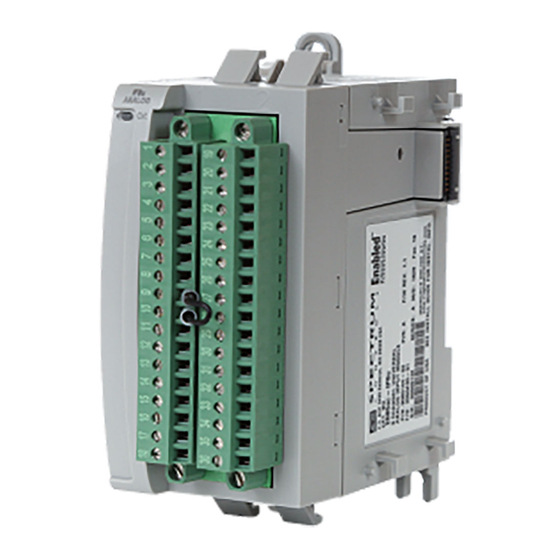
Chapter 1 Module Overview This chapter covers the following topics: • General description Input specifications • Data formats • Hardware features • • System overview The Micro800 16-Channel Analog Input Modules (2085sc-16C/16V Expansion I/O Modules) are 16-point analog modules designed to expand the local I/O capability of Rockwell Automation Micro850 and Micro870 Systems over their Expansion I/O buses. -
Page 10: Section 1.2 Input Specifications
Chapter 1: Module Overview The 2085sc-IF16C/V Expansion I/O modules measure current or voltage input data. The module supports: • Sixteen input channels. • 2085sc-IF16C module: Current measurements. The module measures the channel input current across a low-drift precision resistor, measures the voltage, and converts the voltage to a current reading. - Page 11 Chapter 1: Module Overview Input Description Value Storage/Non-Operating Humidity 5% to 85%, non-condensing Vibration/Operating 10 Hz to 500 Hz, 2 G, 0.030 max peak-to-peak Operating Shock 25 g, peak acceleration, 11±1 ms pulse, half sine Storage/Non-Operating Shock 25 g peak acceleration, 11±1 ms pulse, half sine; 35 g for panel mount.
- Page 12 Chapter 1: Module Overview Input Description Value Filters CMRR 84 dB minimum at 50 and 60 Hz for 4 Hz and 17 Hz filters NMRR 4 Hz filter 72 dB minimum at 50 and 60 Hz 17 Hz filter 62 dB minimum at 50 and 60 Hz Crosstalk -70 dB maximum Input Bias Currents and Impedance...
- Page 13 Chapter 1: Module Overview Input Description Value REACH Meets European REACH 7 requirements. Dimensions 110 mm × 87 mm × 51 mm (plastics) 110 mm × 89 mm × 51 mm (with RTBs installed.) Table 1-2. EMC Specification Table Environmental Tests Test Level Limits Radiated Emissions (Enclosure) Class A, 30 MHz –...
-
Page 14: Hardware Features
Chapter 1: Module Overview Table 1-3. Safety Test Specification Table Safety Tests Industry Standards UL 61010-2-201 Safety Requirements for Electrical Equipment for Measurement, Control, and Laboratory Use - Part 2-201: Particular Requirements for Control Equipment (NRAQ, NRAQ7) UL Safety CAN/CSA C22.2 No. 61010-1-12 (Safety Requirements for Electrical Equipment for Measurement, Control, and Laboratory Use –... - Page 15 Chapter 1: Module Overview operation are provided below. A 2085sc-IF16 module with Version 1.1 firmware uses a single, green OK LED to show power or module operational status. When startup is completed, and all internal tests have passed, the LED is solid GREEN.
-
Page 16: Section 1.5 System Overview
Calibration invalid or corrupted Factory calibration must be performed. This code will be seen for newly Return the module to Spectrum Controls, Inc. for manufactured boards that have yet to be recalibration. calibrated. Serial Number Invalid or Corrupted Serial number must be programmed. - Page 17 Chapter 1: Module Overview Block diagram: 50VAC Working RTB pins Status Reinforced 8-Input Indicator Inx+ Isolation Channels Inx- Backplane Protection, Communication Converter Channel Backplane Multiplexing, Isolator ASIC & Signal 5V DC channels Conditioning Processor (used by backplane circuitry) 8-Input Inx+ Isolated Channels 24V DC...
- Page 18 1-10 Chapter 1: Module Overview User’s Manual Pub. 0300306-02 Rev. B...
-
Page 19: Chapter 2 Installation And Wiring
Chapter 2 Installation and Wiring This chapter will cover: Compliance to European union directives • Power requirements • General considerations • • Mounting • Field wiring connections Section 2.1 Compliance to European Union Directives This product is approved for installation within the European Union and EEA regions. -
Page 20: Section 2.3 General Considerations
Chapter 2: Installation and Wiring Current rating for + 5 V is 100 mA maximum; for +24 V it is 20 mA maximum: 5 VDC 24 VDC 100 mA 20 mA Section 2.3 General Considerations The 2085sc-IF16 modules are suitable for use in an industrial environment when installed in accordance with these instructions. -
Page 21: Prevent Electrostatic Discharge
Chapter 2: Installation and Wiring 2.3.2 Prevent Electrostatic Discharge Electrostatic discharge can damage integrated circuits or semiconductors if WARNING you touch I/O expansion port connector pins or the terminal block on the module. Follow these guidelines when you handle the module: •... -
Page 22: Section 2.4 Mounting
Maintain spacing from enclosure walls, wireways, adjacent equipment, etc. Allow 50.8 mm (2 in.) of space on all sides for adequate ventilation, as shown: 2.4.2 Parts List Your package contains one Micro800 2085sc-IF16C or 2085sc-IF16V Plug-in Module and one Quick Start Guide. 2.4.3 Module Description... -
Page 23: Insert Module Next To The Controller
Chapter 2: Installation and Wiring Description Description Mounting screw hole/mounting foot Module interconnect latch Removable Terminal Block (RTB) DIN rail mounting latch RTB hold down screws I/O Status LED You can choose to wire the plug-in before inserting it into the controller or wire it once the module is secured in place. - Page 24 Chapter 2: Installation and Wiring Mounting Dimensions and DIN Rail Mounting 150 mm (5.91 in.) 44.5 mm (1.75 in.) Bus terminator 89 mm (3.50 in.) Micro850 Controller 2085sc-IF16V/C You can install the module on DIN rails of dimension 35 mm × 7.5 mm × 1 mm (EN 50 022-35×7.5), or on a panel.
-
Page 25: Wiring Diagram
Hazard of damage to the terminal connector. WARNING The Spectrum Controls RTB hold down and terminal screws must be tightened by hand using the guidelines. They must not be tightened using a power tool. Use a screwdriver of 0.8 × 2 mm and tighten to no more than 0.25 N-m (2.2 lb-in) torque. - Page 26 Chapter 2: Installation and Wiring Terminal Block Input signal descriptions are as follows: RTB1# Name Description RTB2# Name Description IN0+ Ch. 0 Voltage/Current Input IN8+ Ch. 8 Voltage/Current Input IN0- Ch. 0 Voltage/Current Return IN8- Ch. 8 Voltage/Current Return IN1+ Ch.
-
Page 27: Chapter 3 Configuring The 2085Sc-If16 Using Ccw
Chapter 3: Configuring the 2085sc-IF16 Using CCW Chapter 3 Configuring the 2085sc-IF16 Using CCW This chapter covers the following subjects: How to use Connected Components Workbench (CCW) and optionally • ModuleConfigConverter.exe software to configure the Module. • Analog Data and Status settings. •... -
Page 28: 2085 Sc -If16C And 3.3 Ccw Configuration Tab
Chapter 3: Configuring the 2085sc-IF16 Using CCW Spectrum Controls, Inc. also provides a custom configuration software utility that you may use to provide configuration settings to the profile. Section 3.2 2085sc-IF16C and 2085sc-IF16V AOP You use the module’s AOP to configure your module. The AOP is available in the CCW software. - Page 29 Chapter 3: Configuring the 2085sc-IF16 Using CCW The Module Profile Tool window appears. If necessary, confirm with the Windows operating system that you wish to run the software. 3. Select the row showing the module catalog name (16C is example used here, but this information is applicable to both modules), and then click the View button.
- Page 30 Chapter 3: Configuring the 2085sc-IF16 Using CCW 16V: The first tab of the window provides the module identity information. This information is described in greater detail in Module Identity, later in this section. 4. To view software language availability, module description, and a help file for the module, click the Resources tab.
- Page 31 Chapter 3: Configuring the 2085sc-IF16 Using CCW 16V: The window lists the language chosen for the module, and the module description. You may also use this tab to access the help file provided for the module. 5. To view default configuration information, click the Default Configuration tab: 16C/16V The enabled checkbox shown on the bottom of the tab indicates that the...
- Page 32 Chapter 3: Configuring the 2085sc-IF16 Using CCW Section 3.3 Configuration Before you start, if needed, install the latest version of Rockwell Automation’s Connected Components Workbench (CCW) Standard Edition. Using the Module Profile Tool to import the 2085sc-IF16C or 2085sc- NOTE IF16V AOP into CCW software is necessary only if you are using a CCW version earlier than 11.00.00.
- Page 33 Chapter 3: Configuring the 2085sc-IF16 Using CCW The same variables can also be found on the CCW Global Variables Tab: To view the configuration tab, click the Configuration option: Maximum Length. Shows maximum number of words available. • Each word is 16-bit. Configuration.
-
Page 34: Section 3.4 Setting Configuration Parameters Using Mcc
Controls website at https://www.spectrumcontrols.com. To use the MCC utility: 1. The first time you configure a Spectrum Controls 2085 IF16 module, you must provide the file path of the utility to the CCW software. Navigate to the CCW Configuration Tab and click in the file path textbox below the Launch button. - Page 35 Chapter 3: Configuring the 2085sc-IF16 Using CCW 2. Click the button, navigate to the directory where you installed the CCW program, and select the ModuleConfigConverter tool located in the Spectrum Tool directory: Example. C:\Program Files (x86)\Rockwell Automation\CCW\SpectrumTool 3. To run the tool, click Launch. The Module Config Converter dialog appears: 4.
- Page 36 3-10 Chapter 3: Configuring the 2085sc-IF16 Using CCW The 2085sc-IF16C Configuration Setup dialog appears: You use the same procedure to access the 16V Configuration Setup dialog: 5. View and specify the following options as needed. Differences between the 16C/16V modules are described where relevant under Range Type. See Channel Configuration Bit locations listed later in this section for details on the settings for every configuration bit: Channel.
- Page 37 Chapter 3: Configuring the 2085sc-IF16 Using CCW 3-11 Process Alarm. Specifies process alarm enabling or disabling. • Select type from drop-down list. Disabled is default: Range Type. For 16C specifies current range to use. Default is 4 to • 20 mA. For 16V, specifies voltage range to use. Default is -10 to 10 Open Circuit Detection.
- Page 38 3-12 Chapter 3: Configuring the 2085sc-IF16 Using CCW You can manually copy the settings and paste it to the textbox of the CCW Configuration tab The example below shows example channel 0 selections in the utility and the associated channel 0 configuration text generated from those selections: 7.
-
Page 39: Section 3.5 Software Information
The following values will be stored in the Vendor ID, Product_Type, Product_Code, Series_Rev, and Mod_Features arrays: Parameter 2085sc-IF16C 2085sc-IF16V Vendor ID 58 (Spectrum Controls) 58 (Spectrum Controls) Product Type 10 (Analog) ) [0×0A] 10 (Analog) ) [0×0A] Product Code 112 [0×70] 111 [0×06F]... -
Page 40: Channel Configuration Bit Location Data
3-14 Chapter 3: Configuring the 2085sc-IF16 Using CCW Word Name Type Length Description (Words) Config 0 Ch 0 Configuration STRUCT Channel 0 configuration data Config 1 – 2 Ch 0 Alarm Values STRUCT Channel 0 alarm values … … … …... -
Page 41: Configuration Bit Definitions
Chapter 3: Configuring the 2085sc-IF16 Using CCW 3-15 To Select Make these bit settings 14 13 12 11 10 9 0 to 10 V (IF16V only) 0 to 5 V (IF16V only) 16.7 Hz 4.17 Hz Filter 62 Hz 470 Hz 3.5.7 Configuration Bit Definitions The structure definition for each 'Ch n Configuration' in the Configuration Assembly table is defined as follows. -
Page 42: Channel Alarm Values Struct
3-16 Chapter 3: Configuring the 2085sc-IF16 Using CCW Name Description Range Type Bit 8 – 9 IF16C: 0: 4 to 20 mA (default) 1: 0 to 20 mA 2: (invalid) 3: (invalid) IF16V: 0: -10 to +10 V (default) 1: 0 to 10 V 2: 0 to 5 V 3: (invalid) ADC Filter... -
Page 43: Channel Status Struct Bit Definition
Chapter 3: Configuring the 2085sc-IF16 Using CCW 3-17 Length Word Name Type Description (Words) Input 7 Ch 7 Data Analog Channel Data Channel 7 Input 8 Ch 8 Data Analog Channel Data Channel 8 Input 9 Ch 9 Data Analog Channel Data Channel 9 Input 10 Analog Channel Data Channel Ch 10 Data... -
Page 44: Module Status Struct Bit Definitions
3-18 Chapter 3: Configuring the 2085sc-IF16 Using CCW Name Description 0: No Channel Fault 1: Channel Fault Bit 0/ This bit is set when the channel has an open circuit condition, Channel Fault Bit 8 data error, or under/over range condition. It is also set if the Module Power Up bit is set or the Module General Fault bit is set. -
Page 45: Output Assembly Words
Chapter 3: Configuring the 2085sc-IF16 Using CCW 3-19 Name Description Bit 15 Module Fault 0: No Fault 1: Fault This bit is set if any of the above bits are set or if any channel has its fault bit set. 3.5.12 Output Assembly Words The Output array is organized as follows: Word... - Page 46 3-20 Chapter 3: Configuring the 2085sc-IF16 Using CCW Word Name Description Bit 15 Ch 7 Process Alarm Low Latch Clear 0: Normal Operation 1: Clear Alarm Latch Output 1 Bit 0 Ch 8 Process Alarm High Latch Clear 0: Normal Operation 1: Clear Alarm Latch Bit 1 Ch 8 Process Alarm Low Latch Clear...
-
Page 47: Section 3.6 Product Features
Chapter 3: Configuring the 2085sc-IF16 Using CCW 3-21 Alarm status bit from the input table has been cleared (0). After that you are able to reset (0) the Latch Clear bit. The module does not latch an alarm condition if there is an alarm transition from no alarm to alarm while the channel’s Latch Clear bit is set. - Page 48 3-22 Chapter 3: Configuring the 2085sc-IF16 Using CCW configuration and is the sum of the multiplexer settling time, ADC conversion period (which is 2/filter + 1 ms), and processing overhead. (IF16V only): If open circuit detection is enabled, it will be NOTE checked every 3 seconds using the 470 Hz filter, which will add an additional 22 ms to the total channel scan time listed in the...
-
Page 49: Process Alarms
Chapter 3: Configuring the 2085sc-IF16 Using CCW 3-23 Input Range Signal Raw/ Engineering Engineering Percentage × × Full Scale Units Units Proportional High Limit +10.500 V 32767 10500 1050 10500 0 to 5 V Low Limit -0.500 V -32768 -500 -1000 (IF16V only) Low Range... -
Page 50: Under/Over Range Alarms
3-24 Chapter 3: Configuring the 2085sc-IF16 Using CCW configuration table. Set the Process Alarm Low status bit in the channel status struct when the channel input value is less than the Process Alarm Low Value in the configuration table. • If the Process Alarm Latch bit is disabled, then clear the appropriate alarm status bit when the channel input value is no longer within the alarm value range. -
Page 51: Module Specific Hardware Errors
Chapter 3: Configuring the 2085sc-IF16 Using CCW 3-25 • For voltage range selections (IF16V only): Open circuit detection takes place on a periodic basis, every 3 seconds, by temporarily enabling the PGA burnout current, and initiating an ADC conversion at the fastest filter frequency (470 Hz). -
Page 52: Module Specific Channel Configuration Errors
3-26 Chapter 3: Configuring the 2085sc-IF16 Using CCW Fault Code Extended Fault Code Error Description 0×305 Unused by the 2085sc-IF16 0×306 PLC communications error 3.6.7 Module Specific Channel Configuration Errors If you set invalid configuration values in the PLC, the CCW will generate a high- level configuration fault. -
Page 53: Section 3.7 Technical Assistance
Controls, please ensure that the unit is enclosed in approved ESD packaging (such as static-shielding / metalized bag or black conductive container). Spectrum Controls reserves the right to void the warranty on any unit that is improperly packaged for shipment. - Page 54 3-28 Chapter 3: Configuring the 2085sc-IF16 Using CCW User’s Manual Pub. 0300306-02 Rev. B...
- Page 55 This appendix explains how to manually import an AOP .rampp file into CCW software. 1. Download the latest module AOP from Spectrum Controls website, https://www.spectrumcontrols.com, and save the file to a local folder on your computer (normally the Downloads folder).
- Page 56 Manually Importing an AOP 8. The program loads the .rampp file and informs you that you need to restart the CCW program. 9. After the program restarts, create a new project or reload your project. Select an Available slot from the Expansion Modules drop-down list: The newly imported module is now available as a selection from the Expansion Modules list.
- Page 57 Index 2085-IF4XOF4-SC AOP specifications 1-2 import 3-6 Hardware Features 1-6 ADC Filter Hazardous Location 2-2 field 3-11 Add On Profile (AOP) 3-2 option 3-8 High Alarm Value manual importation A-1 field 3-11 ASCII Input ADC Filter Frequencies option 3-8 description 3-21 Assembly sizes 3-13 Input Assembly 3-16 Binary...
- Page 58 Index Process Alarm Specifications field 3-11 hardware 1-2 Process Alarms safety test 1-6 description 3-23 System Profile description 1-1 importing 3-2 Technical Assistance Radix description 3-27 menu 3-7 Technical support Range Type contact information, vi field 3-11 Version of Software 3-13 Remove Power 2-3 View Module Profile window 3-3 Safety Test...
- Page 59 User’s Manual Pub. 0300306-01 Rev. B...
- Page 60 ©2016-2021, Spectrum Controls, Inc. All rights reserved. Specifications subject to change without notice. The Encompass logo and Micro800 are trademarks of Rockwell Automation. Corporate Headquarters Spectrum Controls Inc. 1705 132 Ave NE, Bellevue, WA 98005 Fax: 425-641-9473 Tel: 425-746-9481 Web Site: www.spectrumcontrols.com E-mail: spectrum@spectrumcontrols.com...
Need help?
Do you have a question about the Micro800 2085sc-IF16C and is the answer not in the manual?
Questions and answers