Table of Contents
Advertisement
Quick Links
Advertisement
Table of Contents

Related Manuals for NDS ConductOR


Summary of Contents for NDS ConductOR
- Page 1 OR Informatics System User manUal [ E N g l I s H ]...
- Page 3 NDSsi. NDS Surgical Imaging, NDSsi, ConnectOR, ConductOR, Radiance, Endovue and SmartSync are either registered or unregistered trademarks of NDS Surgical Imaging. All other trademarks are the property of their respective owners.
-
Page 5: Table Of Contents
Location to Location Streaming ---------------- 32 General Information------------------------------------ 2 Streaming Video --------------------------------------- 35 Streaming Audio --------------------------------------- 36 Tab 3 Streaming from ConductOR to a PC-------------- 37 Connector Panel----------------------------------------- 3 ViewOR G2 Setup and Usage --------------------- 38 Fixed Inputs table --------------------------------------- 3 ConfigOR Setup -------------------------------------- 40... -
Page 6: Recycling
An equipotentiality post, located on the back of the equipment, may be used for the purpose of bonding the ConductOR’s chassis to other equipment to ensure that all devices are at the same potential. Any such bond must be installed in accordance with applicable electrical codes. The equipotentiality post is shown on the mechanical drawing found on page 3. -
Page 7: Declaration Of Conformity
NDS neither assumes nor authorizes any person to assume for it any other liabilities in conjunction with and/or related to the sale and/or use of its products. To ensure proper use, handling and care of NDS products, customers should consult the product specific literature, instruction manual, and/or labeling included with the product or otherwise available. -
Page 8: About This Manual
About This Manual This manual is designed to assist the user with installation, setup and operation of the ConductOR and its associated displays. A list of displays that may be used with the ConductOR is in the Compatible Displays section on the following page. -
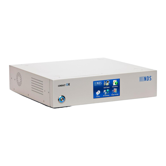
Page 9: Conductor Overview
ConductOR Overview The ConductOR has 4 fixed inputs as shown in Fixed Inputs table below. Up to 4 input modules and up to 4 output modules may be added. The drawing on page 3 shows location of the fixed input connectors and the input and output modules. -
Page 10: Tab
ConductOR to control a Radiance EndoVue display via its RS-232 port. The RJ-22’s pin out and a ConductOR to Radiance EndoVue cable wiring diagram are on page 53. The required serial commands document is described in the General Information section on the previous page. -
Page 11: Electrical Symbols
Electrical Symbols Equipotentiality: This symbol appears next to the ConductOR’s Potential Equalization Conductor . Power Switch: The power switch is push on / push off. When the switch is off the ring around the center portion is white. When the switch is on, the center portion is depressed and the ring is... -
Page 12: Input And Output Modules
Removable Input and Output Modules Input Modules: Two types of input modules are available: DVI-D and 3G-SDI. Notes: 1. The input modules, shown below, may be installed in any of the IN (see page 3) card slots in any combination and in any order. Up to four input modules may be installed. 2. -
Page 13: Module Removal And Installation
Module Removal and Installation The ConductOR must be turned off prior to installing or replacing input or output modules. Input Module Removal: Use a number 1 Phillips screwdriver to loosen, but not remove, the screws located on the upper left and lower right corners of the module’s mounting plate. -
Page 14: Typical System Configuration
Typical System Configuration System Control 3G-SDI, DVI or Fiber 3G-SDI, DVI or Fiber 3G-SDI, DVI or Fiber 3G-SDI, DVI or Fiber RS-232 Control This monitor displays the same information as monitor 3 USB or RS-232 Touch Screen DVI Output Control Displays the video from the selected streaming source. -
Page 15: Startup Screen
Startup Screen The Startup screen, shown below, appears as soon as power is applied to the ConductOR and is displayed until the ConductOR’s Power On Self Test (POST) finishes. The POST takes approximately 20 seconds to complete. After the POST finishes, the home screen is displayed. Home screen is shown on page 9. -
Page 16: Front Panel Operation
Select Inputs screen shown on the following page. Information Provides information about the ConductOR. The user may restore the ConductOR’s factory defaults or update the scalar firmware. Touch this icon to open the Information screen shown on page 14. IP Streaming This screen is associated with network operations and requires a network connection to be effective. -
Page 17: Select Inputs Screen
Note: As output 4 is slaved to output 3, a 3 will be shown on monitors 3 and 4. The PIP +, PIP - Swap and Disable PIP buttons are described on page 12. Touching the Keypad button opens the Keypad screen and allows access to the ConductOR features that are not frequently used. The Keypad buttons are described on page 13. -
Page 18: Primary And Secondary Input Screens
Primary and Secondary Input Screens DVI 2 Empty To select a primary input, touch the Change button on the Primary row. The illuminated button on the Primary Input screen is the current input. Select a Primary input by touching the button associated with that input. -
Page 19: Pip, Swap And Disable Pip Buttons
PIP, Swap and Disable PIP Buttons The PIP +, PIP -, Swap and Disable PIP buttons are located on the bottom row of the Select Inputs screen (page 10) and are effective only when a secondary input has been selected. Select a secondary input as described on the previous page. DVI 2 Split Screen with Overscan... -
Page 20: Keypad Screen
Touch fi or fl to select the menu or parameter you want work with. The Brightness / Contrast button usage is detailed on page 18. Touch the Go Back button to return to the Select Inputs screen. Changes made via the keypad are retained when the ConductOR‘s power is cycled. -
Page 21: Output Settings Screen
Information Screen Touch the Information icon on the Home screen (page 9) to display the Information screen. This screen displays general information about your ConductOR. See the screen shot below. Touching the Factory Defaults button restores the ConductOR’s factory settings. -
Page 22: Ip Streaming
The Remote IP address is set using the ConfigOR-G2 program (page 29). The Start button is used to establish an IP link between two ConductOR’s. The text in the Remote IP window turns green when the link is established. Note: The Start button is used... -
Page 23: Basic Operation
Select a primary input by touching the Select Inputs icon, shown below, on the Home screen (page 9) Touch the Identify button, a yellow number appears on each display connected to the ConductOR. The number clears after 5 seconds. Displays connected to OUT 3 and OUT 4 will show a 3. -
Page 24: Pip And Swap
PIP and Swap Selecting a secondary (PIP) image: Touch this button on the Secondary row of the Select Inputs screen (page 16) to open the Secondary Input screen, shown below. Touch the input button whose data you want to display as the secondary (PIP) image. -
Page 25: Image Adjustments
Image Adjustments Select the Keypad screen as described on page 13. Touch this button to identify the output you want to adjust. Note: The identify function requires that a monitor be connected to at least one of the four outputs. On the Select Display row touch the display icon that corresponds to the output whose brightness and / or contrast will be adjusted, connect a monitor to the output that will be adjusted. -
Page 26: On Screen Display Overview
On Screen Display Overview Select the Keypad screen as described on page 13. On the Select Display row touch the display icon for the output whose parameters will be adjusted. Touch the MENU button once to open the On Screen Display (OSD). -
Page 27: Display Setup
Display Setup SDI Picture Menu S-Video Picture Menu Composite Picture Menu Horizontal Position Moves the image to the left or right. Touch fi or fl to horizontally center the image. Note: This parameter is not available for SDI inputs. Vertical Position Moves the image up or down. -
Page 28: Vga / Sog Picture Menu
Select using fi or fl buttons. SmartSync™ / Alternative Modes On initialization NDS’ proprietary SmartSync technology examines the incoming signal and automatically displays the video image in its proper format. To run SmartSync select the SmartSync / Alternative Modes parameter and touch the fi button. -
Page 29: Dvi Picture Menu
DVI Picture Menu LAN Picture Menu Overscan (Video) This parameter is enabled when the input is video (camera) data. 0 = The image is displayed at a size that fills the screen without losing any video information. The image presented to the display may include black bars top and bottom or left and right. 1, 2, 3, 4, 5 or 6 = The image is linearly enlarged, while remaining centered, in incremental steps. -
Page 30: Color Menu
Color Menus Graphics Color Menu Video Color Menu Gamma (Graphic modes only) Press fi or fl to select a preset Gamma value, Video PACS Notes: Video is a color corrected Look Up Table (LUT) available with DVI, VGA and SOG. PACS is a DICOM-like* LUT available with DVI, VGA and SOG. -
Page 31: Setup Menu
The default position is in the lower left corner. Language The ConductOR currently supports English only. DPMS Enable Display Power Management System. This function is not supported on the ConductOR. Auto Source Select This function is not supported on the ConductOR. Menu Lock The menu may be locked via an external control program. -
Page 32: Tab 8 Utilities
They may not be used during clinical procedures. Place the supplied Integration Software and Users Manual CD (58E0017) in your PC’s CD or DVD drive and double click the My Computer icon. Double click the 58E0017 icon. Double click the ConductOR folder. Continued on the following page. -
Page 33: Streaming Video & Audio
Select the software to be installed and double click its folder. Double click the Setup icon. Follow the on screen instructions. Repeat steps 3 and 4 for each additional software package you want to install. E:\ConductOR ViewOR G2 ConfigOR-G2 ConductOR Demo E:\ConductOR\58D0013-B_View-OR G2... -
Page 34: Location To Location Network Connections
If surgeons or other clinical staff members need to consult with their colleagues at another location and each location has a ConductOR available. The ConductORs may be connected via your internal network or the Internet for the purpose of video and audio communication. Video transmitted from the ConductOR designated as ‘Transmit’... - Page 35 Connect an RS-232 cable from your PC to the ConductOR’s RS-232 IN connector. Continued on the following pages * A DHCP assigned IP address may change if the ConductOR is disconnected from the network and reconnected or if it is turned off.
-
Page 36: Location To Location Transmit Setup
Location to Location Transmit Setup Note: The IP addresses that appear in the screen shots on this and following pages are for illustration only. Launch the ConfigOR-G2 program, the program’s startup screen should look like the left screen shot below. A Not Connected message will be shown in its lower left corner Click the pull down arrow on the right side of the COM Port window and select the COM port to be used. - Page 37 Location to Location Receive Setup Move the RS-232 cable to the Receive unit’s RS-232 IN connector (page 30). Launch the ConfigOR-G2 program, described on the previous page. Select the COM port to be used, then click the Connect button. Click the Connect button, a successful connection will ‘gray out’ the Connect button, fill in the Address, Subnet Mask and Gateway windows.
-
Page 38: Location To Location Streaming
Location to Location Streaming Note: The following steps assume that you are continuing from the Software Setup section. Touch the IP Streaming icon on the Transmit unit’s Home screen (page 9). When the IP Streaming screen is displayed, select: On the Mode row, select Transmit by touching the Transmit button. On the Stream Source row select the Display (output) to be used as the streaming source. - Page 39 Touch the Start button. The legend on the button changes to Stop. “Connecting to….” screen is displayed. When the “Connected” screen is displayed, streaming has started. Continued on the next page.
- Page 40 The Transmit unit’s IP Streaming and the Receive unit’s screens while streaming is in progress are shown below. The Transmit unit’s Remote IP window holds the address of the Receive unit’s IP address. The Receive unit’s address changes to green when an connection is established. The Receive unit’s Remote IP window remains empty.
-
Page 41: Streaming Video
Streaming Video Note: The following steps assume that you are continuing from the previous page. Comment: In the Transmit Unit Setup section, Display 1 and the DVI-2 input are used for illustration. Transmit Unit Setup: Connect a signal source to the Transmit unit’s DVI-2 connector. - Page 42 Comment: In the Receive Unit Setup section, Display 1 is used for illustration. Receive Unit Setup: Connect the Receive unit’s OUT 1 (Connector Panel is shown on page 3) to a compatible display. On the Receive unit’s Home screen (page 9) touch the Select Inputs icon. On the Select Display row touch the Display 1 icon.
-
Page 43: Streaming Audio
Streaming Audio Use the setup described in the Streaming Video section (pages 27). Connect a microphone (blue line) to the AUDIO IN MIC connector of both units and a set of headphones (red line) to the AUDIO OUT connector of both units. Speak into the microphone connected to the Transmit unit and you should hear your voice in the headphones connected to the Receive unit. -
Page 44: Streaming From Conductor To A Pc
Streaming from ConductOR to a PC Overview: During a surgical procedure the surgeon performing the procedure may need to consult with one or more colleagues at other locations. If the colleagues have a PC, Internet connection and ViewOR available, they will be able to observe the procedure in real time and provide assistance as needed. -
Page 45: Viewor G2 Setup And Usage
ViewOR G2 Setup and Usage Preparing the ConductOR: Connect the ConductOR (unit) to your network then connect the network to your PC using Ethernet cables. Turn the PC and unit on. Connect a compatible signal source to the unit’s DVI 2 input. - Page 46 Settings in the following procedure are for illustration. Touch the IP Streaming icon on the Home screen (page 9) to access the IP Streaming screen. On the Mode row, touch the Transmit button. Select Display 1 on the Stream Source row. Select 720p on the Stream Resolution row.
-
Page 47: Configor Setup
ConfigOR Setup Launch the ConfigOR-G2 program (page 29), the program’s startup screen should look like the left screen shot below. A Not Connected message will be shown in its lower left corner Click the down pull arrow on the right side of the COM Port window and select the COM port to be used. -
Page 48: Using The Viewor G2 Program
Using the ViewOR G2 Program The ViewOR G2 program must be run on a PC, it is not currently compatible with Apple computers Double click the ViewOR G2 icon to launch the program. Click the fl button, the Open Media window is displayed. Click the Open Media window’s Network tab. - Page 49 The RTSP authentication window is displayed. In the User name window, type: root (all lower case). In the Password window, type: admin (all lower case). Click the OK button. A copy of the image on display 1 is displayed in the ViewOR G2 viewing area. Note: It takes up to 15 seconds before an image is displayed.
- Page 50 Click the Telephone Handset button to open a two way audio path. The button turns red and a Call Ringing message appears. Call Connected appears when the audio connection is established. Place the cursor over the Volume slider, hold the left mouse button down and set the volume to the desired level.
-
Page 51: User Configuration
User Configuration Connect your PC to the ConductOR via an RS-232 cable. Verify that both are powered on. Launch the ConfigOR-G2 program, click the Connect button and verify that Connected appears in the lower left corner. See example on page 23. -
Page 52: Demonstration Program
Demonstraton Program The included Demonstration program (NDS 58D0023) is intended for demonstration, installation and testing of the ConductOR. It may not be used in an OR while any clinical procedure is in progress. Setup: 1. Connect a straight through serial cable (NDS 35D0003 or equivalent) from the PC’s serial port to the RS-232 IN connector. - Page 53 When the program is communicating with the ConductOR, the green button will be illuminated. Display 1 will be the active display with a red ring surrounding it. One of the primary input buttons will be illuminated. A label will be added each of the four right primary and secondary inputs that has a corresponding input module installed.
- Page 54 Select OUT 1, 2 or 3 by clicking the Display 1, Display 2 or Display 3 icon, Display 4 Out 4 are selected when Display 3 is selected. The selected display icon will be surrounded by a red ring. A secondary input may be selected by clicking one of the Secondary Inputs buttons. A graphic showing the size of the secondary (PIP) window will appear in the active display.
-
Page 55: Troubleshooting And Test Section
Troubleshooting and Test Section Problem Possible Causes and Remedies Power switch does not Loose Power Cable: Verify that the power cable is fully inserted into the unit’s illuminate in the ON power connector. state Failed Fuse: See Fuse Replacement procedure on page 56. Wall Socket: Some wall sockets have on / off switches built in. - Page 56 2. From the front panel select IP Streaming the IP Address window should hold an IP address. 3. From a PC connected to the same network as the ConductOR, click the start button then select: All Programs > Accessories > Command Prompt.
-
Page 57: Serial Port Setup
Serial Port Setup Hardware Setup Turn the ConductOR on. Connect your PC to the ConductOR using a standard RS-232 (NDS P/N 35D0003 or equivalent) cable. Hyper Terminal Setup The table at the bottom of this page shows the serial port parameters. -
Page 58: Drawing And Dimensions
Drawing and Dimensions... -
Page 59: Video Connectors And Pin Outs
Video Connectors and Pin Outs DVI-I* Fiber Optic Digital and Analog . Clock DVI-I Supports digital and analog (RGBS / YPbPr). Analog data Blue appears on pin 8 and pins, C1 through C5. Green * Compliant with DVI 1.0 PIN# SIGNAL PIN# SIGNAL T.M.D.S. -
Page 60: Data Connectors And Pin Outs
Description Transmit Transmit Return +5 VDC Receive Data - Unused Unused Data + Receive Return Unused Ground Unused The USB port is used for external storage ConductOR Display Control Cable RS-232 cable for NDS Radiance or EndoVue display RJ-22 DB-9... -
Page 61: Dc Power Connectors And Pinouts
DC Power Connectors and Pin Outs Weidmuller BL 3.81/3 connector + 24 Chassis 24 Volt Extension Cables Use only copper wire for power wiring. Power extension cable must be constructed in accordance with applicable hospital and electrical codes. Cable should be constructed of SJT, SJTO, SJO, ST, SO, STO or equivalent flexible cord per US National Difference Clause 59.1DV. -
Page 62: Mm Audio Plug And Pin Out
Right (Ring) Ground (Sleeve) Fuse Replacement 1. Disconnect the power cord from the ConductOR. 2. Using a small screwdriver at point A, pry the Fuse Box out . 3. Replace the fuse with a Buss T5AL 250V or equivalent. 4. Slide the Fuse Box into its receptacle and press until it seats. -
Page 63: Tab 13 Specifications
-4 to +140 F (-20 to +60 Storage Humidity 5 to 85% RH Notes: 1. Specifications are subject to change without notice. Contact NDS for recent specifications. 2. User selectable. 3. Without a load connected to the ConductOR’s 24VDC output. -
Page 64: Video Inputs
Video and Graphics Inputs Connector Type Fixed Inputs S-video DIN-4 Composite BNC, 75 Ohm terminated VGA / Sync-On-Green (SOG) HD-15 DVI / RGBS / YPbPr DVI-I Input Modules DVI Input Module DVI -D SDI Input Module BNC, 75 Ohm terminated Output Modules DVI Output Module DVI-D... - Page 66 Corporate Headquarters Europe Asia Pacific 5750 Hellyer Avenue Nijverheidcentrum 28 Takanawa Kaneo Bldg., 6F San Jose, CA 95138 2761 JP Zevenhuizen (ZH) Asakusabashi 5-Chome, United States (USA) The Netherlands Minato-ku Tokyo 108-0074 Tel: 408 776 0085 Tel: +31 180 63 43 56 Japan Email: info@ndssi.nl Tel: + 81 3 5475 1835...
Need help?
Do you have a question about the ConductOR and is the answer not in the manual?
Questions and answers