
Related Manuals for adept technology SmartController EX


Summary of Contents for adept technology SmartController EX
- Page 1 Adept SmartController EX User's Guide Covers the SmartController EX Motion Controller and sDIO Module...
- Page 3 Adept SmartController EX User's Guide Covers the SmartController EX Motion Controller and sDIO Module P/N:11069-000 Rev.C March, 2013 5960 Inglewood Drive • Pleasanton, CA 94588 • USA • Phone 925.245.3400 • Fax 925.960.0452 Otto-Hahn-Strasse 23 • 44227 Dortmund • Germany • Phone +49.231.75.89.40 • Fax +49.231.75.89.450...
- Page 4 The information contained herein is the property of Adept Technology, Inc., and shall not be reproduced in whole or in part without prior written approval of Adept Technology, Inc. The information herein is subject to change without notice and should not be construed as a commitment by Adept Technology, Inc.
-
Page 5: Table Of Contents
Chapter 2: Installation 2.1 Controller Installation Before Unpacking Upon Unpacking Repacking for Relocation Space Around the Chassis Mounting the Adept SmartController EX Motion Controller Memory Card Connecting Power IEEE 1394 Cable Specifications 2.2 System Cable Installation Chapter 3: Operation 3.1 Connectors and Indicators 3.2 Front Panel... - Page 6 3.7 Belt Encoder Interface Chapter 4: Maintenance 4.1 Changing the Lamp in the Front Panel High-Power Indicator Chapter 5: Technical Specifications 5.1 Adept SmartController EX Motion Controller Dimensions 5.2 sDIO Module Dimensions 5.3 Adept Front Panel Dimensions 5.4 Adept T20 Pendant Dimensions Chapter 6: sDIO Module 6.1 Mounting the sDIO Module...
- Page 7 7.3 DeviceNet Port on the Controller Connecting DeviceNet Hardware to the Controller Configuring DeviceNet 7.4 DeviceNet Physical Layer and Media DeviceNet Connectors Termination of the DeviceNet Network Power Supply and the DeviceNet Bus Adept SmartController EX User’s Guide, Rev.C Page 7 of 96...
-
Page 9: Chapter 1: Introduction
Chapter 1: Introduction 1.1 Product Description The Adept SmartController EX motion controller is a member of Adept’s family of high-per- formance distributed motion controllers. The Adept SmartController EX motion controller is designed for use with Adept Python Linear Modules, Adept Cobra s-series robots, the Adept Viper line of six-axis robots, the Adept sMI6 Module for the SmartMotion product, Adept SmartServo kits, and Adept Quattro robots. -
Page 10: Dangers, Warnings, Cautions, And Notes In Manual
1.2 Dangers, Warnings, Cautions, and Notes in Manual There are six levels of special alert notation that may be used in Adept manuals. In descend- ing order of importance, they are: Adept SmartController EX User’s Guide, Rev.C Page 10 of 96... -
Page 11: Safety Precautions
Contact Adept if you are not sure of the suitability for your application. The user is responsible for providing safety barriers around the robot to prevent anyone from accidentally coming into contact with the robot when it is in motion. Adept SmartController EX User’s Guide, Rev.C Page 11 of 96... -
Page 12: What To Do In An Emergency Situation
4. Use the Description column to locate the document for your SmartController, and then click the corresponding Download ID number to access the Download Details page. 5. On the Download Details page, click Download to open or save the file. Adept SmartController EX User’s Guide, Rev.C Page 12 of 96... -
Page 13: How Can I Get Help
For further information about Adept Technology, Inc.: http://www.adept.com Related Manuals This manual covers the installation and maintenance of an Adept SmartController EX motion controller system, including the sDIO expansion module. There are additional manuals that cover programming the system, reconfiguring installed components, and adding other optional components. - Page 14 Chapter 1: Introduction To locate information on a specific topic, use the Document Library search engine on the ADL main page. Adept SmartController EX User’s Guide, Rev.C Page 14 of 96...
-
Page 15: Chapter 2: Installation
Retain all containers and packaging materials. These items may be needed in the future to set- tle a damage claim. Perform the following steps to unpack the Adept SmartController EX motion controller and Front Panel, optional Adept sDIO expansion module Expansion Module, and optional pend- ant. -
Page 16: Repacking For Relocation
Improper packaging for shipment will void your warranty. Space Around the Chassis When the Adept SmartController EX motion controller and/or sDIO expansion module is installed, you must allow 10 mm at the back of the unit and 13 mm on the sides of the unit for proper air cooling. - Page 17 14.2 TYP. 482.8 Figure 2-1. Rack-Mounting the Adept SmartController EX Motion Controller Panel-Mounting the Adept SmartController EX Motion Controller To panel-mount the controller, install two brackets on each side at the rear of the unit, as shown in the following figure. Use the screws from the accessories kit.
- Page 18 Figure 2-3. Table-Mounting the Adept SmartController EX Motion Controller Stack-Mounting Components To stack-mount the Adept SmartController EX Motion Controller and a compatible unit, such as an Adept SmartVision EX vision controller, install two brackets on each side of the units, as shown in the following figure.
-
Page 19: Memory Card
The SD card shipped with all systems is factory-configured and installed by Adept. The SD card stores the eV+ operating system, application programs, data files, and Adept licenses. Only the SD card supplied by Adept will work with the Adept SmartController EX motion con- troller. - Page 20 CAUTION: Do not remove the SD card when power is connected to the controller. Removing an SD Card To remove an SD card from a Adept SmartController EX motion controller: 1. Make sure that the controller is disconnected from its power source. 2. Locate the SD compartment (see the following figure).
-
Page 21: Connecting Power
Chapter 2: Installation Connecting Power The Adept SmartController EX motion controller and sDIO expansion module require filtered 24 VDC power. NOTE: Users must provide their own power supply. Make sure the power cables and power supply conform to the specifications that follow. - Page 22 NOTE: The power requirements for the user-supplied power supply will vary depending on the configuration of the Adept SmartController EX motion controller and connected devices. A mini- mum configuration of the controller, front panel, and pendant will require 2 A at 24 VDC. How- ever, a 24 V, 5 A power supply is recommended to allow for additional current draw from connected devices, such as external IEEE 1394 devices and digital I/O loads.
- Page 23 Chapter 2: Installation NOTE: The power switch on the Adept SmartController EX motion controller will shut down just the controller. The two connectors, XDC1 and XDC2, are always connected to each other, so a sec- ondary device will maintain power after the controller is shut down.
-
Page 24: Ieee 1394 Cable Specifications
DC polarities on the XDC connectors are reversed. IEEE 1394 Cable Specifications Adept supplies the IEEE 1394 cables to connect the Adept SmartController EX motion con- troller to other Adept devices in the system. If you need a cable of a different length than those... -
Page 25: System Cable Installation
2.2 System Cable Installation The Adept SmartController EX motion controller is used in many Adept systems, including Adept Python Linear Modules, Adept Cobra s-series robots, the Adept Viper line of six-axis robots, Adept Quattro robots, and the Adept sMI6 Module for the SmartMotion product. -
Page 27: Chapter 3: Operation
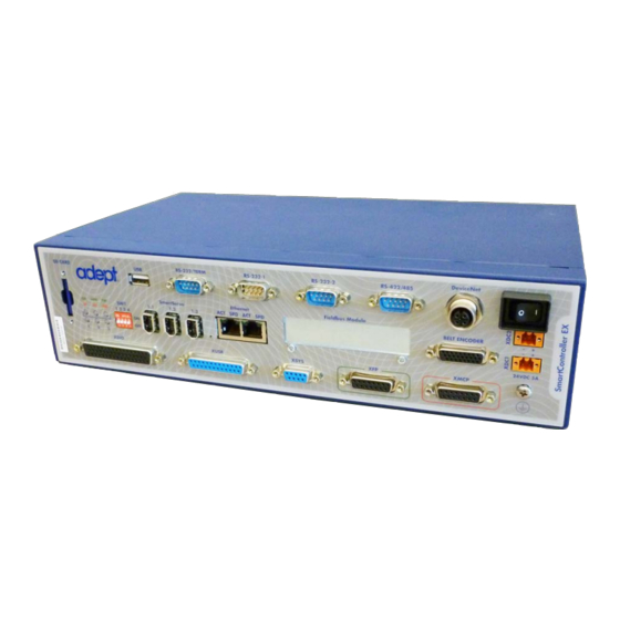
3.1 Connectors and Indicators Figure 3-1. SmartController EX Connectors and Indicators All of the connectors on the Adept SmartController EX motion controller use standard-density spacing, D-subminiature connectors. For customization purposes, the user needs to provide connectors of the appropriate gender and pin count, or use optional Adept cables. - Page 28 Connect software. Refer the the Adept ePLC Connect User's Guide, chapt- ger 3, for a description of those LEDs with ePLC Connect. The bottom three LEDs on the front of the Adept SmartController EX motion controller give the following information about the status of the main controller.
- Page 29 The digital outputs are short-circuit protected. This connector also supplies 24 VDC power for customer equipment. See Connecting User- Supplied Digital I/O Equipment on page 44 for more information. Adept SmartController EX User’s Guide, Rev.C Page 29 of 96...
- Page 30 E-Stop push-buttons and the Man- ual/Automatic switch. NOTE: The Adept SmartController EX motion controller ships with a terminator plug attached to the XUSR connector. The terminator plug must be installed in the absence of any user-supplied safety equipment used to close the E-Stop circuit.
-
Page 31: Front Panel
Manual mode initiates software restrictions on robot speed, commanding no more than 250 mm/sec as required by RIA and ISO standards. Please refer to your robot manual for further details. Adept SmartController EX User’s Guide, Rev.C Page 31 of 96... -
Page 32: Programming The E-Stop Delay
WARNING: Make sure that all cables are installed correctly and fully inserted and screwed down before applying power to the system. Failure to do this could cause unexpected robot motion. Also, a connector could be pulled out or dislodged unexpectedly. Adept SmartController EX User’s Guide, Rev.C Page 32 of 96... -
Page 33: Configuring The Smartcontroller
Start-up Procedure. NOTE: You will have to restart the PC after installing the Adept ACE software. 3.4 Configuring the SmartController Configuring Serial Ports The Adept SmartController EX motion controller has four serial I/O ports: RS-232/Term RS-422/485 RS-232-1 RS-232-2 See Connectors and Indicators on page 27 for the connector locations. -
Page 34: Rs-232 Connectors
The pin assignments are the same for all three connectors and are shown in the following table. Table 3-3. RS-232 Connector Pin Assignments Pin RS-232-1 RS-232-2 RS-232/Term Signal Type Signal Type Reserved Input Input Output Output Reserved Adept SmartController EX User’s Guide, Rev.C Page 34 of 96... -
Page 35: Rs-422/485 Connector
RS-422 is a point-to-point protocol for connecting to a single destination. This port can also be configured as a multidrop port (RS-485). Table 3-5. RS-422/485 Connector Pin Assignments Signal Type RXD+ Input TXD+ Output TXD- Output Ground RXD– Input Adept SmartController EX User’s Guide, Rev.C Page 35 of 96... -
Page 36: Connecting User-Supplied Safety And Power-Control Equipment
E-Stops are not tripped 9, 22 Manual/Automatic indication CH 1 Contacts are closed in Automatic mode 10, 23 Manual/Automatic indication CH 2 Contacts are closed in Automatic mode Adept SmartController EX User’s Guide, Rev.C Page 36 of 96... - Page 37 NOTE: The system was evaluated by Underwriters Laboratory with an Adept Front Panel. If you provide a substitute Front Panel, this could void UL compliance. Adept SmartController EX User’s Guide, Rev.C Page 37 of 96...
- Page 38 No Connection ESTOPSRC 24 V Output to Slave ESTOP NOTE: The XSYS connector is used to link the E-Stop system to Adept robots. It is not intended for customer connections. Adept SmartController EX User’s Guide, Rev.C Page 38 of 96...
- Page 39 Chapter 3: Operation The following figure shows an E-Stop diagram for the Adept SmartController EX motion con- troller. See Introduction on page 9 for a description of the functionality of this circuit. Internal Connections User Supplied Connections 24 V Channel 1...
-
Page 40: Emergency Stop Circuits
Figure 3-5. Front Panel Schematic Emergency Stop Circuits The Adept SmartController EX motion controller provides connections for Emergency Stop (E- Stop) circuits on the XUSR and XFP connectors. This gives the controller system the ability to duplicate E-Stop functionality from a remote location using voltage-free contacts. See the figure CAT-3 E-Stop Circuit on XUSR and XFP Connectors on page 39. - Page 41 Automatic mode, the robot defaults to Manual mode operation when power is re- enabled. In muted mode, the gate can be left open for personnel to work in the robot cell. How- ever, safety is maintained because of the speed restriction. Adept SmartController EX User’s Guide, Rev.C Page 41 of 96...
-
Page 42: Remote Manual Mode
40 VDC or 30 VAC at a maximum of 1 A. User High Power On Indication In the Adept SmartController EX motion controller, eV+ controls a normally-open relay contact on the XDIO connector (pins 45, 46, see the table XDIO Digital I/O Connector Pin Assignments on page 48), that will close when high power has been enabled. -
Page 43: High Power On/Off Lamp
Wire Size: must be larger than 26 AWG. Connectors: must be 15-pin, standard D-sub male and female. Maximum cable length is 10 meters. Adept SmartController EX User’s Guide, Rev.C Page 43 of 96... -
Page 44: Remote Pendant Usage
See Adept DeviceNet on page 85 for details. XDIO Connector The XDIO connector on the Adept SmartController EX motion controller is a 50-pin, standard density D-Sub female connector (see SmartController EX Connectors and Indicators on page 27 for location). There are 12 inputs and 8 outputs, each optically isolated from the circuitry of the controller. - Page 45 2 shows inputs (1005 to 1008) with a positive common, and example 3 shows inputs (1009 to 1012) with an independent power supply (no common). NOTE: These are examples. Either method can be used on any channel. Adept SmartController EX User’s Guide, Rev.C Page 45 of 96...
- Page 46 I/O channel usage accordingly. In addition to functioning as normal input signals, all input signals can have the following special uses: Fast DIO eV+ Interrupt Events (INT.EVENT) Robot and Encoder Position Latch Adept SmartController EX User’s Guide, Rev.C Page 46 of 96...
- Page 47 NOTE: These are examples. Either method can be used, in any combination, on any channel. Also, an external customer-provided power supply could have been provided instead of the power pro- vided on the XDIO connector. Adept SmartController EX User’s Guide, Rev.C Page 47 of 96...
- Page 48 1003 return Output 0003+ Output 0003– Input 1004 1004 return Output 0004+ Output 0004– Input 1005 1005 return Output 0005+ Output 0005– Input 1006 1006 return Output 0006+ Output 0006– Adept SmartController EX User’s Guide, Rev.C Page 48 of 96...
-
Page 49: Belt Encoder Interface
Controller CX. The 15-pin adapter is Adept P/N: 09443-000. Each 15-pin adapter provides two M12 connections. All encoder inputs for the Adept SmartController EX motion controller use a scheme similar to an RS-422 differential receiver based on industry standard 75175 integrated circuits. The dif- Adept SmartController EX User’s Guide, Rev.C... - Page 50 See the Adept ACE User's Guide for more information on setting up and programming a con- veyor-tracking application. NOTE: Conveyor tracking requires the eV+ Extensions License, which can be obtained from Adept. Adept SmartController EX User’s Guide, Rev.C Page 50 of 96...
- Page 51 ENC2_A- ENC1_Z+ ENC3_A+ ENC1_Z- ENC3_A- ENC2_Z+ ENC4_A+ ENC2_Z- ENC4_A- ENC3_Z+ ENC1_B+ ENC3_Z- ENC1_B- ENC4_Z+ ENC2_B+ ENC4_Z- BELT ENCODER Pin 9 Pin 1 Pin 18 Pin 10 Pin 26 Pin 19 Adept SmartController EX User’s Guide, Rev.C Page 51 of 96...
- Page 52 Encoder power output: 5 V at 800 mA max. Enc. Pwr (1 A current limit) Enc. Gnd Encoder Channel 2 Shield Encoder – A – B – I – Figure 3-8. Belt Encoder Typical Input Circuit Adept SmartController EX User’s Guide, Rev.C Page 52 of 96...
- Page 53 Chapter 3: Operation Figure 3-9. Belt Encoder Connector Adept SmartController EX User’s Guide, Rev.C Page 53 of 96...
-
Page 55: Chapter 4: Maintenance
WARNING: The procedures and replacement of parts mentioned in this section should be performed only by trained, authorized personnel. The access covers on the Adept SmartController EX motion controller are not interlocked – turn off and disconnect power if covers have to be removed. - Page 56 Wires between LED and body of Front Panel. Be careful when separating front cover from body to avoid High Power On/Off damaging the wires. Lamp Body Figure 4-1. Lamp Body Contact Alignment Adept SmartController EX User’s Guide, Rev.C Page 56 of 96...
-
Page 57: Chapter 5: Technical Specifications
Chapter 5: Technical Specifications This chapter shows the dimensions of the Adept SmartController EX motion controller, sDIO expansion module, Adept Front Panel, and T20 pendant. 5.1 Adept SmartController EX Motion Controller Dimensions NOTE: The dimensions for the CS and CX SmartController motion controllers were the same as these. -
Page 58: Sdio Module Dimensions
Chapter 5: Technical Specifications 5.2 sDIO Module Dimensions 328.9 IEEE-1394 *S/N 3563-XXXXX* XDC1 XDC2 LINK 41.6 0.5A 186.5 Ground Connection Point Figure 5-2. sDIO Module Dimensions Adept SmartController EX User’s Guide, Rev.C Page 58 of 96... -
Page 59: Adept Front Panel Dimensions
Chapter 5: Technical Specifications 5.3 Adept Front Panel Dimensions 152.4 38.7 STOP 55.9 88.9 16.5 129.5 13.1 4X M4 x 18 MM 76.2 139.7 Figure 5-3. Adept Front Panel Dimensions Adept SmartController EX User’s Guide, Rev.C Page 59 of 96... -
Page 60: Adept T20 Pendant Dimensions
Chapter 5: Technical Specifications 5.4 Adept T20 Pendant Dimensions Figure 5-4. T20 Pendant Dimensions Adept SmartController EX User’s Guide, Rev.C Page 60 of 96... -
Page 61: Chapter 6: Sdio Module
To rack-mount the sDIO module in a standard 19-inch equipment rack, you must first install the mounting brackets on each side of the unit, as shown in the following figure. NOTE: These brackets must be ordered separately. They do not come with the sDIO module. Adept SmartController EX User’s Guide, Rev.C Page 61 of 96... - Page 62 Chapter 6: sDIO Module 190.0 2X M3 x 6MM 2X 40356-00003 BOTH SIDES R 3.6 16.0 43.9 31.8 14.0 14.2 462.0 482.8 TYP. Figure 6-2. Rack-Mounting the sDIO Module Adept SmartController EX User’s Guide, Rev.C Page 62 of 96...
-
Page 63: Panel-Mounting The Sdio Module
To table-mount the sDIO module, install two brackets on each side near the bottom of the unit, as shown in the following figure. NOTE: These brackets must be ordered separately. They do not come with the sDIO module. Adept SmartController EX User’s Guide, Rev.C Page 63 of 96... -
Page 64: Stack-Mounting The Sdio Module
4. Connect an IEEE 1394 cable from one of the SmartServo ports on the controller to one of the IEEE 1394 ports on the sDIO module. Continue to daisy-chain IEEE 1394 cables from each sDIO module to the next. Adept SmartController EX User’s Guide, Rev.C Page 64 of 96... -
Page 65: Sdio Module Connectors And Indicators
7. Two 24 VDC connectors: Connect power from the unused XDC connector on the Smart- Controller to the XDC1 connector on the sDIO module (see Connecting Power on page 21 for power specifications). Adept SmartController EX User’s Guide, Rev.C Page 65 of 96... -
Page 66: Configuring An Sdio Module
Chapter 6: sDIO Module 6.4 Configuring an sDIO Module The Adept SmartController EX motion controller is preconfigured to support two sDIO mod- ules. Its configuration is based upon an I/O block assignment method that uses 4 bytes per block and 8 signals per byte, so each byte within a block represents a range of eight Input or Output signals. - Page 67 Item Values field. Statement id is either the input block or output block for Adept 1394 I/Os 5. When you have configured all of the I/O, click Done. Adept SmartController EX User’s Guide, Rev.C Page 67 of 96...
- Page 68 Chapter 6: sDIO Module Figure 6-6. Controller Configuration Screen, Digital Input Adept SmartController EX User’s Guide, Rev.C Page 68 of 96...
- Page 69 Byte 4 Internal IO IO Blox 1 IO Blox 2 IO Blox 3 IO Blox 4 (0137-0144) (3001-3004) (0145-0152) (0153-0160) (0161-0168) (0169-0176) Figure 6-7. Input/Output Block Configuration in Dual-robot Systems Adept SmartController EX User’s Guide, Rev.C Page 69 of 96...
- Page 70 Note: for sDIO #3 and #4 (and beyond), the values shown are recommended, but must be configured, so that the system will support those modules. Figure 6-8. Input/Output Block Configuration for Optional sDIO Modules Adept SmartController EX User’s Guide, Rev.C Page 70 of 96...
-
Page 71: Installing Multiple Sdio Modules
16. The second sDIO module uses block 17. Additional sDIO modules need to be configured. Refer to Modifying the Default sDIO Configuration on page 66, and the values in the figure Input/Output Block Configuration for Optional sDIO Modules on page 70. Adept SmartController EX User’s Guide, Rev.C Page 71 of 96... -
Page 72: Sdio Digital I/O Signals
1 ms scan cycle/ 1 ms max response time Turn off response time (hardware) 5 µsec maximum Software scan rate/response time 1 ms scan cycle/ 1 ms max response time Adept SmartController EX User’s Guide, Rev.C Page 72 of 96... - Page 73 Supply Group 2 Retur n Input Group 3 Adept Digital Input Signals 1049 – 1056 Cable (optional) Input Group 4 Signals 1057 – 1064 Figure 6-10. Typical sDIO Input Wiring Adept SmartController EX User’s Guide, Rev.C Page 73 of 96...
-
Page 74: Sdio Outputs
An extended output (for example, a SIGNAL in the range of 33 to 64) has been turned on by an eV+ command. An activated output has a thermal-overload problem, usually due to a short in the user’s wiring from the output pin to the user’s ground. Adept SmartController EX User’s Guide, Rev.C Page 74 of 96... - Page 75 The ground connection should connect to the power supply directly, not the ground con- nection of the load. This will isolate the board from any voltage drop across the ground return for the load. Adept SmartController EX User’s Guide, Rev.C Page 75 of 96...
- Page 76 CAUTION: The above specs. apply only to the output channels on the sDIO module. See the table DIO Output Specifications (XDIO connector) on page 47 for specs. on the XDIO connectors’ digital output channels. Adept SmartController EX User’s Guide, Rev.C Page 76 of 96...
-
Page 77: Optional Dio Cables
The optional digital input cables can be connected to either X3 or X4. Make sure to clearly label the cables once you have completed your installation so that the cables do not get swapped by mistake. See the warning that follows. Adept SmartController EX User’s Guide, Rev.C Page 77 of 96... - Page 78 1 return blue/red X3–26 group 1 return red/green X3–10 1041 green/black X3–1 1042 black X3–11 1043 orange/black X3–2 1044 white X3–12 1045 blue/black X3–3 1046 X3–13 1047 black/white X3–4 1048 green Adept SmartController EX User’s Guide, Rev.C Page 78 of 96...
- Page 79 Chapter 6: sDIO Module Signal Signal Wire Number Group Name Color X3–19 group 2 return white/red X3–20 group 2 return orange/red X3 26-pin female input connector on sDIO module Adept SmartController EX User’s Guide, Rev.C Page 79 of 96...
- Page 80 X4–12 1061 blue/black X4–3 1062 X4–13 1063 black/white X4–4 1064 green X4–19 group 4 return white/red X4–20 group 4 return orange/red X4 26-pin female input connector on sDIO module Adept SmartController EX User’s Guide, Rev.C Page 80 of 96...
- Page 81 X1–7 0041 white/black X1–6 0042 blue X1–5 0043 orange X1–4 0044 green X1–3 0045 X1–2 0046 white X1–1 0047 black X1–16 0048 blue/white X1–17 power black/red X1–18 power white/red Adept SmartController EX User’s Guide, Rev.C Page 81 of 96...
- Page 82 X2–13 0052 black/white X2–12 0053 blue/black X2–11 0054 orange/black X2–10 0055 green/black X2–9 0056 red/black X2–25 power orange/green X2–26 power black/white/red X2–38 power orange/black/green X2–39 power blue/white/orange X2–40 power black/white/orange Adept SmartController EX User’s Guide, Rev.C Page 82 of 96...
- Page 83 X2–33 power black/red/green X2–34 power white/red/green X2–35 power red/black/green X2–36 power green/black/orange X2–21 group 4 return blue/red X2–22 group 4 test red/green X2 44-pin female output connector on sDIO module Adept SmartController EX User’s Guide, Rev.C Page 83 of 96...
-
Page 85: Chapter 7: Adept Devicenet
I/O interfaces. 7.1 DeviceNet Specifications Adept Technology is a member of the Open DeviceNet Vendor Association (ODVA), which is independently run and operated and not directly associated with any one company. The ODVA controls DeviceNet technical specifications with help from Special Interest Groups (SIGs). -
Page 86: Limitations Of The Adept Devicenet Scanner
Message of the possible message types. 7.3 DeviceNet Port on the Controller The DeviceNet port on the Adept SmartController EX Motion Controller has the following con- figuration: Micro-style 12 mm thread DIN connector (female). See the following table for pin assignments. -
Page 87: Configuring Devicenet
91 Configuring DeviceNet The Adept SmartController EX motion controller has a default configuration such that, if you plug in a DeviceNet module configured with MAC_ID 1 and a baud rate of 125 kbps, the first 64 inputs and 64 outputs will automatically be mapped as signals 1289 to 1352 and 257 to 320, respectively. - Page 88 Adept ACE Configuration Tools. Those changes are not active until you reboot the Adept SmartController EX motion controller. The power distribution on the network/bus does not need to be in one place. The distribution of power supplies needs to be well planned because there are certain constraints on the power supply.
- Page 89 (328 ft) Maximum Drop Length (20 ft) (20 ft) (20 ft) Cumulative Drop Length 156 m 78 m 39 m (512 ft) (256 ft) (128 ft) Figure 7-2. DeviceNet Thick Cable Adept SmartController EX User’s Guide, Rev.C Page 89 of 96...
-
Page 90: Devicenet Connectors
Uses wires attached directly to screw terminals Sealed mini-style Attaches to taps and thick or thin cable Sealed micro-style Attaches to thin cable only – has a reduced current rat- Adept SmartController EX User’s Guide, Rev.C Page 90 of 96... -
Page 91: Termination Of The Devicenet Network
Provide over-current protection for each segment of your DeviceNet cable installation. NOTE: Adept does not supply the 24 V operating voltage for the DeviceNet bus on the Smart- Controller or any other Adept component. Adept SmartController EX User’s Guide, Rev.C Page 91 of 96... - Page 92 This calculation applies to the sum of the currents of all the nodes on the selected drop line. The length (l) is not the cumulative length of the drop line; it is the maximum distance from any node on the drop line to the trunk line. Adept SmartController EX User’s Guide, Rev.C Page 92 of 96...
- Page 93 It is important to note that voltage differences between the V– and V+ conductors need to be between 11 V and 25 V. The common-mode voltage between any two places on the V– wire must not exceed 5 V. Figure 7-6. DeviceNet Connector Pinouts Adept SmartController EX User’s Guide, Rev.C Page 93 of 96...
- Page 96 5960 Inglew ood D riv e Pleasanton, C A 94588 925 · 245 · 3400 P/N:11069-000 Rev.C...
Need help?
Do you have a question about the SmartController EX and is the answer not in the manual?
Questions and answers