
Related Manuals for B+K precision 4075B


Summary of Contents for B+K precision 4075B
- Page 1 Model: 4075B, 4076B, 4077B, 4078B, 4079B, 4080B Arbitrary/Function Waveform Generator USER MANUAL 1.800.544.2843 www.calcert.com sales@calcert.com...
- Page 2 Safety Summary The following safety precautions apply to both operating and maintenance personnel and must be followed during all phases of operation, service, and repair of this instrument. Before applying power to this instrument: Read and understand the safety and operational information in this manual. ...
- Page 3 Do not use this instrument in an electrical environment with a higher category rating than what is specified in this manual for this instrument. You must ensure that each accessory you use with this instrument has a category rating equal to or higher than the instrument's category rating to maintain the instrument's category rating.
- Page 4 particulates. The instrument is designed to be used in office-type indoor environments. Do not operate the instrument In the presence of noxious, corrosive, or flammable fumes, gases, vapors, chemicals, or finely- divided particulates. In relative humidity conditions outside the instrument's specifications. ...
- Page 5 Do not clean the instrument, its switches, or its terminals with contact cleaners, abrasives, lubricants, solvents, acids/bases, or other such chemicals. Clean the instrument only with a clean dry lint-free cloth or as instructed in this manual. Not for critical applications This instrument is not authorized for use in contact with the human body or for use as a component in a life-support device or system.
- Page 6 specified fuses will void the warranty. Servicing Do not substitute parts that are not approved by B&K Precision or modify this instrument. Return the instrument to B&K Precision for service and repair to ensure that safety and performance features are maintained.
-
Page 7: Compliance Statements
Compliance Statements Disposal of Old Electrical & Electronic Equipment (Applicable in the European Union and other European countries with separate collection systems) This product is subject to Directive 2002/96/EC of the European Parliament and the Council of the European Union on waste electrical and electronic equipment (WEEE), and in jurisdictions adopting that Directive, is marked as being put on the market after August 13, 2005, and should not be disposed of as unsorted municipal waste. - Page 8 CE Declaration of Conformity This instrument meets the requirements of 2006/95/EC Low Voltage Directive and 2004/108/EC Electromagnetic Compatibility Directive with the following standards. Low Voltage Directive EN61010-1: 2001 EMC Directive EN 61000-3-2: 2006 EN 61000-3-3: 1995+A1: 2001+A2: 2005 EN 61000-4-2 / -3 / -4 / -5 / -6 / -11 EN 61326-1: 2006 1.800.544.2843 www.calcert.com...
-
Page 9: Safety Symbols
Safety Symbols Refer to the user manual for warning information to avoid hazard or personal injury and prevent damage to instrument. Electric Shock hazard Alternating current (AC) Chassis (earth ground) symbol. Ground terminal On (Power). This is the In position of the power switch when instrument is ON. -
Page 10: Table Of Contents
Contents Safety Summary ....................i Compliance Statements ......................vi Safety Symbols ........................viii General Information ................1 Product Overview ......................1 Package Contents ......................1 Front Panel Overview ....................2 Front Panel Description ....................2 Rear Panel Overview ....................3 Rear Panel Description .................... - Page 11 Cursor Movement Keys ....................26 Rotary Input Knob ...................... 26 Power-On Settings ...................... 26 Memory ........................27 Displaying Errors ......................28 Creating an Arbitrary Waveform ................29 Entering Individual Data Points .................. 29 Creating a Complex Arbitrary Waveform ..............30 Setting the Frequency ....................
- Page 12 General Command Structure ..................38 SCPI Command Structure ................... 41 4.11 Status Reporting ......................43 The Status Byte ......................43 Service Request Enabling .................... 43 Standard Event Status Register .................. 43 The Error Queue ......................44 Error Codes ......................... 44 4.12 Common Commands ....................
- Page 13 :SYSTem Subsystem ..................... 90 4.16 Block Transfer (GPIB only) ..................92 4.17 GPIB Communication Protocol ................... 94 General ........................94 Responses to IEEE-488.1 Interface Messages ............94 IEEE 488.2 Interface Function Subsets ................ 97 Troubleshooting Guide ..............98 Specifications ..................99 SERVICE INFORMATION ................
-
Page 14: General Information
Report any damage to the shipping agent immediately. Save the original packing carton for possible future reshipment. Every instrument is shipped with the following contents: 1 x 4075B, 4076B, 4077B, 4078B, 4079B, or 4080B waveform generator 1 x Full instruction manual on CD ... -
Page 15: Front Panel Overview
1.3 Front Panel Overview (For Models 4075B, 4076B, and 4077B) Figure 1.1 – Front Panel Overview Front Panel Description Power On/Off Switch Function Keys (F1-F5) UTILITY Key CHANNEL Key (4078B, 4079B, and 4080B only) ENTER Key Channel Output BNC (50 Ω) and Enable... -
Page 16: Rear Panel Overview
1.4 Rear Panel Overview Figure 1.2 – Rear Panel Overview Rear Panel Description Modulation Input BNC External Trigger Input BNC Sync Output BNC Marker Output BNC 10 MHz Reference Output BNC 10 MHz Reference Input BNC USBTMC interface Earth Ground AC Power Connector and Fuse Box Rear Cooling Fan GPIB Port (4076B, 4077B, 4079B, and 4080B only) -
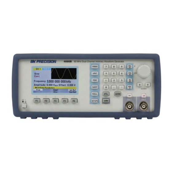
Page 17: Display Overview
1.5 Display Overview Figure 1.3 – Display Overview Display Description Wave Type Trigger Mode Frequency Menu Parameters Values Menu Options Menu Title General Waveform Display Channel Selection Indicator 2 Getting Started Before connecting and powering up the instrument, please review and go through the instructions in this chapter. -
Page 18: Input Power Requirements
2.1 Input Power Requirements Input Power The instrument has a universal AC input that accepts line voltage and frequency input within: 100 – 240 V (+/- 10%), 50 – 60 Hz (+/- 5%) Before connecting to an AC outlet or external power source, be sure that the power switch is in the OFF position and verify that the AC power cord, including the extension line, is compatible with the rated voltage/current and that there is sufficient circuit capacity for the power supply. -
Page 19: Impedance Matching
Impedance Matching If the waveform generator is driving a high impedance, such as a 1 MΩ input impedance (paralleled by a stated capacitance) of an oscilloscope vertical input, connect the transmission line to a 50 Ω attenuator, a 50 Ω termination and to the oscilloscope input. The attenuator isolates the input capacitance of the device and terminates the waveform generator properly. -
Page 20: Operating Instructions
5. Press the Ampl option in the menu and use the rotary knob or the numeric keypad to change the amplitude. Observe the changes on the oscilloscope display. 6. Press the Offset option in the menu and use the rotary knob or the numeric keypad to change the DC offset. - Page 21 o ADRS o DATA o PREV LINE o FROM o TO o EXEC NO YES PREV o PREV PREDEF o TYPE (Predefined Waveform Type) o FROM | DATA o LENG o SCALE (In %) o EXEC ...
- Page 22 PREV PREV o PROT FROM TO ALL ON | OFF PREV o SHOW WAVE o PREV PREV PREV MODE o CONT o TRIG MAN (Manual Trigger) INT (Internal Trigger Rate) ...
-
Page 23: Parameter Key
SHAPE (AM Modulation Shape) MOD FREQ (AM Modulation Frequency) EXT | INT (External or Internal Modulation) o FM (Not available in PULSE and ARB mode) ON | OFF DEV (FM Deviation Frequency) SHAPE (FM Modulation Shape) ... - Page 24 - (Rate) Selects and displays the Point Rate (for Arbitrary Waveform only). The Rate parameter governs the rate at which waveform points are executed, and thus the frequency of the waveform output. When you set this parameter, the waveform generator will keep that execution rate for all waveform lengths until it is changed. F3: Ampl/Ofst - Selects the Amplitude or the Offset parameters.
-
Page 25: Waveform Key
-4.5 V 9 Vp-p -4095 4 Vp-p -8191 -2 V F4: Units - Selects the amplitude units: peak-to-peak, RMS or dBm (sine waves only). Note: This option is shown when Ampl is selected. F5: 50 OHM/HI-Z - Selects the amplitude voltage value based on the two different impedance termination (i.e. - Page 26 Figure 3.4 - Arbitrary Menu F1: Start - Selects the starting address of the arbitrary waveform. F2: Length - Selects the length of the arbitrary waveform. Use the START and LENGTH menu selection to mark a selection of the waveform memory that will be executed.
- Page 27 Start Address Markers Length Arbitrary waveform from front panel channel output 5 V TTL signal output from rear Marker Out connector F4: Edit - Refer to the Arbitrary EDIT Menu section below for details. F5: Prev - Back to previous menu. Note: Changing one of the arbitrary parameters as start and length causes an update of the output waveform to the new parameters.
- Page 28 The data value governs the output amplitude of that point of the waveform, scaled to the instrument output amplitude. Therefore, a value of 8191 corresponds to positive peak amplitude, 0 corresponds to the waveform offset, and -8191 corresponds to the negative peak amplitude. The following menu displayed: Figure 3.7 - Edit Menu F1: Point...
- Page 29 Figure 3.9 - Predefine Waveform Menu F1: Type - Selects the waveform Sine, Triangle, Square, Noise, Ramp up, Ramp down, exponential up, exponential down, Sin(x)/x, and Gaussian distribution. If Noise function is selected, a submenu is displayed when F5: EXEC is pressed to allow adding the noise to an available waveform or to generate it as a new noise waveform.
- Page 30 Figure 3.10 - Scale Menu F5: Exec - Prompts you to confirm whether to execute the selected predefined waveform. Press NO to abort executing the predefined waveform; press YES to execute the predefined waveform. On the NOISE function a menu of ADD and NEW is prompted to select a new noise waveform or to add noise to the existing waveform.
-
Page 31: Pulse Menu
Protect Function - Protects (makes read-only) a section of waveform memory. Note: Only one segment of waveform memory can be protected at a time. F1: From - Selects the address of the first point to protect. F2: To - Selects the address of the last point to protect. F3: All - Clears the whole waveform memory. - Page 32 Figure 3.12 - Mode Menu F1: Cont - (Continuous) - Selects continuous output. F2: Trig - (Triggered) - Triggers one output cycle of the selected waveform for each trigger event. F3: Gate - (Gate) - Triggers output cycles as long as the trigger source asserts the gate signal. F4: Burst - (Burst) - Triggers output N output cycles for each trigger event, where N ranges from 2 to 999999.
-
Page 33: Sweep Key
Figure 3.14 - Trigger Menu F1: Man - Selects manual as the trigger source. To trigger the waveform generator, press this MAN TRIG again. F2: Int - (Internal) Selects the internal trigger generator as the trigger source. Change the internal trigger rate displayed with the rotary input knob. F3: Ext - (External) Selects the external trigger signal as the trigger source. -
Page 34: Modulation Key
F2: Start - Defines the Sweep Start frequency. F3: Stop - Defines the Sweep Stop frequency. F4: Rate - Defines the Sweep Rate. F5: Lin/Log - Selects Linear or Logarithmic Sweep. How to Set up Sweep in Different Modes By default, turning ON the sweep function will automatically set to a continuous (Cont) sweep. In order to change to other modes of sweep, do the following: 1. - Page 35 Figure 3.17 - AM Menu F1: ON/OFF - Turns the modulation ON or OFF. F2: % - Defines the AM modulation depth. F3: Shape - Defines the modulation shape between Sine, Triangle or Square. F4: Mod/Freq - Selects the modulation frequency, from 0.01 Hz to 20.00 KHz. F5: Ext/Int - Selects and enables the external modulation by an external signal applied to the Modulation In connector.
-
Page 36: Setups Key
Figure 3.19 - FSK Menu F1: ON/OFF - Turns the modulation ON or OFF. F2: F-LO - Defines the low frequency of the FSK. F3: F-HI - Defines the high frequency of the FSK. F4: Rate - Selects the rate of the alternating between the low and high frequencies. - Page 37 F1: Recall - Recalls a previously stored front-panel setup from the selected storage location. Change the storage location number by using the rotary input knob. Valid storage location numbers are from 0 to 49. Location 0 is a read-only buffer that contains the power-on settings listed in Table 3.3.
-
Page 38: Utility Key
8 full-length waveforms can be saved per channel. The saving is performed only on the waveform segment that is defined by the Start and Length parameters defined in the ARB menu. Note: Storing a waveform generator setup does not store waveform memory data. The STORE and RECALL function can be used as a tool to store and locate many arbitrary waveforms. -
Page 39: On Key
Figure 3.23 - Serial Number Information 3.2 ON Key Use this key to control the main output signal. When the output is active, the On button is illuminated by the built-in LED. 3.3 Cursor Movement Keys Use these keys to move the cursor (when visible) either left or right. They are used in conjunction with the rotary input knob to set the step size of the rotary input knob. -
Page 40: Memory
The waveform generator has two types of memory that can be stored and recalled: - Waveform Memory (8 waveforms per channel) - Setup Memory (0-49 buffer storage locations) Up to 8 full waveforms can be stored, each with up to the maximum waveform memory points available per channel. 4075B 4078B 4076B 4079B 4077B... -
Page 41: Displaying Errors
1. First, create or load 16,777,216 waveform data points into arbitrary waveform memory. For more information, please see the Creating an Arbitrary Waveform section. 2. Save all 16,777,216 points into ARB Wave 1 using the “Save ARB” key in the SETUPS menu. 3. -
Page 42: Creating An Arbitrary Waveform
Trig rate short Internal trigger rate too short for wave/burst. Empty location Attempt to restore nonexistent setting. SCALE too high Attempt to set scale too high for current dot value Protected RAM Attempt to write to protected RAM range. RAM error Error in testing RAM. -
Page 43: Creating A Complex Arbitrary Waveform
Creating a Complex Arbitrary Waveform To create a complex arbitrary waveform: Load a predefined sine waveform Load a scaled sine waveform at the positive peak of the first sine wave Draw a straight line between two data points in the waveform ... - Page 44 F3: YES Step 2: Load a 5% scaled, 100-point predefined F3: PREDEF waveform into waveform memory starting at F1: TYPE address 200. SINE F2: FROM F3: LENG F4: SCAL F5: EXEC F3: YES Step 3: Draw a line between address 251 (the F2: LINE highest point of the sine wave) and address 501 F1: FROM...
-
Page 45: Setting The Frequency
Figure 3.24 - Steps to set up an Arbitrary Waveform Setting the Frequency The arbitrary waveform frequency is a function of the number of data points used to run the waveform (the length parameter in the ARB menu) and the waveform execution point rate. The waveform execution point rate is the execution time between each point in the waveform. -
Page 46: Setting The Amplitude
Setting the Amplitude The following equation represents the relative output amplitude voltage relationship between the front-panel amplitude peak-to-peak setting and the data point values in waveform memory: ������������������ �� − �� �������������� ∙ �������� ���������� ���������� ������������ �������������� = + ������������ 16382 Where 16382 is the total data point value range in waveform memory. -
Page 47: Gpib Interface
To communicate with the unit, you must install the USB driver. For Windows® 7 and 8 users, this may install automatically. Note: Users who have LabVIEW™ or NI-VISA installed will automatically have this driver in their system. In this case, driver download is not required. GPIB Interface GPIB Address The instrument has an optional GPIB interface on the rear panel for remote communication. -
Page 48: Programming
4 Programming 4.1 Overview GPIB This section provides detailed information on programming the 4075B Series generators via IEEE-488 GPIB interface. The command syntax as defined by the IEEE 488.2 and SCPI standards are explained in this chapter. 4.2 Device State The device may be in one of the four possible states described below. -
Page 49: Message Exchange Protocol
command: :SYSTem:COMMunicate:GPIB:ADDRess Setting the device to address 31 puts it in the 'off-bus' state. In this state it will not respond to messages on the GPIB. If the device is in the REMS when set to address 31, an internal 'return-to-local' command will be given, setting the device to the LOCS. -
Page 50: Block Data
Message have been executed. The coupled commands are then grouped together according to their functionality, and executed as a group. These groups of coupled commands are defined in the 4075B series: a) The commands to set the amplitude, the offset, and to switch the output on. The output being... -
Page 51: Instrument Identification
The Program Header represents the operation to be performed, and consists of ASCII character mnemonics. Two types of Program Headers are used in the 4075B series: Instrument-control headers and Common Command and Query headers. A Program Header may consist of more than one 1.800.544.2843... - Page 52 mnemonic, in which case the mnemonics are separated from each other by the colon (':'). For instrument control commands, the mnemonics are specified by the SCPI standard, and indicate the tree structure of the command set. The first mnemonic indicates the subsystem being controlled. Common Command and Query Program Headers consist of a single mnemonic prefixed by an asterisk ('*').
- Page 53 Boolean data indicate that the parameter can take one of two states, ON or OFF. The parameter may be character type ON or OFF or numeric. A numeric value is rounded to an integer. A non-zero result is interpreted as 1 (ON), and a zero result as 0 (OFF). Queries return the values 0 or 1. iii.
-
Page 54: Scpi Command Structure
The Definite Form has the structure -#-Byte Count Length - Byte Count - 8-bit byte The Byte Count Length consists of a single ASCII digit from 1 to 9. It tells the parser how many digits are in the Byte Count. The Byte Count is a decimal integer made up of the number of digits specified in the Byte Count Length. - Page 55 to be used several times for different purposes, providing that the mnemonic occurs in a unique position in the hierarchy. Each level in the hierarchy is defined as a node. Mnemonics in the different levels are separated from each other by a colon (':'). The first Program Message Unit, or command, in a Program Message is always referenced to the root node.
-
Page 56: Status Reporting
4.11 Status Reporting The instrument is capable of reporting status events and errors to the controller, using the IEEE 488.1 Service Request function and the IEEE 488.2 Status Reporting structure. The Status Byte Status summary information is communicated from the device to the controller using the Status Byte (STB). -
Page 57: The Error Queue
Bit 0: Operation Complete (OPC). This bit is set in response to the *OPC common command being executed. Bit 1: Request Control (RQC). Not implemented. Bit 2: Query Error (QYE). This bit is set when either the controller is attempting to read data from the device when none is available, or when data prepared for the controller to read has been lost. - Page 58 Command Errors A command error is in the range -199 to -100, and indicates that a syntax error was detected. This includes the case of an unrecognized header. The occurrence of a command error causes the CME bit (bit 5) of the Standard Event Status Register to be set. -100 Command Error -101...
- Page 59 -170 Expression error Only 6 error ranges may be specified. -171 Invalid expression An error was found in the expression. -178 Expression data not allowed Execution Errors An execution error indicates that the device could not execute a syntactically correct command, either since the data were out of the instrument's range, or due to a device condition.
- Page 60 A query error indicates that the output queue control has detected a problem. This could occur if either an attempt was made to read data from the instrument if none was available, or when data were lost. Data could be lost when a query causes data to be formatted for the controller to be read, and the controller sends more commands without reading the data.
-
Page 61: Common Commands
4.12 Common Commands The following section describes the common commands according to the IEEE 488.2 specifications. These commands are applicable for both GPIB and USB interface. System Data Commands *IDN? - Identification query The identification query enables unique identification of the device. This query should always be the last in a program message. -
Page 62: Synchronization Commands
Synchronization Commands *OPC - Operation complete command The operation complete command causes the device to generate the operation complete message in the Standard Event Status Register, on completion of the selected device operation. Type: Common Command Syntax: *OPC Examples: FREQ 5KHZ;*OPC The *OPC command (and the *OPC? query described below) find use mainly when commands having relatively long execution times are executed, for example the programming of long predefined waveforms. - Page 63 Type: Common Command or Query Syntax: *ESE<ws><NRf> Examples: *ESE 48 (Enables the CME and EXE bits) *ESE 255 (Enables all standard events) Query Syntax: *ESE? Response: <NR1> *ESR? - Standard event status register query This query is used to read the value of the Standard Event Status Register. Reading the register clears it.
-
Page 64: Device Trigger Commands
Syntax: *SRE? Response: <NR1> *STB? - Status byte query This query is used to read the value of the Status Byte. Type: Common Query Syntax: *STB? Response: <NR1> The value of the Status Byte read with the *STB? query may differ from that read with the Serial Poll. -
Page 65: Instrument Control Commands
Arguments Type: Range: 1 to 49. Non integer values are rounded before execution Type: Common Command or Query Syntax: *SAV<ws><NRf> Examples: *SAV 25 4.13 Instrument Control Commands Instrument control commands are grouped into logical subsystems according to the SCPI instrument model. - Page 66 [:STATe] <Boolean> :DEPTh <numeric value> :SHAPe SINusoid|SQUare|TRIangle :FREQuency <numeric value> :SOURce INTernal |EXTernal [:STATe] <Boolean> :DEViation <numeric value> :SHAPe SINusoid|SQUare|TRIangle :FREQuency <numeric value> :SOURce INTernal |EXTernal :FSK [:STATe] <Boolean> :LOWFrequency <numeric value> :HIFrequency <numeric value> :RATE <numeric value> :SOURce INTernal |EXTernal :SWEep STATe <Boolean>...
- Page 67 Fmin = 1/(100 S * Wavelength) Rounding: The value is rounded to 4 digits. Command Type: Setting or Query Setting Syntax: [:SOURce]:FREQuency[:CW]<ws><frequency>[units] [:SOURce]:FREQuency<ws>MINimum|MAXimum Examples: :FREQ 5KHZ :FREQ 5E3 :FREQ MAXIMUM :FREQ MIN Query Syntax: [:SOURce]:FREQuency[:CW]?[<ws>MAXimum|MINimum] Examples: :FREQ? :FREQ? MAX Response: Considerations: 1) The MIN | MAX arguments should be used only in a Program Message that does NOT contain Program Message Units specifying Arbitrary Point Rate or Wavelength, since the...
- Page 68 [<ws>MINimum|MAXimum] Examples: :VOLT:AMPL? :VOLT:AMPL? MAX Response: Considerations: 1) The MAXimum amplitude is dependent on the offset. 2) The MAX and MIN arguments should not be used in a program message containing an OFFSet command, since these values are evaluated during parsing, based on the current value of the offset.
- Page 69 Clock Reference Source :SOURce:REFerence:SOURce <clock source> This command is used to select the source of the arbitrary waveform clock. This clock sets the arbitrary waveform point rate. Arguments Type: Character Options: INTernal, EXTernal Command Type: Setting or Query Setting Syntax: [:SOURce]: REFerence :SOURce<ws><option>...
- Page 70 AM modulation The following sections control the AM modulation: AM STATe This command activates or deactivates AM modulation: Arguments Type: Boolean Command Type: Setting or Query Setting Syntax: [: SOURce:]AM [:STATe]<ws>ON|1|OFF|0 Examples: :SOURce:AM :STAT ON AM OFF Query Syntax: [:SOURce:]AM[:STATe]? Response: AM DEPTh This command sets the AM modulation depth in %...
- Page 71 Query Syntax: [:SOURce:]AM:SHAPe? Response: SIN|TRI|SQU AM FREQuency This command sets the AM modulating waveform frequency Arguments Type: Numeric. Units: MHz, KHz, Hz (default) Range: Fmax = 20 KHz Fmin = 0.01 Hz Rounding: The value is rounded to 4 digits. Command Type: Setting or Query Setting...
- Page 72 FM modulation The following commands control the FM modulation: FM STATe This command activates or deactivates FM modulation: Arguments Type: Boolean Command Type: Setting or Query Setting Syntax: [:SOURce:]FM[:STATe]<ws>ON|1|OFF|0 Examples: FM:STAT ON FM OFF Query Syntax: [:SOURce:]FM[:STATe]? Response: FM DEViation This command sets the FM modulation deviation Arguments Type:...
- Page 73 Arguments Type: Character Options: SINusoid, TRIangle, SQUare Command Type: Setting or Query Setting Syntax: [:SOURce:]FM:SHAPe<ws><SIN|TRI|SQU> Examples: [:SOURce:]FM:SHPE SIN FM:SHAPE TRI Query Syntax: [:SOURce:]FM:SHAPe? Response: SIN|TRI|SQU FM FREQuency This command sets the FM modulating waveform frequency Arguments Type: Numeric. Units: MHz, KHz, Hz (default) Range: Fmax = 20 KHz Fmin = 0.01 Hz...
- Page 74 Syntax: [:SOURce:] FM:SOURce<ws><option> Examples: FM:SOUR INT FM:SOUR EXT Query Syntax: [:SOURce]:FM:SOURce? Response: INT|EXT FSK modulation The following commands control the FSK modulation: FSK STATe This command activates or deactivates FSK modulation: Arguments Type: Boolean Command Type: Setting or Query Setting Syntax: [:SOURce:]FSK[:STATe]<ws>ON|1|OFF|0 Examples:...
- Page 75 FSK HIFrequency This command sets the higher of the two frequencies used in FSK modulation. Arguments Type: Numeric. Units: MHz, KHz, Hz (default) Range: The whole frequency range of the current function. Rounding: The value is rounded to 4 digits. Command Type: Setting or Query Setting...
- Page 76 FSK SOURce This command selects the FSK modulation source as either internal (then the above settings are effective) or external (and then the external waveform determines the frequency of modulation). Arguments Type: Character Options: INTernal, EXTernal Command Type: Setting or Query Setting Syntax: [:SOURce:] FSK:SOURce<ws><INT|EXT>...
- Page 77 Query Syntax: [:SOURce:] SWEEP:SPACing ? Response: LIN|LOG Sweep TIME This command sets the time for one complete sweep: Arguments Type: Numeric Units: S, mS, uS, nS Range: 10mS to 500S Rounding: to 4 digits Command Type: Setting or Query Setting Syntax: [:SOURce:]SWEEP:TIME<ws><time>[units] [:SOURce:]SWEEP:TIME<ws>MINimum|MAXimum...
- Page 78 Arguments Type: Numeric. Units: MHz, KHz, Hz (default) Range: Dependent on the frequency range of the current function. Rounding: The value is rounded to 4 digits. Command Type: Setting or Query Setting Syntax: [:SOURce:]SWEEP:STOP<ws><frequency>[units] [:SOURce:]SWEEP:STOP<ws>MINimum|MAXimum Examples: SWEEP:STOP 5KHZ SWEEP:STOP 5E3 SWEEP:STOP MAXIMUM SWEEP:STOP MIN Query...
- Page 79 Arguments Type: Numeric Units: S, mS, uS, nS Range: 40nS-2000S Rounding: 4 digits Command Type: Setting or Query Setting Syntax: [:SOURce:] PULse: PERiod <ws><value> [:SOURce:] PULse: PERiod <ws>MINimum|MAXimum Examples: [:SOURce:] PULse: PERiod 500NS Query Syntax: [:SOURce:] PULse: PERiod?[<ws>MINimum|MAXimum] Response: PULse WIDth This command pulse width to the specified value.
- Page 80 Syntax: [:SOURce:] PULse:EDGe?[<ws>MINimum|MAXimum] Response: PULse RISe This command sets rising edge of the pulse to the specified value. Arguments Type: Numeric Units: S, mS, uS, nS Range: 100 nS minimum; maximum defined by period and width (see note above) Rounding: 4 digits Command Type: Setting or Query...
-
Page 81: Output Subsystem
Arguments Type: Numeric Units: None (percent implied) Range: 1 to 100%, depending on the Waveform and Frequency Rounding: to integer Command Type: Setting or Query Setting Syntax: :SOURce:DCYCle <ws><duty cycle value> :SOURce:DCYCle <ws>MINimum|MAXimum Query Syntax: :SOURce:DCYCle?[<ws>MINimum|MAXimum] Response: OUTPut Subsystem The Output Subsystem controls characteristics of the source's output. Included in this subsystem are the State and Summing commands. -
Page 82: Trigger Subsystem
Arguments Type: Boolean Command Type: Setting or Query Setting Syntax: :OUTPut:TERM<ws>ON|1|OFF|0 Examples: :OUTP: TERM ON :OUTP: TERM OFF Query Syntax: :OUTPut:TERM? Response: Trigger Subsystem The Trigger Subsystem is used to control the waveform triggering. The command structure is as follows: :TRIGger :MODE CONTinuous|TRIGger|GATE|BURSt :BURSt <numeric value>... - Page 83 This command is used to select the trigger source, for use in the Trigger, Gate and Burst trigger modes. Arguments Type: Character Options: MANual - Front panel MAN key BUS - GPIB trigger (GET or *TRG) INTernal - Internal trigger EXTernal - External trigger Command Type: Setting or Query...
-
Page 84: Arbitrary Subsystem
5) Update the waveform Note: There are 16,777,216 addressable memory points for models 4077B and 4080B, 4,194,304 points for models 4076B and 4079B, and 1,048,576 points for models 4075B and 4078B. The following shows the structure of the ARBitrary subsystem: :ARBitrary :PRATe <numeric value>... - Page 85 :STARt <numeric value> :LENGth <numeric value> :MARKer [:ADDRess] <numeric value> :STATe <Boolean> :LENGth <numeric value> :SAVe <numeric value> :LOAD <numeric value> Point Rate ARBitrary:PRATe <point rate> This command is used to set the point rate. It is coupled with the frequency of the waveform by the relation: ������������������...
- Page 86 Command Type: Setting or Query Setting Syntax: :ARBitrary:ADDRess<ws><address> :ARBitrary:ADDRess<ws>MINimum|MAXimum Examples: :ARB:ADDR 100 Query Syntax: :ARBitrary:ADDRess?[<ws>MINimum|MAXimum] Response: Data :ARBitrary:DATA <data> This command is used to set the values of the waveform. Arguments Type: Numeric. Definite form arbitrary block. Indefinite form arbitrary block Numeric Range: -8191 to 8191 ASCII Rounding:...
- Page 87 ASCII, it is recommended that data be read in chunks not exceed 10,000 points at a time. For Binary, it is recommended that data be read in chunks not exceeding 100,000 points at a time. Writing waveform data: It is recommended that waveform data be sent in chunks not exceeding 10,000 points at a time when writing data into the instrument’s arbitrary memory.
- Page 88 1) The clear range cannot overlap with protected memory. 2) The end address must be greater than the start address. Copy :ARBitrary:COPY <start address>,<length>,<destination address> This command is used to copy a section of the waveform to a different location in waveform memory. Arguments Type: Range:...
- Page 89 Memory Protection State :ARBitrary:PROTect:STATe <Boolean> This command is used to enable or disable arbitrary waveform write-protection. Arguments Type: Boolean Command Type: Setting or Query Setting Syntax: :ARBitrary:PROTect:STATe<ws>ON|1|OFF|0 Example: :ARB:PROT:STAT ON Query Syntax: :ARBitrary:PROTect:STATe? Response: Predefined waveforms :ARB:PRED <shape>,<start address>,<length>,<scale> This command is used to load the waveform memory with a specific type of waveform. Arguments Shape Type:...
- Page 90 DRAM: 16 to 65,536 NOIS: 16 to 65,536 ANO: 16 to 65,536 SINX: 16 to 65,536 EXPU: 16 to 65,536 EXPD: 16 to 65,536 GAUS: 16 to 65,536 Rounding: to integer value Scale Type: Numeric. MIN sets the scale to 1; MAX sets the scale to 100 Range: 1 to 100 (See considerations) Rounding;...
- Page 91 Arguments Type: Numeric Range: 1 to 16,777,215 Rounding: to integer value Command Type: Setting or Query Setting Syntax: :ARBitrary:STARt<ws><start address> :ARBitrary:STARt<ws>MINimum|MAXimum Example: :ARB:STAR 100 Query Syntax: :ARBitrary:STARt?[<ws>MINimum|MAXimum] Examples: :ARB:START? :ARB:STAR? MIN Response: Considerations: The start address and length must meet the condition: Start Address + Length - 1 <= 16,777,216 Wavelength :ARBitrary:LENGth <length>...
- Page 92 Arguments Type: Numeric. Range: 1 to 16,777,216 Rounding: to integer values Setting Syntax: :ARBitrary:MARKer[:ADDRess]<ws><marker address> Examples: :ARB:MARK 45 Query Syntax: :ARBitrary:MARKer[:ADDRess]? Example: :ARB:MARK? Response: Marker address in NR1 format Considerations: The marker is only output if its address is within the range of addresses currently being run.
-
Page 93: Status Subsystem
Query Syntax: :ARBitrary:MARKer:STATe? Response: Save :ARBitrary:SAVe This command is used to save all unsaved arbitrary waveform data into one of the non-volatile memory locations. Arguments Type: Numeric Range: 1 to 8 Command Type: Setting only Setting Syntax: :ARBitrary:SAVe <location> Load :ARBitrary:LOAD This command is used to load all arbitrary waveform data from one of the non-volatile memory locations. - Page 94 :QUEStionable :CONDition? :PTRansition <NRf> :NTRansition <NRf> :EVENt? :ENABle <NRf> Status Preset :STATus:PRESet This command is used to set certain status values to defined values. a) The OPERation and QUEstionable enable registers are cleared. b) The Positive transition filters are set to 32767. c) The Negative transition filters are set to 0.
- Page 95 Type: Expression The expression data takes the form (NRf|<event range>[{,NRf|<event range>}]) where NRf represents an error number. Entries are rounded to integer values. An <event range> is defined as NRf:NRf The first number in a range MUST be less than the second. Up to 6 ranges may be specified using one :ENABle command, representing the 6 ranges of errors/events.
- Page 96 The positive transition filter enables a bit in the event register to be set when a condition changes from false to true. The negative transition register enables a bit in the event register to be set when a condition changes from true to false. In order for the bit in the event register to be set, the corresponding bit in the transition register must be set.
-
Page 97: System Subsystem
Command Type: Setting or Query Setting Syntax: :STAT:QUES:NTR<ws><NRf> Examples: :STAT:QUES:NTR 2048 Query Syntax: :STAT:QUES:NTR? Response: Event Register :STAT:QUES:EVENt? This query is used to read the event register. Reading the register clears it. Command Type: Query only Query Syntax: :STATus:QUES:EVEN? Response: Event Enable Register :STAT:QUES:ENABle This command is used to set and query the value of the enable register. - Page 98 :GPIB :ADDRess <numeric value> :ERRor? :VERSion? :SECurity [:STATe] <Boolean> :POBuffer <numeric value> GPIB Address Change :SYSTem:COMMunicate:GPIB:ADDRess This command is used to set the GPIB address. Arguments Type: Numeric Range: 0 to 31 Rounding: to integer value Command Type: Setting or Query Setting Syntax: :SYSTem:COMMunicate:GPIB:ADDRess<ws><address>|MINimum|MAXimum...
- Page 99 This query is used to read the SCPI version to which the instrument complies. Command Type: Query only Query Syntax; :SYSTem:VERSion? Response: 1992.0 (NR2 format) Security :SYSTem:SECurity[:STATe] <Boolean> This command enables the instrument memory to be cleared. The stored settings and the arbitrary waveform memory are cleared when the Security state is changed from ON to OFF.
-
Page 100: Ieee 488.1 Interface Messages
4.14 IEEE 488.1 Interface Messages GET - Group Execute Trigger The GET is used by the AWG as a trigger when it is in either the TRIGGER, GATE or BURST modes, with the trigger source set to BUS. It has the same effect as the *TRG common command. DCL - Device Clear In response to the DCL, the AWG does the following: a) Clears the input buffer and the output queue. -
Page 101: Scpi Command Tree
4.15 SCPI Command Tree Root Node :SOURce Subsystem :OUTPut Subsystem 1.800.544.2843 www.calcert.com sales@calcert.com... -
Page 102: Trigger Subsystem
:TRIGger Subsystem :ARBitrary Subsystem 1.800.544.2843 www.calcert.com sales@calcert.com... -
Page 103: Status Subsystem
:STATus Subsystem :SYSTem Subsystem ASCII ASCII MLA0 MLA1 " MLA2 MLA3 MLA4 MLA5 1.800.544.2843 www.calcert.com sales@calcert.com... - Page 104 & MLA6 MLA7 MLA8 MLA9 MLA10 MLA11 MLA12 MLA13 MLA14 MLA15 MLA16 MLA17 MLA18 MLA19 MLA20 MLA21 MLA22 MLA23 MLA24 MLA25 MLA26 MLA27 < MLA28 MLA29 > MLA30 Message Definitions Device Clear My Secondary Address Group Execute Trigger My Talk Address Go To Local Parallel Poll Configure Local Lockout...
-
Page 105: Block Transfer (Gpib Only)
MTA10 MSA10,PPE MTA11 MSA11,PPE MTA12 MSA12,PPE MTA13 MSA13,PPE MTA14 MSA14,PPE MTA15 MSA15,PPE MTA16 MSA16,PPD MTA17 MSA17,PPD MTA18 MSA18,PPD MTA19 MSA19,PPD MTA20 MSA20,PPD MTA21 MSA21,PPD MTA22 MSA22,PPD MTA23 MSA23,PPD MTA24 MSA24,PPD MTA25 MSA25,PPD MTA26 MSA26,PPD MTA27 MSA27,PPD MTA28 MSA28,PPD MTA29 MSA29,PPD MTA30 MSA30,PPD Message Definitions... - Page 106 0000 The definite form <preamble> consists of two fields. The first is a single byte representing the number of digits in the byte count. The byte count is the second field in the preamble, and consists of decimal bytes (0-9), which, when taken together, give the byte count. Example of definite form (sending values 0,1,2 decimal): :ARB:DATA #16\x0\x0\x0\x1\x0\x2 means that the byte count consists of 1 byte only, and the number of bytes is 6.
-
Page 107: Gpib Communication Protocol
4.17 GPIB Communication Protocol General This appendix describes the effects of interface messages on waveform generator operation and uses abbreviations from the IEEE Standard 488.1-1987. Responses to IEEE-488.1 Interface Messages Interface messages and the effects of those messages on the instrument interface functions are defined in IEEE Standard 488.1-1987. - Page 108 The waveform generator responds to the Group Execute Trigger message only if it is listen addressed and the device trigger function is enabled. The TRIGger:MODE must be in TRIG, CONTinuous, or BURst and the TRIGger:SOURce must be set to BUS to enable device triggering via GET. SPE-Serial Poll Enable (24 with ATN) The SPE message generates output serial poll status bytes when talk-addressed.
- Page 109 caused by GTL do not affect the execution of the message being processed when GTL was received. Remote-Local Operation Most front-panel controls cause a transition from REMS to LOCS by asserting a message called return- to-local (rtl). This transition can occur during message execution. However, in contrast to TGL and REN transitions, a transition initiated by rtl affects message execution.
-
Page 110: Ieee 488.2 Interface Function Subsets
controller. All settings update when GPIB are executed. Remote With Lockout State (RWLS) When in a remote with lockout state (RWLS), the waveform generator operates much the same as it does in LOCS. However, when in RWLS the waveform generator ignores the rtl message, locking out any changes made from the front panel. -
Page 111: Troubleshooting Guide
5 Troubleshooting Guide Below are some frequently asked questions and answers. Please check if any apply to your instrument before contacting B&K Precision. Q: I cannot power up the generator Check that the power cord is securely connected to the AC input and there is live power from your electrical AC outlet. -
Page 112: Specifications
6 Specifications Note: All specifications apply to the unit after a temperature stabilization time of 15 minutes over an ambient temperature range of 23 °C ± 5 °C. Specifications are subject to change without notice. Model 4075B 4078B 4076B 4079B... - Page 113 Aberrations < 5% + 50 mV Jitter < 70 ps rms (typical) Ramp & Triangle Frequency range 1 μHz to 5 MHz Resolution 1 μHz, up to 12 digits 1 uHz to 500 kHz: 0%-100% Symmetry 500 kHz to 2 MHz: 10%-90% 50% >...
- Page 114 Accuracy ± 10 ppm for DDS, ± 20 ppm for Arbitrary Phase -180 to +180 degrees with 0.1 degree resolution Modulation Characteristics Amplitude Modulation (AM) Carrier Sine, Square, or Triangle Source Internal, External Internal Modulation 0.01 Hz – 20 kHz Depth 0% to 100% Frequency Modulation (FM)
- Page 115 compliant) Storage Memory 50 full panel settings at power-off, including last working setup Dimensions (W x H x D) 213 mm x 88 mm x 300 mm (8.4” x 3.5” x 12”) Weight 3 kg AC Input 100-240 V ± 10 %, 50-60 Hz ± 5% (< 40 VA) 0°C to +50°C (operating) Temperature -20°C to +70°C (non-operating)
-
Page 116: Service Information
SERVICE INFORMATION Warranty Service: Please go to the support and service section on our website at to obtain a RMA #. Return the product in the original packaging with proof of purchase to the address below. Clearly state on the RMA the performance problem and return any leads, probes, connectors and accessories that you are using with the device. -
Page 117: Limited Three-Year Warranty
LIMITED THREE-YEAR WARRANTY B&K Precision Corp. warrants to the original purchaser that its products and the component parts thereof, will be free from defects in workmanship and materials for a period of three years from date of purchase. B&K Precision Corp. will, without charge, repair or replace, at its option, defective product or component parts. Returned product must be accompanied by proof of the purchase date in the form of a sales receipt. - Page 118 © 2014 B&K Precision Corp. v110414 1.800.544.2843 www.calcert.com sales@calcert.com...
Need help?
Do you have a question about the 4075B and is the answer not in the manual?
Questions and answers