
Subscribe to Our Youtube Channel
Related Manuals for B+K precision 9830B Series


Summary of Contents for B+K precision 9830B Series
- Page 1 9830B Series USER MANUAL Model: 9832B, 9833B High Power Programmable AC Power Sources...
- Page 2 Safety Summary The following safety precautions apply to both operating and maintenance personnel and must be followed during all phases of operation, service, and repair of this instrument. Before applying power to this instrument: Read and understand the safety and operational information in this manual. ...
- Page 3 Do not use this instrument in an electrical environment with a higher category rating than what is specified in this manual for this instrument. You must ensure that each accessory you use with this instrument has a category rating equal to or higher than the instrument's category rating to maintain the instrument's category rating.
- Page 4 Do not operate the instrument in the presence of flammable gases or vapors, fumes, or finely- divided particulates. The instrument is designed to be used in office-type indoor environments. Do not operate the instrument In the presence of noxious, corrosive, or flammable fumes, gases, vapors, chemicals, or finely-divided particulates.
- Page 5 Do not clean the instrument, its switches, or its terminals with contact cleaners, abrasives, lubricants, solvents, acids/bases, or other such chemicals. Clean the instrument only with a clean dry lint-free cloth or as instructed in this manual. Not for critical applications This instrument is not authorized for use in contact with the human body or for use as a component in a life-support device or system.
- Page 6 instrument. Failure to do so may damage the instrument, lead to a safety hazard, or cause a fire. Failure to use the specified fuses will void the warranty. Servicing Do not substitute parts that are not approved by B&K Precision or modify this instrument. Return the instrument to B&K Precision for service and repair to ensure that safety and performance features are maintained.
-
Page 7: Compliance Statements
Compliance Statements Disposal of Old Electrical & Electronic Equipment (Applicable in the European Union and other European countries with separate collection systems) This product is subject to Directive 2002/96/EC of the European Parliament and the Council of the European Union on waste electrical and electronic equipment (WEEE), and in jurisdictions adopting that Directive, is marked as being put on the market after August 13, 2005, and should not be disposed of as unsorted municipal waste. -
Page 8: Safety Symbol
Safety Symbol Refer to the user manual for warning information to avoid hazard or personal injury and prevent damage to instrument. Electric Shock hazard Hot surface On (Power). Press the “I” at the top of the power switch to turn the instrument ON. Off (Power). - Page 9 CAUTION indicates a hazardous situation which, if not avoided, will result in minor or moderate injury WARNING indicates a hazardous situation which, if not avoided, could result in death or serious injury DANGER indicates a hazardous situation which, if not avoided, will result in death or serious injury. NOTICE is used to address practices not related to physical injury.
-
Page 10: Notations
Notations – Denotes a softkey. TEXT TEXT – Denotes a front panel key. -
Page 11: Table Of Contents
Table of Contents Safety Summary ....................... i Compliance Statements ....................... vi Safety Symbol ..........................vii Notations ........................ix General Information ......................1 Package Contents ......................1 Product Dimensions ......................2 Installation ......................... 3 Front Panel......................... 4 Rear Panel .......................... 6 Display Overview ...................... - Page 12 Config 1 ..........................27 Config 2 ..........................28 Limits ..........................30 System Settings ......................32 System Setup ........................32 Communication Setup ..................... 33 System Error ........................34 System Next ........................35 Recall Default ........................35 10 Save ..........................37 10.1 Save Config ........................37 10.2 Save Screen ........................
- Page 13 13.3 15 VDC ..........................61 13.4 Output Status Detection ....................62 13.4.1 /SYNC ......................... 62 13.4.2 /Fault_out ......................63 13.4.3 /Transient ......................63 13.5 Remote_Inhibit ........................ 64 13.6 Tx / Rx ..........................64 13.7 Event_SW ......................... 65 13.8 Analog input (BNC) ......................66 14 Built-in Harmonic Wave....................
-
Page 14: General Information
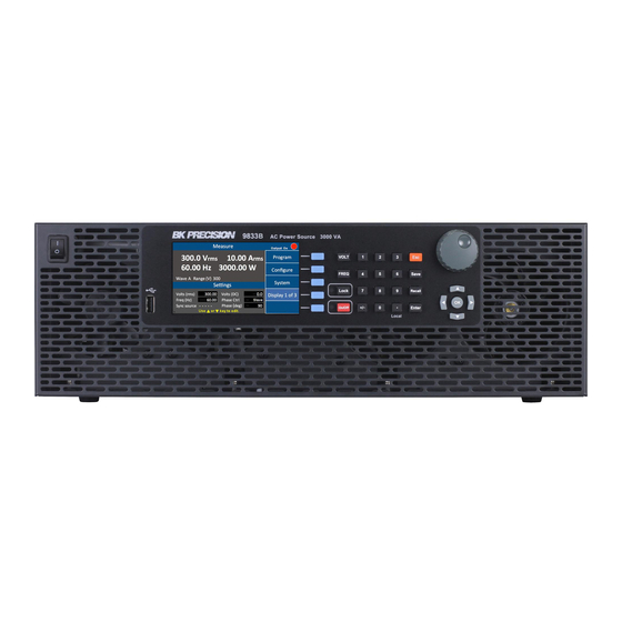
General Information The B&K Precision 9830B series are low distortion single phase AC power sources delivering a maximum of 3000 VA, 300 Vrms, 30 Arms /97.5 Apk. The Output frequency is adjustable from 45 Hz to 1200 Hz. All models are capable of outputting AC, DC or AC+DC. Predefined waveforms include sine, square, clipped sine and THD waveforms. -
Page 15: Product Dimensions
Note: Check that you have the most current User manual. This is available for download at www.bkprecision.com 3.2 Product Dimensions Figure 1 - Dimensions... -
Page 16: Installation
3.3 Installation The following diagram shows how to install the optional rack mount kit. Figure 2 - Rack Mount Kit... -
Page 17: Front Panel
3.4 Front Panel Figure 3 - Front Panel ① Power ON/OFF ② USB disk port ③ VFD ④ Softkeys ⑤ Function keys & Indicator LEDs ⑥ Number keys ⑦ Function keys ⑧ Rotary knob ⑨ Direction keys... - Page 18 Definition Frequency key, press to set the output frequency Voltage key, press to set the output voltage Press to lock the keyboard, (Keyboard is locked when LED is illuminated). Output On/Off key, press to enable/disable voltage output, (Output is On when LED is illuminated). Number key 1 to 9 for direct numeric entry.
-
Page 19: Rear Panel
3.5 Rear Panel Figure 4 - Rear Panel ⑩ AC output terminal ⑪ Remote sense terminal ⑫ ANALOG connector ⑬ DIGITAL Input /Output ⑭ LAN port ⑮ USB port (USBVCP or USBTMC) ⑯ GPIB port ⑰ Ground wire ⑱ AC input terminal... -
Page 20: Display Overview
Display Overview The power on screen shows the model number and self-test status. The Interface, and Power module should indicate OK. The (Real Time Clock), RTC will show the battery voltage. When the self-test completes, the instrument will advance to the Settings and Measure screen. This process takes approximately 7 seconds. - Page 21 Figure 6 - Display Description The instrument provides 3 display screen options for accessing commonly used measurements and settings. Each of these screens can be selected by pressing the softkey Display x of x repeatedly. Figure 7 - Display 1 of 3 Parameter Description Volts (rms)
- Page 22 Figure 8 - Display 2 of 3 Display 3 of 3 This displays shows a graphical representation of the settings, output measurements and waveforms. Figure 9 - Display 3 of 3 Press the ◄ ► keys to select and view V (voltage waveform) or A (current waveform). Then press the ▲...
-
Page 23: Getting Started
Getting Started Before connecting and powering up the instrument, please review and go through the instructions in this chapter. 5.1 Input Power Requirements The AC input accepts line voltage input within: Voltage: 190 V – 250 V Frequency: 47 Hz – 63 Hz Maximum power consumption: 9832B: 2500 VA;... - Page 24 current required to operate the instrument. 2. Using the power cable provided, identify the end that plugs into the instrument. Before disassembling the black hooded connector, make a note of how the unit is assembled from the factory so it can be correctly reassembled. 3.
-
Page 25: Fuse
up and reinstall the 4 screws into the hood. The green connector should be locked in place. Caution Label Latch Fingers Key section 4. Using the (2) screws provided with the cable, secure the assembled connector to the back of the instrument as shown in Figure 10 – Securing. Note: Use only the screws provided. -
Page 26: Warm-Up Time
instrument. The AC voltage range must meet per the acceptable specifications. 4. Connect Power 5. Connect specified AC power cord and verify the hood is in place and correctly secured to rear panel. 6. Press the power switch to the “|”... - Page 27 as short as possible. The local sense is the default configuration. When remote sense is selected, both the sense end L and output end L are connected to the load end L, whereas both sense end N and output end N are connected to the load end N. Figure - 11 Sense Lines...
-
Page 28: Menu Tree
Menu Tree... -
Page 29: Front Panel Operation
Front Panel Operation 7.1 Configure Voltage and Frequency Output 7.1.1 Setting voltage Press VOLT or the ▲ ▼ (arrow keys) to move the cursor to Volts (rms). Then press the ENTER key. There are three ways to set the value of the output voltage: 1. -
Page 30: Setting Voltage
Figure 12 - Setting Frequency 7.1.3 Setting Voltage Press the VOLT key, and a small window will pop-up. Pressing the VOLT key again will switch between VAC and VDC (when the coupling mode is “AC+DC”). Press the number keys to set the value, and press the OK or the Enter key to confirm the change. Optionally, press the ESC key to cancel the setting change. -
Page 31: Program Settings
7.2 Program Settings Press the Program softkey in the Setting and Measurement page to enter Program mode. There are three modes for the user to choose from to simulate Power Line Disturbances. They are: Step Output settings step-up or step-down based on user criteria. List Change the output sequentially by individual settings included in a list. - Page 32 Step Mode Operation Steps The following example for Step Mode waveform shows 4 steps starting at 40 volts and increasing 20 volts at each step. The instrument will dwell for 80 ms at each step. Figure 14 - Step Mode Example Output Parameters Settings Volts(rms)
-
Page 33: List Mode
1. Use the arrow keys (▲ ▼ ◄ ►) to move the cursor to the wanted parameter of the STEP setting page. 2. Press the ENTER key to adjust the parameter. Then press the ENTER key again to change its value. 3. - Page 34 Parameters Range Description List No. 0 to 9 Show configuration of a LIST Step No. 0 to 99 Show current edit step of list Volts (rms) Start 0 to 300 Set starting AC voltage Volts (rms) End 0 to 300 Set ending AC voltage Volts (DC) Start -424.0 to 424.0 Set starting DC voltage...
- Page 35 List operation pages Press the List softkey, refer to List Parameter Table for settings details. Figure 18 - List Mode first page Refer to Table 6 – List Mode First Page. The first page parameters are common to all the steps added under the second page parameters.
- Page 36 yellow boxes when no entries are stored in any List. Figure 19 - List Mode second page Refer to Error! Reference source not found.. Use the arrow key (▲ ▼) to move the cursor to the wanted parameter of List Step Configuration page. Press the ENTER key to change its value, then press the ENTER key again to confirm the change.
- Page 37 . Use the arrow keys (▲ ▼) to move the cursor to the wanted parameter of List Step Configuration page. Press the ENTER key to change its value, then press the ENTER key again to confirm the change. Parameters Values Volts (rms) Start Volts (rms) End Volts (DC) Start...
-
Page 38: Pulse Mode
changes in to memory and add a new step in List No. 0. The page with Empty Step field in yellow will change to 97 and Current Step to 3. All of the steps 0, 1 and 2 have been entered. - Page 39 Pulse Mode Operation Steps 1. Press Pulse softkey. 2. Use the arrow key (▲ ▼) to move the cursor to the wanted parameter. 3. Press the ENTER key to change its value then press the ENTER key again to confirm. Figure 24 - Pulse mode page 4.
-
Page 40: Configure Menu
Configure Menu In Setting and Measure page, press Configure key to open the Configuration page. The Configuration page includes three softkey options: 1. Config 1 (default) 2. Config 2 3. Limits Each of these pages will be explained below with more detail. Figure 26 - Default Configuration 1 Menu 8.1 Config 1 Configurations listed below can be edited in this Configuration 1 page. -
Page 41: Config 2
Press the arrow key (▲ ▼) to move the cursor to the wanted configuration. Press ENTER key to change its value, then press ENTER key to confirm. Figure 27 - Configuration 1 Move the cursor to Range (V) then Press ENTER key. Press 300 V key to put the supply in the high voltage range, then press Enter key to confirm. - Page 42 Output Timer ON or OFF Enable/disable the output timer. Note: This function is available in display 2 of 3 only. Timer Setting 0 to 99 (hours) : 0 to 59 Set the timing interval of output (H/M/S) (minutes): 0 to 59 timer.
-
Page 43: Limits
Press the arrow key (▲ ▼) to move the cursor to the wanted configuration. Press the ENTER key to change its value then press the ENTER again key to confirm. See the example below: Move the cursor to Waveform Select, then press OK or Enter. Press the A softkey then press OK or Enter to confirm. - Page 44 Press the arrow key (▲ ▼) to move the cursor to the wanted configuration. Press ENTER key to change its value, then press ENTER key to confirm. Figure 29 - Configure Limits Move the cursor to Volts (rms). Use ▲ ▼ keys (or Rotary knob) to set the value of Volts (rms) limit and other configurations.
-
Page 45: System Settings
System Settings 9.1 System Setup The System Setup page is used to set Date, Time, Brightness and Beep. Figure 30 - System Setup Press the arrow keys (▲ ▼) to move the cursor to the wanted configuration. Press the ENTER key to change its value and then press the ENTER key again to confirm the changes. -
Page 46: Communication Setup
9.2 Communication Setup The Communication Setup page is used to select and configure the communications ports. Figure 31 - Communication Setup Press the arrow keys (▲ ▼) to move the cursor to the wanted configuration. Press the ENTER key to change its value and then press the ENTER key again to confirm the changes. -
Page 47: System Error
9.3 System Error The System Clear Error page is used to view and clear the error log. Use + - key or rotary knob to see other error messages. Figure 32 System Error Log To clear the error log Press the arrow key (▲ ▼) to move the cursor to Clear Error? (Yes/No) then press the ENTER key to change its value. -
Page 48: System Next
Table 15 - Error Code Definitions 9.4 System Next The System Next page is used to access to system defaults and calibration functions. Figure 33 - System Next Page 9.5 Recall Default Press System softkey, then press Next softkey to go to the next function page. At the System Next screen press Recall Default softkey. - Page 49 (User) Freq(Hz) (User) Sync Source Phase (User) Phase(deg) (Inrush) Measurement Time(ms) (Inrush) Delay Time(ms) Waveform Select Waveform A Type Sine Wave A Index ----, 0 Waveform B Type Sine Wave B Index ----, 0 Wave B Index 0 Output Timer Timer Setting --:--:-- External Ref.
-
Page 50: Save
10 Save The Instrument can save data and screen shots into the USB disk (only FAT format is supported). Figure 35 - Save Menu 10.1 Save Config Press Save Config softkey to store all configurations and settings into the internal memory (CFGFile01.cfg to CFGFile09.cfg) or into a USB disk (CFGFile10.cfg to CFGFile99.cfg). -
Page 51: Save Screen
10.2 Save Screen Plug in a USB disk, then press the Save Screen softkey to take a screen shot and store the image to a USB disk (SCRFile000.bmp to SCRFile999.bmp). Use number keys to enter the file name. Then press OK or ENTER key to confirm or press ESC key to cancel. Figure 37 - Save Screen 10.3 Recall Configuration Figure 38 - Recall page... - Page 52 Press Recall Config softkey to recall configurations and settings from internal memory (CFGFile01.cfg to CFG09File.cfg) or from a USB disk (CFGFile10.cfg to CFGFile99.cfg). Use the number keys to enter the file name. Then press OK or ENTER key to confirm, or press ESC key to cancel.
-
Page 53: 11 3-Phase Operation
3-Phase kit option (TL983P-KIT) Limitations 9830B Series programming features including step, list, pulse, and amplifier mode are disabled in 3-phase mode. Several configuration settings (Config 1 and Config 2) remain enabled in 3- phase mode. Range, coupling mode, power on state, and inrush current measurement settings can be adjusted in 3-phase mode under the Config 1 menu. - Page 54 RJ45 cables Additional phases require additional AC sources and TL983P modules. Front panel configuration After verifying the TL983P adapters are properly wired on the rear panel, the AC sources must be configured from the front panel. 3-phase operation is enabled by setting the phase control field on each AC source.
-
Page 55: 3-Phase Ddapter Digital I/O Pin Definitions
Similarly, after setting the master set ‘Phase Ctrl’ of the remaining two AC sources to ‘Slave’. The slaves will automatically connect to the master. This completes the set-up process for three phase operation. 3-Phase parameters and output 3-Phase parameters include: Voltage (rms), Frequency (Hz), and Phase (deg). The reference phase of the master is always fixed at 0 degrees. -
Page 56: 3-Phase Output Wiring
11.3 3-Phase Output Wiring The 9830B Series supports a Y-configuration in 3-phase mode. Connect the N(-) terminals on the rear panel together as shown in Figure 11.3 Neutral Line Line Neutral Line... -
Page 57: Phase Control Software
11.4 Phase Control Software The 9830B Series Phase control software can be downloaded from bkprecision.com by visiting the 9830B product page and clicking the ‘Docs & Software’ tab. Phase control software allows you to easily control 9832B/9833B models in three-phase or multi-phase modes with data logging and live output monitoring capabilities. - Page 58 Three-Phase Application Mode Control Panel Multi-phase Application Mode This mode is intended for applications requiring control over more than three phases or when the user wants independent control of each AC source Voltage (Vrms) and Phase (degrees) parameters. Up to 31 instruments can be connected in multi-phase application mode.
-
Page 59: Setup And Configuration
11.4.2 Setup and Configuration Before attempting to connect to a computer, the 9832B/9833B AC Power Sources must be properly configured from the front panel and connected using phase sync adapter modules. See the 3-Phase Operation section above for instructions. On the front panel, set each AC source to ‘USBVCP’ in the communication settings. Figure 40 - Communication Setup Press the arrow keys (▲... - Page 60 1. Open the phase control software and click the icon to open the windows device manager. Three connected AC Sources should be displayed under ‘Ports (COM & LPT)’ in the device manager as shown: If they are missing or shown with an error power off and disconnect the AC Sources from the computer.
- Page 61 Click ‘Set’ to send the parameters and prepare the 3-Phase system for output. Output Click ‘Output On’ to enable the output of the 3-Phase system. Fields will be highlighted in green when the output is enabled. The Output Monitor panel displays live Voltage (Vrms), Current (Arms), Power (VA), and Power (W).
-
Page 62: Multi-Phase Application Mode
Check the box to enable data logging and set the desired sampling interval. The sampling interval is displayed in seconds (s). Data logging will start when the output is enabled. Output Timer The output timer is used to disable the output after a certain period of time. The timer can be set from 1 second to over 277 hours. - Page 63 1. Click the icon to open the windows device manager. Three connected AC Sources should be displayed under ‘Ports (COM & LPT)’ as shown: If they are missing or shown with an error power off and disconnect the AC Sources from the computer.
- Page 64 Click ‘Output On’ to enable the output of the multi-phase system. Fields will be highlighted in green when the output is enabled. The Output Monitor panel displays live Voltage (Vrms), Current (Arms), Power (VA), and Power (W). Click ‘Output Off’ to disable the output of the system. Data Logging This software is capable of logging time, voltage (Vrms), current (Arms), power (VA), and power (W) at user-defined sampling intervals for each AC Source.
- Page 65 Check the box to enable data logging and set the desired sampling interval. The sampling interval is displayed in seconds (s). Data logging will start when the output is enabled. Output Timer The output timer is used to disable the output after a certain period of time. The timer can be set from 1 second to over 277 hours.
-
Page 66: Remote Interface Operation
12 Remote Interface Operation The Instrument comes with RS232, USB (USBTMC, and USBVCP), GPIB, LAN and analog interfaces. Users can program the Instrument using the SCPI (Standard Commands for Programmable Instruments) commands through any of the remote interfaces. Only one interface at a time can be enabled and used to control the Instrument. -
Page 67: Usbtmc
12.1.3 USBTMC The USB port is USBTMC-compliant and can be used for remote communication and control. There are no additional settings in the menu system for USB configuration. The only requirement is that the USBTMC driver be installed. It is included when installing VISA software on the computer. - Page 68 Figure 41 - Web Login Page A password is required to login and access the menu items on the page. The default admin password is 123456. The web server menu items are described below: HOME This page provides general information about the instrument, Manufacturer, Model Number, Serial Number, Firmware version, Interface, USBTMC setting, MAC address, and IP Address.
- Page 69 LAN Config This page provides settings and status of LAN, including IP address, IP subnet, Gateway, DNS server, Hostname, Domain, mDNS host name, TCP/IP VXI-11 instrument, and TCP/IP Raw Socket. Figure 43 - LAN Config Config The Config page provides different settings output voltage range, waveform A/B, output type, inrush current.
- Page 70 Control The Control page provides the general control of the instrument such as output on/off as well as the AC/DC voltage and frequency settings. The command line for SCPI commands can also be accessed here. Figure 45 - Source Control Log Out The Log Out will exit the web page and go back to login screen.
-
Page 71: Digital I/O
13 Digital I/O The digital I/O interface is used to control or monitor the Instrument. Refer to the figure below describing the digital I/O 25-pin. Figure 46 - Digital IO Pinout Name Definition Range Ext_V External reference voltage input pin. (reference -10 V to 10 V (DC) ground: AGND) 0 to +10 V (AC) -
Page 72: External Voltage Control
Event_SW+ Built-in switch + (control the switch on or switch off via the SCPI commands) AGND Analog ground NONE /Fault_out When protection status is active, the voltage 5 V, 0 V, 1 mA level of this pin will turn from high to low. (reference ground: DGND) /Trigger_in When this pin receives a falling edge, it will... -
Page 73: Ac Couple
To activate this function, configure the settings below: Configure → Config 2 → External Ref. → Level Figure 48 - External Reference Voltage Function 13.1.1 AC Couple AC couple is selected by setting: Configure → Config 1 → Couple → AC. The reference voltage is proportional to the Instrument voltage. -
Page 74: Vdc
Ext_OnOff (external output control) according to the following control table and timing diagram. /Trigger_in /Ext_OnOff Result Falling Edge Instrument output STOP Falling Edge HIGH Instrument output ON HIGH No change HIGH HIGH No change Falling Edge Instrument output STOP HIGH Instrument output ON Table 19 - Control Table Figure 49 - Trigger Timing Diagram... -
Page 75: Output Status Detection
13.4 Output Status Detection The digital IO interface has system status logic outputs that are described in this section. All these outputs are in reference to DGND, pins 8, 10, 18, 20, and 22. Figure 51 - Output status pin out 13.4.1 /SYNC When the output sine wave of the Instrument is about to pass through 0 degrees, pin 9... -
Page 76: Fault_Out
13.4.2 /Fault_out Pin 16 (/Fault_out) indicates when a fault occurs or the Instrument is in protection status. During normal operation, the voltage level of this pin stays high (5 V). The voltage level will be low (0 V) if any of the circumstances below occurs: 4. -
Page 77: Remote_Inhibit
13.5 Remote_Inhibit The Instrument offers a remote inhibit used to turn the output off. The voltage level of pin 19 (Remote_inhibit) (reference ground is DGND) has to be set high (5 V) first, or the Instrument will enter into protection mode. If the voltage level drops to 0 V, the Instrument will stop outputting, and will show ‘Error Remote Inhibit ON’. -
Page 78: Event_Sw
The RS232 interface does not support flow control. The programmer should be aware of this limitation and pay attention to the Instrument command process time. If the remote commands are sent too fast the internal buffer may overrun and cause communication errors. Therefore, it is mandatory to add a delay between commands so that the Instrument has sufficient time to process. -
Page 79: Analog Input (Bnc)
13.8 Analog input (BNC) The analog input(BNC) is used to control the output voltage of the instrument with an external signal. In this example, an Arbitrary waveform generator is connected. Figure 57 Configuration 1 page Figure 58 – Analog Input Connection... - Page 80 Press Configure softkey in the Setting and Measurement screen. Configure as follows: Config 1(default) → Config 2 → Limits Press Config 2 softkey to enter the Configuration 2 setting page. Use the arrow key (▲ ▼) to move the cursor to the External Ref., then press the ENTER key to change value. Select the Amp softkey and press ENTER to save the setting.
-
Page 81: Built-In Harmonic Wave
14 Built-in Harmonic Wave THD 00 Harmonic weight(%) 2.07 9.8 15.8 2.16 THD 01 Harmonic weight(%)) THD 02 Harmonic weight(%) - Page 82 THD 03 Harmonic weight(%) THD 04 Harmonic weight(%)
- Page 83 THD 05 Harmonic weight(%) 1.65 4.2 3.45 1.05 3 THD 06 Harmonic weight(%)
- Page 84 THD 07 Harmonic weight(%) THD 08 Harmonic weight(%) 7.35 2.4 4.05 2.1 1.05 3 1.65 1.05 1.05 1.2 1.05...
- Page 85 THD 09 Harmonic weight(%) THD 10 Harmonic weight(%) 17.8...
- Page 86 THD 11 Harmonic weight(%) 21.3 THD 12 Harmonic weight(%) 24.5...
- Page 87 THD 13 Harmonic weight(%) 15.8 2.5 THD 14 Harmonic weight(%) 1.15 4.9 1.25...
- Page 88 THD 15 Harmonic weight(%) 2.45 3.95 THD 16 Harmonic weight(%) 4.05 2...
- Page 89 THD 17 Harmonic weight(%) 7.17 3.42 0.8 THD 18 Harmonic weight(%) 8.11 3.48 1...
- Page 90 THD 19 Harmonic weight(%) 9.38 3.44 1.15 THD 20 Harmonic weight(%) 1.23 0.9...
- Page 91 THD 21 Harmonic weight(%) 2.75 2.4 THD 22 Harmonic weight(%) 4.15 3.8 3.24 2.6 1.25...
- Page 92 THD 23 Harmonic weight(%) 5.63 5.13 4.42 3.56 2.63 1.68 0.79 1.04 1.27 1.32 1.2 0.95 THD 24 Harmonic weight(%) 7.28 6.63 5.71 4.61 3.42 2.19 1.04 1.32 1.63 1.69 1.54 1.22...
- Page 93 THD 25 Harmonic weight(%) 3.54 2.68 8.87 7.86 1.04 4.11 4.13 2.61 2.82 THD 26 Harmonic weight(%) 1.38 5.39 2.29...
- Page 94 THD 27 Harmonic 13 15 17 19 21 23 25 27 29 31 33 35 37 39 weight(%) 33 20 14 11 8.5 7.2 6 4.5 4 3.5 3 2.5 2 THD 28 Harmonic 11 13 15 17 19 21 23 25 27 29 31 33 35 37 39 weight(%) 33 20 14 11 8.5 7.2 6 4.5 4...
- Page 95 THD 29 Harmonic weight(%) 33.3 20 13.8 10.8 8.5...
-
Page 96: Calibration
15 Calibration B+K Precision recommends a calibration interval of one year for this instrument. To perform the calibration, the following equipment is required: 5 1/2 digital multimeter (DMM); B+K Precision 5492B or equivalent DC source: BK Precision 9110 or equivalent... -
Page 97: Range Calibration
Calibration is performed for both the 150V range and the 300V range. The following steps repeat for each range: 15.1.1 300V range calibration 1. Press Configure in the Setting and Measurement screen. Select 300V for the Range (V). Return to Setting and Measurement screen and select System → Next → Calibration and enter the password 13579. -
Page 98: Range Calibration
The calibration date and time will be shown at the bottom of the screen. Next, calibrate Freq2, Freq3 and Freq4 successively to complete the Range(V) 300V calibration. 15.1.2 150V range calibration Press ESC key to return to Setting and Measurement screen and press Configure. Select 150V for Range (V). -
Page 99: Ac Current Calibration
“OK” after the Low Point(V). 2. Press Cal. softkey to start calibration. The instrument will output ML Point voltage. Use the number keys to enter the voltage shown on the DMM. Use the number keys to enter the voltage shown on the DMM. Press ENTER, and the instrument will show “OK”... -
Page 100: Restore To Factory Default (Recall Data)
1. Connect the DMM to both ends of the shunt. Set the DMM to measure AC voltage. 2. Press the System → Next → Calibration → softkeys. Enter the password 13579. 3. Then select Imeas (AC current) on the calibration menu. Freq1, Freq2, Freq3 and Freq4 represent output frequency of 100Hz, 400Hz, 800Hz and 1200Hz respectively. -
Page 101: External Voltage Calibration
15.1.6 External Voltage Calibration Connect a DC power supply to pin 1 and pin 14 of Digital IO. The DC power must be able to supply 10V. CAUTION: The DC source for external voltage control and the DC source for external voltage calibration should be identical. - Page 102 4. Input 9V from the external DC power supply. The ADC value should be 14900±300, then press the Next point softkey to calibrate the second point. 5. Supply 0V from the external DC power supply. The AD value should be 7900±300, then press the Next point softkey to calibrate the third point.
- Page 103 1. The instrument will show “Cal End”, then press ESC to complete the external voltage calibration.
-
Page 104: Specifications
16 Specifications Note: All specifications apply to the unit after a temperature stabilization time of 15 minutes over an ambient temperature range of 23 °C ± 5 °C. Specifications are subject to change without notice. Model 9832B 9833B AC Output Output Phase Single Max. - Page 105 Programming Voltage 0.1 V Phase 0.1 degrees Resolution Hz (< 100 Hz) Frequency 0.1 Hz (>100 Hz) AC 0.2% + 0.2% of F.S. Voltage DC 0.2% + 0.4% of F.S. Accuracy Phase 0.15 % Frequency ± 1 % (45 Hz to 100 Hz) Measurement Voltage 0.1 V...
- Page 106 Operating Temperature 32 °F to 104 °F (0 °C to 40 °C) Storage Temperature -40 °F to 185 °F (-40 °C to 85 °C) Environmental Conditions 80% Relative Humidity up to 35 °C, non-condensing Dimensions ( W×H×D ) 16.5” x 5.2” x 22” (420 x 132 x 560 mm) Weight 52.9 lbs.
-
Page 107: Limited Three-Year Warranty
17 LIMITED THREE-YEAR WARRANTY B&K Precision Corp. warrants to the original purchaser that its products and the component parts thereof, will be free from defects in workmanship and materials for a period of three years from date of purchase. B&K Precision Corp. will, without charge, repair or replace, at its option, defective product or component parts. - Page 108 22820 Savi Ranch Parkway Yorba Linda, CA 92887 www.bkprecision.com © 2020 B&K Precision Corp. Printed in Taiwan v081720...
Need help?
Do you have a question about the 9830B Series and is the answer not in the manual?
Questions and answers