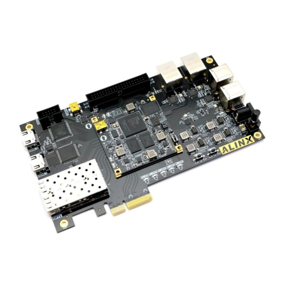
Alinx ZYNQ7000 FPGA User Manual
Hide thumbs Also See for ZYNQ7000 FPGA:

Advertisement

Quick Links

ZYNQ7000 FPGA
Development Board
AX7015
User Manual

Advertisement

Table of Contents
loading
Need help?

Need help?

Do you have a question about the ZYNQ7000 FPGA and is the answer not in the manual?

Questions and answers

Summary of Contents for Alinx ZYNQ7000 FPGA

  • Page 1 ZYNQ7000 FPGA Development Board AX7015 User Manual...
  • Page 2: Version Record

    ZYNQ FPGA Development Platform AX7015 User Manual Version Record Version Date Release By Description Rev 1.0 2019-03-31 Rachel Zhou First Release 2 / 60 Amazon Store: https://www.amazon.com/alinx...
  • Page 3: Table Of Contents

    Part 3.10: JTAG Interface ..................53 Part 3.11: LED Light ....................54 Part 3.12: User Button .................... 56 Part 3-13: Expansion Port ..................57 Part 3.14: Power Supply ..................58 Part 3.15: Expansion Board Structure diagram ............60 3 / 60 Amazon Store: https://www.amazon.com/alinx...
  • Page 4 ZYNQ FPGA Development Platform AX7015 User Manual This ZYNQ7000 FPGA development platform adopts the core board + expansion board mode, which is convenient for users to use the core board for secondary development. The core board uses XILINX's Zynq7000 SOC chip XC7Z015 solution, which combines dual-core ARM Cortex-A9 and FPGA programmable logic on a single chip using ARM+FPGA SOC technology.
  • Page 5 ZYNQ FPGA Development Platform AX7015 User Manual 5 / 60 Amazon Store: https://www.amazon.com/alinx...
  • Page 6: Part 1: Fpga Development Board Introduction

    4-port USB2.0 HOST interfaces, 1-port HDMI input interface, 1-port HDMI output interface, 1-port UART serial port interface, 1-port SD card interface, 1-port 40-pin expansion header and some button LEDs. Figure 1-1-1 is the block diagram of the FPGA development board AX7015: 6 / 60 Amazon Store: https://www.amazon.com/alinx...
  • Page 7 The network interface chip uses Micrel's KSZ9031 industrial grade GPHY chip, one Ethernet connection to the PS end of the ZYNQ chip, and one Ethernet connections to the PL end of the 7 / 60 Amazon Store: https://www.amazon.com/alinx...
  • Page 8  40-pin Expansion Header The 40-pin 2.54mm pitch expansion port use for external ALINX modules (binocular camera, TFT LCD screen, high-speed AD module, etc.). The expansion port includes 1 channel of 5V power supply, 2 channels of 3.3V power supply, 3 channels of ground, and 34 channels of IO port.
  • Page 9: Part 2: Ac7015 Core Board

    USB interface of the PS side, the Gigabit Ethernet interface, the SD card interface and other remaining MIO ports. Extend ZynQ's 4- pair high-speed transceiver GTP interface. Almost all IO ports (84) of BANK13, 9 / 60 Amazon Store: https://www.amazon.com/alinx...
  • Page 10 Moreover, the IOs connection part, the routing between the ZYNQ FPGA chip and the interface is equal length and differential processing. The core board size is only 60*60 (mm), which is very suitable for secondary development. Figure 2-1-1: AC7015 Core board Front 10 / 60 Amazon Store: https://www.amazon.com/alinx...
  • Page 11: Part 2.2: Zynq Chip

    SD/SDIO interface, I2C bus interface, CAN bus interface, UART interface, GPIO etc. The PS can operate independently and start up at power up or reset. Figure 2-2-3 detailed the Overall Block Diagram of the ZYNQ7000 Chip. 11 / 60 Amazon Store: https://www.amazon.com/alinx...
  • Page 12  Two CAN2.0B bus interfaces  Two SD card, SDIO, MMC compatible controllers  2 SPIs, 2 UARTs, 2 I2C interfaces  4 groups of 32bit GPIO, 54 (32+22) as PS system IO, 64 connected to PL 12 / 60 Amazon Store: https://www.amazon.com/alinx...
  • Page 13 XC7Z015-2CLG485I chip speed grade is -2, industrial grade, package is BGA484, pin pitch is 0.8mm, the specific chip model definition of ZYNQ7000 series is shown in Figure 2-2-2 Figure 2-2-2: The Specific Chip Model Definition of ZYNQ7000 Series 13 / 60 Amazon Store: https://www.amazon.com/alinx...
  • Page 14: Part 2.3: Ddr3 Dram

    We have fully considered the matching resistor/terminal resistance, trace impedance control, and trace length control in circuit design and PCB design to ensure high-speed and stable operation of DDR3. The hardware connection of DDR3 DRAM is shown in Figure 2-3-1: 14 / 60 Amazon Store: https://www.amazon.com/alinx...
  • Page 15 DDR3 DRAM Pin Assignment Signal Name ZYNQ Pin Name Pin Number DDR3_DQS0_P PS_DDR_DQS_P0_502 DDR3_DQS0_N PS_DDR_DQS_N0_502 DDR3_DQS1_P PS_DDR_DQS_P1_502 DDR3_DQS1_N PS_DDR_DQS_N1_502 DDR3_DQS2_P PS_DDR_DQS_P2_502 DDR3_DQS2_N PS_DDR_DQS_N2_502 DDR3_DQS3_P PS_DDR_DQS_P3_502 DDR3_DQS4_N PS_DDR_DQS_N3_502 DDR3_D0 PS_DDR_DQ0_502 DDR3_D1 PS_DDR_DQ1_502 DDR3_D2 PS_DDR_DQ2_502 DDR3_D3 PS_DDR_DQ3_502 15 / 60 Amazon Store: https://www.amazon.com/alinx...
  • Page 16 DDR3_A4 PS_DDR_A4_502 DDR3_A5 PS_DDR_A5_502 DDR3_A6 PS_DDR_A6_502 DDR3_A7 PS_DDR_A7_502 DDR3_A8 PS_DDR_A8_502 DDR3_A9 PS_DDR_A9_502 DDR3_A10 PS_DDR_A10_502 DDR3_A11 PS_DDR_A11_502 DDR3_A12 PS_DDR_A12_502 DDR3_A13 PS_DDR_A13_502 DDR3_A14 PS_DDR_A14_502 DDR3_BA0 PS_DDR_BA0_502 DDR3_BA1 PS_DDR_BA1_502 DDR3_BA2 PS_DDR_BA2_502 DDR3_S0 PS_DDR_CS_B_502 DDR3_RAS PS_DDR_RAS_B_502 DDR3_CAS PS_DDR_CAS_B_502 16 / 60 Amazon Store: https://www.amazon.com/alinx...
  • Page 17: Part 2.4: Qspi Flash

    ZYNQ chip. In the system design, the GPIO port functions of these PS ports need to be configured as the QSPI FLASH interface. Figure 2-4-1 shows the QSPI Flash in the schematic. QSPI_CS QSPI_SCK QSPI FLASH ZYNQ BANK (W25Q256F) QSPI_D0~QSPI_D3 Figure 2-4-1: QSPI Flash in the schematic 17 / 60 Amazon Store: https://www.amazon.com/alinx...
  • Page 18: Part 2.5: Emmc Flash

    Table 2-5-1: eMMC FLASH Specification eMMC FLASH is connected to the GPIO port of the BANK501 in the PS section of the ZYNQ chip. In the system design, the GPIO port functions of these 18 / 60 Amazon Store: https://www.amazon.com/alinx...
  • Page 19: Part 2.6: Clock Configuration

    PS_MIO47_501 MMC_D0 PS_MIO46_501 MMC_D1 PS_MIO49_501 MMC_D2 PS_MIO50_501 MMC_D3 PS_MIO51_501 Table 2-5-2: Pin Assignment of eMMC FLASH Part 2.6: Clock configuration The AC7015 core board provides active clocks for the PS system and the PL 19 / 60 Amazon Store: https://www.amazon.com/alinx...
  • Page 20 The AC7015 core board provides a single-ended 125MHz PL system clock source with 3.3V power supply. The crystal output is connected to the global clock (MRCC) of the FPGA BANK13, which can be used to drive user logic within the 20 / 60 Amazon Store: https://www.amazon.com/alinx...
  • Page 21: Part 2.7: Usb To Serial Port

    CP2102GM. The USB interface uses the MINI USB interface. It can be connected to the USB port of the upper PC with a USB cable for separate power supply and serial data communication of the core board. 21 / 60 Amazon Store: https://www.amazon.com/alinx...
  • Page 22: Part 2.8: Led Light

    FPGA is configured, the configuration LED will illuminate. Two user LED lights are connected to the MIO of the PS, one is connected to the IO of the PL, the user can control the lighting and off by the 22 / 60 Amazon Store: https://www.amazon.com/alinx...
  • Page 23 The schematic diagram of the LED light hardware connection is shown in Figure 2-8-1: 3.3V 3.3V 3.3V LED1 LED2 BANK ZYNQ BANK 3.3V BANK DONE Figure 2-8-1: The schematic diagram of the LED light hardware connection 2-8-2: LED light on the Core Board Figure 23 / 60 Amazon Store: https://www.amazon.com/alinx...
  • Page 24: Part 2.9: Reset Button

    Figure 2-9-1: Reset button connection diagram Figure 2-9-2: Reset button on the Core Board Reset Pin Assignment: Signal Name ZYNQ Pin Name ZYNQ Pin Description Number PS_POR_B PS_POR_B_500 Reset Key Table 2-9-1: Reset Pin Assignment 24 / 60 Amazon Store: https://www.amazon.com/alinx...
  • Page 25: Part 2.10: Jtag Interface

    The AC7015 has a 2-digit DIP switch SW1 on the core board to configure the ZYNQ system's startup mode. The AC7015 system development platform supports three startup modes. The three startup modes are JTAG debug mode, QSPI 25 / 60 Amazon Store: https://www.amazon.com/alinx...
  • Page 26: Part 2.12: Power

    1.0V/5A Mini USB TPS54620 TLV62130R 1.8V/3A CON1 1.5V/3A TLV62130R TPS51200 VREF 3.3V/3A TLV62130R 0R(R74) 0R(R79) VCCIO35/0.5A VCCIO/0.5A SPX3819M5 -2-5 R79 Not installed by default Figure 2-12-1: The Power Supply Design on the Core Board 26 / 60 Amazon Store: https://www.amazon.com/alinx...
  • Page 27 +1.0V->+1.8V->(+1.5 V, +3.3V, VCCIO). The circuit design ensures the normal operation of the chip. The power supply on the core board detailed as Figure 2-12-2 below: 27 / 60 Amazon Store: https://www.amazon.com/alinx...
  • Page 28: Part 2.13: Structure Diagram

    ZYNQ FPGA Development Platform AX7015 User Manual Figure 2-12-2: The Power Supply on the Core Board Part 2.13: Structure diagram Figure 2-13-1: The Structure diagram (Top View) 28 / 60 Amazon Store: https://www.amazon.com/alinx...
  • Page 29: Part 2.14: Connector Pin Definition

    The IOs levels of BANK35 can be changed by changing the level of the LDO chip (U12) on the board. The default is 3.3V. Pin assignments detailed as Table 2-14-1, Table 2-14-2, Table 2-14-3, Table 2-14-4 29 / 60 Amazon Store: https://www.amazon.com/alinx...
  • Page 30 Signal Name CON1 Pin Signal Name Name Name PS_MIO13 ETH_TXD0 PS_MIO12 ETH_TXD1 ETH_TXD2 ETH_TXD3 ETH_TXCK ETH_TXCTL ETH_RXD3 ETH_RXD2 PS_MIO7 ETH_RXD1 PS_MIO8 ETH_RXD0 PS_MIO9 ETH_RXCTL PS_MIO11 ETH_RXCK ETH_MDC ETH_MDIO OTG_STP OTG_DIR XADC_VP OTG_CLK XADC_VN OTG_NXT OTG_DATA0 30 / 60 Amazon Store: https://www.amazon.com/alinx...
  • Page 31 Signal Name CON2 Pin Signal Name Name Name B34_L19_N B34_L13_N B34_L19_P B34_L13_P B34_L2_P B34_L21_N B34_L2_N B34_L21_P B34_L1_P B34_L12_N B34_L1_N B34_L12_P B34_L11_N B35_L4_P B34_L11_P B35_L4_N B35_L24_P B35_L19_P B35_L24_N B35_L19_N B34_L8_N B35_L22_P B34_L8_P B35_L22_N B35_IO25 B35_L21_P 31 / 60 Amazon Store: https://www.amazon.com/alinx...
  • Page 32 B35_L10_N B35_L3_N B35_L10_P B35_L8_P B35_L9_N B35_L8_N B35_L9_P B35_L7_P B35_L7_N Table 2-14-2: Pin Assignment of CON2 ZYNQ Pin ZYNQ Pin CON3 Pin Signal Name CON3 Pin Signal Name Name Name MGT_CLK0_P MGT_CLK0_N MGT_RX2_ N MGT_RX2_p 32 / 60 Amazon Store: https://www.amazon.com/alinx...
  • Page 33 ZYNQ FPGA Development Platform AX7015 User Manual MGT_RX1_P MGT_RX1_N MGT_TX2_P MGT_TX2_N MGT_TX1_P MGT_TX1_N MGT_RX3_N MGT_RX3_P MGT_RX0_P MGT_RX0_N MGT_TX3_P MGT_TX3_N MGT_TX0_P MGT_TX0_N B34_L3_P B34_L3_N B34_L4_N B34_L4_P B34_L14_N B34_L14_P B34_L20_N B34_L20_P B34_L9_N B34_L9_P B34_L10_N 33 / 60 Amazon Store: https://www.amazon.com/alinx...
  • Page 34 B13_L15_P AB21 B13_L11_N AA15 B13_L21_P B13_L11_P AA14 B13_L21_N B13_L17_P AB16 B13_L24_P B13_L17_N AB17 B13_L24_N B13_L16_N AB19 B13_L2_P B13_L16_P AB18 B13_L2_N B34_L22_P B13_L9_N AB14 B34_L22_N B13_L9_P AB13 B13_L12_N B13_L6_N B13_IO25 B13_L6_P B34_L6_P B34_L23_P B34_L6_N B34_L23_N 34 / 60 Amazon Store: https://www.amazon.com/alinx...
  • Page 35 AB12 B13_L1_P B13_L8_P AA12 B13_L7_N AB11 B34_L17_N B13_L7_P AA11 B34_L17_P B34_L24_P B34_L5_P B34_L24_N B34_L5_N B13_L4_P B34_L18_P B13_L4_N B34_L18_N B13_L3_P B13_L10_P B13_L3_N B13_L10_N B13_L5_N B34_L15_N B13_L5_P B34_L15_P B34_L16_N B34_L16_P Table 2-14-4: Pin Assignment of CON4 35 / 60 Amazon Store: https://www.amazon.com/alinx...
  • Page 36: Part 3: Extension Board

     4 ports USB HOST interface  1 port USB Uart communication interface  1 port SD card interface  2 ports 40-pin expansion port  JTAG debug interface  2 independent buttons 5 user LED lights  36 / 60 Amazon Store: https://www.amazon.com/alinx...
  • Page 37: Part 3.2: Gigabit Ethernet Interface

    125Mhz, and the data is sampled on the rising edge and falling samples of the clock. Figure 3-2-1 and Figure 3-2-2 detailed the connection of the ZYNQ chip end Ethernet PHY chip: 37 / 60 Amazon Store: https://www.amazon.com/alinx...
  • Page 38 ZYNQ FPGA Development Platform AX7015 User Manual Figure 3-2-1: The connection of the ZYNQ PS end and PHY chip Figure 3-2-2: The connection of the 4 ZYNQ PL end and PHY chip 38 / 60 Amazon Store: https://www.amazon.com/alinx...
  • Page 39 PS_MIO21_501 Transmit enable Signal PHY1_RXCK PS_MIO22_501 RGMII Receive Clock PHY1_RXD0 PS_MIO23_501 Receive data Bit0 PHY1_RXD1 PS_MIO24_501 Receive data Bit1 PHY1_RXD2 PS_MIO25_501 Receive data Bit2 PHY1_RXD3 PS_MIO26_501 Receive data Bit3 PHY1_RXCTL PS_MIO27_501 Receive enable Signal 39 / 60 Amazon Store: https://www.amazon.com/alinx...
  • Page 40 PHY2_RXD1 B35_L15_N Receive data Bit1 PHY2_RXD2 B35_L18_P Receive data Bit2 PHY2_RXD3 B35_L18_N Receive data Bit3 PHY2_RXCTL B35_L13_N Receive enable Signal PHY2_MDC B35_L7_P MDIO Management Clock PHY2_MDIO B35_L7_P DIO Management Data PHY2_RESET B35_L8_P Reset Signal 40 / 60 Amazon Store: https://www.amazon.com/alinx...
  • Page 41: Part 3.3: Usb 2.0 Host Interface

    OTG_NXT ZYNQ USB PHY USB Hub OTG_DIR DP/DM (USB3320C) (USB2514) OTG_DATA0~OTG_DATA7 OTG_RESET BANK Figure 3-3-1: The connection between Zynq7000 and USB chip Figure 3-3-2 shows the USB2.0 interface on the expansion board, where the 41 / 60 Amazon Store: https://www.amazon.com/alinx...
  • Page 42 PS_MIO34_501 USB Data Bit2 OTG_DATA3 PS_MIO35_501 USB Data Bit3 OTG_CLK PS_MIO36_501 USB Clock Signal OTG_DATA5 PS_MIO37_501 USB Data Bit5 OTG_DATA6 PS_MIO38_501 USB Data Bit6 OTG_DATA7 PS_MIO39_501 USB Data Bit7 OTG_RESETN PS_MIO8_500 USB Reset Signal 42 / 60 Amazon Store: https://www.amazon.com/alinx...
  • Page 43: Part 3.4: Hdmi Output Interface

    I2C pin. The hardware connection diagram of SIL9134 chip and ZYNQ7000 is shown in Figure 3-4-1. Figure3-4-1: The hardware connection of SIL9134 chip and ZYNQ7000 Figure3-4-2: The HDMI Output Interface on the Expansion Board 43 / 60 Amazon Store: https://www.amazon.com/alinx...
  • Page 44 B35_L5_N 9134 Video Signal Data 11 9134_D[12] B35_L6_P 9134 Video Signal Data 12 9134_D[13] B35_L6_N 9134 Video Signal Data 13 9134_D[14] B35_L1_N 9134 Video Signal Data 14 9134_D[15] B35_L1_P 9134 Video Signal Data 15 44 / 60 Amazon Store: https://www.amazon.com/alinx...
  • Page 45: Part 3.5: Hdmi Input Interface

    Among them, the IIC configuration interface of SIL9013 is connected with the IO of FPGA BANK13. ZYNQ initializes and controls the SIL9013 through I2C bus programming. The hardware connection of HDMI input interface is shown in Figure 3-5-1. 45 / 60 Amazon Store: https://www.amazon.com/alinx...
  • Page 46 Name Number 9013_nRESET B34_L16_N 9013 Reset Signal 9013_CLK B13_L14_P AA16 9013 Video signal clock 9013_HS B13_L20_P 9013 Video signal line synchronization 9013_VS B13_L22_N 9013 Video signal column synchronization 9013_DE B13_L20_N 9013 Video signal Enable 46 / 60 Amazon Store: https://www.amazon.com/alinx...
  • Page 47: Part 3.6: Sfp Interface

    The AX7015 expansion board has two optical interfaces. Users can purchase optical modules (1.25G, 2.5G optical modules on the market) and insert them into these two optical interfaces for optical data communication. The two fiber 47 / 60 Amazon Store: https://www.amazon.com/alinx...
  • Page 48 GTP transceiver is provided by a 125M differential crystal on the core board. Figure 3-6-1: The schematic diagram of FPGA and Fiber Interface Figure 3-6-2: The 2-Port Fiber Interface on the Expansion Board 48 / 60 Amazon Store: https://www.amazon.com/alinx...
  • Page 49: Part 3.7: Pcie X2 Interface

    PCIe x2 interface, that meets the standard PCIe card electrical specifications, and can be used directly on the PCIe slot of computer. The transmission and receive signals of the PCIe interface are directly 49 / 60 Amazon Store: https://www.amazon.com/alinx...
  • Page 50 The PCIe x2 interface FPGA pin assignments are as follows: Net Name FPGA Pin Description PCIE_RX0_P PCIE Channel 0 Data Receive Positive PCIE_RX0_N PCIE Channel 0 Data Receive Negative PCIE_RX1_P PCIE Channel 1 Data Receive Positive 50 / 60 Amazon Store: https://www.amazon.com/alinx...
  • Page 51: Part 3.8: Usb To Serial Port

    Figure 3-8-1 detailed the schematic diagram of the USB Uart circuit design Figure 3-8-1: USB Uart Circuit Design Figure 3-8-2: USB Uart on the Expansion Board 51 / 60 Amazon Store: https://www.amazon.com/alinx...
  • Page 52: Part 3.9: Sd Card Slot

    Since the VCCMIO of the BANK is set to 1.8V, but the data level of the SD card is 3.3V, connected through the TXS02612 level shifter. The schematic of the Zynq7000 PS and SD card connector is shown in Figure 3-9-1: Figure 3-9-1: SD Card Connection Diagram 52 / 60 Amazon Store: https://www.amazon.com/alinx...
  • Page 53: Part 3.10: Jtag Interface

    FPGA chip caused by hot plugging, a protection diode is added to the JTAG signal to ensure that the signal voltage is within the range accepted by the FPGA to avoid damage to the FPGA. 53 / 60 Amazon Store: https://www.amazon.com/alinx...
  • Page 54: Part 3.11: Led Light

    (PWR) and five of which are user LEDs (LED1~LED4). When the expansion board is powered, the power indicator will light up; one user LEDs are connected to the MIO of the PS, and the other four are connected to the IO of the 54 / 60 Amazon Store: https://www.amazon.com/alinx...
  • Page 55 ZYNQ Pin Description Number PS_LED PS_MIO9_500 PS end user LED PL_LED1 B35_L10_P PL end user LED1 PL_LED2 B35_L9_P PL end user LED2 PL_LED3 B35_L9_N PL end user LED3 PL_LED4 B35_L7_N PL end user LED4 55 / 60 Amazon Store: https://www.amazon.com/alinx...
  • Page 56: Part 3.12: User Button

    Figure 3-12-2: The User Button on the Expansion Board ZYNQ Pin Assignment for User Buttons Signal Name ZYNQ Pin ZYNQ Pin Description Name Number PS_KEY PS_MIO11_500 ZYNQ System Reset Signal PL_KEY B13_L8_N AB12 ZYNQ System Reset Signal 56 / 60 Amazon Store: https://www.amazon.com/alinx...
  • Page 57: Part 3-13: Expansion Port

    Part 3-13: Expansion Port The AX7015 expansion board is reserved one 2.54-mm standard 40-pin expansion ports J12, for connecting various modules of ALINX or external circuits designed by the user. The expansion port has 40 signals, of which 1 channel is 5V power supply.
  • Page 58: Part 3.14: Power Supply

    +5V power supply supplies power to the core board through the inter-board connector, the current output of the DC power supply is 3A, and the output current of the other three power supplies is 2A. Figure 3-14-1 is the power supply design of expansion board. 58 / 60 Amazon Store: https://www.amazon.com/alinx...
  • Page 59 ZYNQ FPGA Development Platform AX7015 User Manual Figure 3-14-1: Power Supply Schematic of Expansion Board Figure 3-14-2: Power Supply on the Expansion Board 59 / 60 Amazon Store: https://www.amazon.com/alinx...
  • Page 60: Part 3.15: Expansion Board Structure Diagram

    ZYNQ FPGA Development Platform AX7015 User Manual Part 3.15: Expansion Board Structure diagram Figure 3-15-1: Expansion Board Structure Diagram (Top View) 60 / 60 Amazon Store: https://www.amazon.com/alinx...

This manual is also suitable for:

Ax7015

Table of Contents