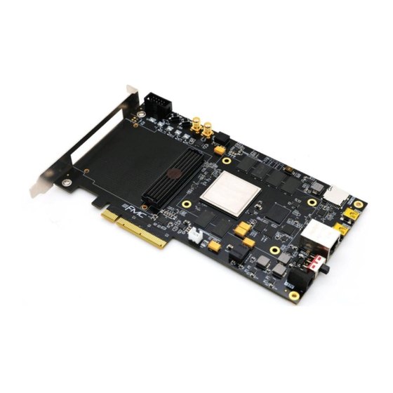
ZYNQ FPGA Development Board AX7450 User Manual Version Record Revision Date Release By Description Rev 1.0 2020-11-21 Rachel Zhou First Release 2 / 54 Amazon Store: https://www.amazon.com/alinx...
Part 13: LED Light....................44 Part 14: Reset Key and User Key..............46 Part15: SMA Interface..................47 Part16: JTAG debug port................... 48 Part 17: DIP Switch Configuration..............49 Part 18: Power Supply..................50 Part 19: Fan......................53 Part 20: Dimensional structure................54 3 / 54 Amazon Store: https://www.amazon.com/alinx...
Page 4
ZYNQ FPGA Development Board AX7450 User Manual The ZYNQ7000 FPGA development platform uses XILINX's Zynq7000 SOC chip XC7Z100 solution, which uses ARM+FPGA SOC technology to integrate dual-core ARM Cortex-A9 and FPGA programmable logic on a single chip. ZYNQ has two 512MB high-speed DDR3 SDRAM chips on the PS and four 512MB high-speed DDR3 SDRAM chips on the PL sides.
USB2.0 OTG interfaces, one UART serial interface, one SD card interface, one FMC expansion interface, two SMT interfaces, some keys and LEDs. Figure 1-1 is the Schematic diagram of the entire FPGA development boards: 5 / 54 Amazon Store: https://www.amazon.com/alinx...
Page 6
PL side to form a 64-bit data width and can be used as an FPGA Data storage, image analysis cache, data processing. eMMC The PS side mounts an 8GB eMMC FLASH memory chip to store user 6 / 54 Amazon Store: https://www.amazon.com/alinx...
Page 7
ALINXDE various FMC modules (HDMI input and output modules, binocular camera modules, high-speed AD modules etc.). The FMC expansion port contains 84 pairs of differential IO signals and 8 high-speed GTX transceiver signals. USB JTAG Interface 7 / 54 Amazon Store: https://www.amazon.com/alinx...
Page 8
LED Light 7 LEDs, 1 power indicator; 1 DONE configuration indicator; 4 user debugging LED lights, 1 front panel dual-color LED light. Keys 2 keys, 1 reset key , 1 PL user key. 8 / 54 Amazon Store: https://www.amazon.com/alinx...
The main parameters of the PS system part are as follows: dual-core CortexA9-based application processor, ARM-v7 architecture, up to 800MHz 32KB level 1 instruction and data cache per CPU, 512KB level 2 cache 9 / 54 Amazon Store: https://www.amazon.com/alinx...
Page 10
17 external differential input channels, 1MBPS XC7Z100-2FFG900I chip speed grade is -2, industrial grade, package is FGG900, pin pitch is 1.0mm the specific chip model definition of ZYNQ7000 series is shown in Figure 2-2 10 / 54 Amazon Store: https://www.amazon.com/alinx...
Page 11
ZYNQ FPGA Development Board AX7450 User Manual Figure 2-2: The Specific Chip Model Definition of ZYNQ7000 Series Figure 2-3: The XC7Z100 chip used on the Core Board 11 / 54 Amazon Store: https://www.amazon.com/alinx...
PCB design to ensure high-speed and stable operation of DDR3. The hardware connection of the DDR3 DRAM on the PS side is shown in Figure 3-1: 12 / 54 Amazon Store: https://www.amazon.com/alinx...
Page 13
Figure 3-1: The Schematic Part of DDR3 DRAM on the PS side The hardware connection of DDR3 DRAM on the PL side is shown in Figure 3-2: Figure 3-2: The Schematic Part of DDR3 DRAM on the PL side 13 / 54 Amazon Store: https://www.amazon.com/alinx...
ZYNQ chip. In the system design, the GPIO port functions of these PS ports need to be configured as the QSPI FLASH interface. Figure 4-1 shows the QSPI Flash in the schematic. 20 / 54 Amazon Store: https://www.amazon.com/alinx...
ZYNQ chip. In the system design, the GPIO port functions of these PS ports need to be configured as the SD interface. Figure 5-1 shows the eMMC Flash in the schematic. Figure 5-1: eMMC Flash in the Schematic 22 / 54 Amazon Store: https://www.amazon.com/alinx...
Page 23
ZYNQ FPGA Development Board AX7450 User Manual Pin Assignment of eMMC Flash Signal Name ZYNQ Pin Name ZYNQ Pin Number MMC_CCLK PS_MIO48_501 MMC_CMD PS_MIO47_501 MMC_D0 PS_MIO46_501 MMC_D1 PS_MIO49_501 MMC_D2 PS_MIO50_501 MMC_D3 PS_MIO51_501 23 / 54 Amazon Store: https://www.amazon.com/alinx...
The AX7450 FPGA development board provides a single-ended 50MHz PL system clock source with 1.8V supply. The crystal output is connected to the local clock (SRCC) of the FPGA BANK9, which can be used to drive user 24 / 54 Amazon Store: https://www.amazon.com/alinx...
Page 25
BANK111 as the reference clock of the GTX transceiver; the fourth reference clock is provided to the BANK 10, as the reference clock of FPGA BANK 10. The schematic diagram of the Si5338 circuit design is shown 25 / 54 Amazon Store: https://www.amazon.com/alinx...
7-1: Figure 7-1: USB to serial port schematic USB to serial port ZYNQ pin assignment: Signal name ZYNQ Pin Name ZYNQ Pin Description Number UART_RXD PS_MIO14_500 Uart data input UART_TXD PS_MIO15_500 Uart data output 27 / 54 Amazon Store: https://www.amazon.com/alinx...
When the network is connected to 100M Ethernet, the data transmission of ZYNQ and PHY chip KSZ9031RNX is communicated through RMII bus, and the transmission clock is 25Mhz. Data is sampled on the rising edge and falling samples of the clock. 28 / 54 Amazon Store: https://www.amazon.com/alinx...
Page 29
Receive data Bit0 PHY1_RXD1 PS_MIO24_501 Receive data Bit1 PHY1_RXD2 PS_MIO25_501 Receive data Bit2 PHY1_RXD3 PS_MIO26_501 Receive data Bit3 PHY1_RXCTL PS_MIO27_501 Receive data valid signal PHY1_MDC PS_MIO52_501 MDIO Management clock PHY1_MDIO PS_MIO53_501 MDIO Management data 29 / 54 Amazon Store: https://www.amazon.com/alinx...
Figure 9-1 Figure 9-1: The connection between Zynq7000 and USB chip USB2.0 Pin Assignment: Signal Name ZYNQ Pin Name ZYNQ Pin Description Number OTG_DATA4 PS_MIO28_501 USB Data Bit4 OTG_DIR PS_MIO29_501 USB Data Direction Signal 30 / 54 Amazon Store: https://www.amazon.com/alinx...
Page 31
PS_MIO34_501 USB Data Bit2 OTG_DATA3 PS_MIO35_501 USB Data Bit3 OTG_CLK PS_MIO36_501 USB Clock Signal OTG_DATA5 PS_MIO37_501 USB Data Bit5 OTG_DATA6 PS_MIO38_501 USB Data Bit6 OTG_DATA7 PS_MIO39_501 USB Data Bit7 OTG_RESETN PS_MIO7_500 USB Reset Signal 31 / 54 Amazon Store: https://www.amazon.com/alinx...
5G bit bandwidth. The PCIe interface schematic of the AX7450 FPGA development board is shown Figure 10-1, in which the TX signal is connected in AC coupling mode. Figure 10-1: PCIe Schematic 32 / 54 Amazon Store: https://www.amazon.com/alinx...
Page 33
PCIE channel 4 data receiving positive PCIE_TX4_N BANK111_TX3_N PCIE channel 4 data receiving negative PCIE_TX5_P BANK111_TX2_P PCIE channel 5 data receiving positive PCIE_TX5_N BANK111_TX2_N PCIE channel 5 data receiving negative PCIE_TX6_P BANK111_TX1_P PCIE channel 6 data receiving positive 33 / 54 Amazon Store: https://www.amazon.com/alinx...
Page 34
PCIE_TX6_N BANK111_TX1_N PCIE channel 6 data receiving negative PCIE_TX7_P BANK111_TX0_P PCIE channel 7 data receiving positive PCIE_TX7_N BANK111_TX0_N PCIE channel 7 data receiving negative PCIE_PERST IO_L12N_T1_MRC AD19 The reset signal of the PCIE board 34 / 54 Amazon Store: https://www.amazon.com/alinx...
The AX7450 FPGA development board has a standard FMC HPC expansion port that can be connected to various FMC modules of XILINX or ALINX (HDMI input and output modules, binocular camera modules, high-speed AD modules, etc.). The FMC expansion port contains 84 pairs of differential IO signals and one high-speed GTX transceiver signal.
Page 37
Channel data N FMC_LA10_P AJ15 FMC LA 10 Channel data P FMC_LA10_N AK15 FMC LA 10 Channel data N FMC_LA11_P AJ16 FMC LA 11 Channel data P FMC_LA11_N AK16 FMC LA 11 Channel data N 37 / 54 Amazon Store: https://www.amazon.com/alinx...
Page 38
Channel data P FMC_LA26_N AJ19 FMC LA 26 Channel data N FMC_LA27_P AJ20 FMC LA 27 Channel data P FMC_LA27_N AK20 FMC LA 27 Channel data N FMC_LA28_P AJ23 FMC LA 28 Channel data P 38 / 54 Amazon Store: https://www.amazon.com/alinx...
Page 39
Channel data N FMC_HA09_P AC26 FMC HA 9 Channel data P FMC_HA09_N AD26 FMC HA 9 Channel data N FMC_HA10_P AA27 FMC HA 10 Channel data P FMC_HA10_N AA28 FMC HA 10 Channel data N 39 / 54 Amazon Store: https://www.amazon.com/alinx...
Page 40
FMC_HB01_P FMC HB 1 Channel data P FMC_HB01_N FMC HB1 Channel data N FMC_HB02_P FMC HB 2 Channel data P FMC_HB02_N FMC HB 2 Channel data N FMC_HB03_P FMC HB 3 Channel data P 40 / 54 Amazon Store: https://www.amazon.com/alinx...
Page 41
FMC HB 17 Channel data (clock)N FMC_HB18_P FMC HB 18 Channel data P FMC_HB18_N FMC HB 18 Channel data N FMC_HB19_P FMC HB 19 Channel data P FMC_HB19_N FMC HB 19 Channel data N 41 / 54 Amazon Store: https://www.amazon.com/alinx...
Page 42
Transceiver data 1 input N FMC_DP2_C2M_P Transceiver data 2 input P FMC_DP2_C2M_N Transceiver data 2 input N FMC_DP3_C2M_P Transceiver data 3 input P FMC_DP3_C2M_N Transceiver data 3 input N FMC_DP4_C2M_P Transceiver data 4 input P 42 / 54 Amazon Store: https://www.amazon.com/alinx...
Page 43
Transceiver data 5 input P FMC_DP5_C2M_N Transceiver data 5 input N FMC_DP6_C2M_P Transceiver data 6 input P FMC_DP6_C2M_N Transceiver data 6 input N FMC_DP7_C2M_P Transceiver data 7 input P FMC_DP7_C2M_N Transceiver data 7 input N 43 / 54 Amazon Store: https://www.amazon.com/alinx...
IO of BANK10, and two-color LED lights are connected to the IO of BANK9. Figure 13-1 detailed the LED light hardware connection diagram Figure 13-1: The User LEDs Hardware Connection Diagram 44 / 54 Amazon Store: https://www.amazon.com/alinx...
16-1. Figure 14-1: Keys Connection Schematic ZYNQ pin assignment of the button Signal Name ZYNQ Pin Name ZYNQ Pin Description Number ZYNQ System Reset Signal PS_POR_B PS_POR_B_500 AC12 PL Key 1 input PL_KEY1 IO_L21N_T3_DQS_10 46 / 54 Amazon Store: https://www.amazon.com/alinx...
Figure 15-1: Figure 15-1: SMA Interface Schematic ZYNQ pin assignment of SMA Interface Signal Name ZYNQ Pin Name ZYNQ Pin Description Number SMA interface input 1 PS_POR_B PS_POR_B_500 SMA interface input 2 PL_KEY1 IO_L21N_T3_DQS_10 AC12 47 / 54 Amazon Store: https://www.amazon.com/alinx...
On the AX7350 FPGA development board, the JTAG interface is in the form of USB interface. Users can connect the PC and JTAG interface to the ZYNQ system debugging through the USB cable provided by us. 48 / 54 Amazon Store: https://www.amazon.com/alinx...
TLV62130. The VADJ and VIO_B of the FMC interface are generated by a PMIC power chip output, and these two power sources can be configured by software.The schematic diagram of the power supply design on the AX7450 FPGA development board is shown in Figure 18-1 50 / 54 Amazon Store: https://www.amazon.com/alinx...
Page 52
Because the power supply of the ZYNQ FPGA has the power-on sequence requirements, in the circuit design, we have designed according to power requirements chip. power-on sequence +1.0V->+1.8V->(+1.5 V, +3.3V, VCCIO) circuit design to ensure the normal operation of the chip. 52 / 54 Amazon Store: https://www.amazon.com/alinx...
The fan has been screwed to the AX7450 FPGA development board before leaving the factory. The power of the fan is connected to the socket of J8. The red is positive and the black is negative. 53 / 54 Amazon Store: https://www.amazon.com/alinx...
Need help?
Do you have a question about the ZYNQ7000 FPGA and is the answer not in the manual?
Questions and answers