Table of Contents
Advertisement
Advertisement
Table of Contents

Related Manuals for ADEEPT Robotic Arm


Summary of Contents for ADEEPT Robotic Arm
- Page 2 About Adeept Adeept is a technical service team of open source software and hardware. Dedicated to applying the Internet and the latest industrial technology in open source area, we strive to provide best hardware support and software service for general makers and electronic enthusiasts around the world.
- Page 3 Lesson 7 GUI application control mode................... 97 Lesson 8 GwBlock graphical control mode..................109 Lesson 9 Potentiometer control mode.....................135 Lesson 10 Learning mode....................... 142 Lesson 11 Processing controls robotic arm..................148 Lesson 12 Imitation function(Pen)....................162 Lesson 13 Processing controls robotic arm to write and draw............171...
- Page 4 Components List 1.1 Acrylic Plates 1pcs 1pcs 1pcs 1pcs 1pcs 1pcs 1pcs 1pcs...
- Page 5 1pcs 1pcs 1pcs 1pcs 1pcs 2pcs 1pcs 1pcs 1pcs 1pcs 1pcs The acrylic plates are fragile, so please be careful when assembling them in case of breaking. The acrylic plate is covered with a layer of protective film. You need to remove it first.
- Page 6 Screw Screw www.adeept.com www.adeept.com www.adeept.com www.adeept.com www.adeept.com M2*18 M3*10 M3*8 M3*15 M3*30 Screw Countersunk Copper Nylon Nylon Head Standoff Standoff Standoff Screw www.adeept.com www.adeept.com www.adeept.com www.adeept.com www.adeept.com M3*40 Nylon Standoff www.adeept.com 51108 Bearing Sucking disc component Cap Nut Sucking Disc...
- Page 7 1.3. Electronic Parts Adeept Arm Drive Board X1 OLED X1 18650x2 Battery Holder X1 Servo X5 Servo Extension Cable X1 USB Cable X1...
- Page 8 1.4 Tools Cross Socket Wrench X1 Large Cross-head Screwdriver X1 Ribbon X1 Winding Pipe X1 1.5. Self-prepared Parts 18650 Battery X2 Pencil X1...
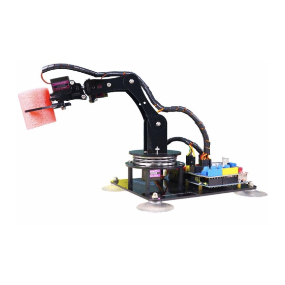
- Page 9 Today Adeept recommends a robotic learning kit to learn how to assemble a robotic arm and learn how to write the code to control the robotic arm to perform the specific motions. We provide a completed using method for learning Arduino and Processing write PC software and send motion commands to the robotic arm with Processing;...
- Page 10 The following figure shows that we control the robotic arm to write and draw through the mouse with serial communication.
- Page 11 We have added the learning and memory function to the robotic arm. We let the robotic arm to record the manually controlled mechanical movements we made, and the robotic arm can learn repeatedly, such as repeat moving the object, repeat drawing...
- Page 12 Introduction of Adeept Arm Drive Board The Adeept Arm Drive Board development board is the main component of the robotic arm. Similar to the Arduino UNO development board, it is also an easy-to-use open source electronic prototyping platform, including the hardware part and the software part (Arduino IDE).
- Page 13 Potentiometer button has five buttons: A0, A1, A2, A3, and A6. By rotating these buttons, you can control the movement of the robotic arm. In the following courses, we will combine the application of various components to further learn the practical application of the Adeept Arm Drive Board development board.
- Page 14 Lesson 0 Building the Arduino Development Environment 1. Arduino development language Arduino uses C/C++ to write programs, so before learning Arduino, you need to master the C/C++ language. Although C++ is compatible with the C language, these are two different languages. C is a process-oriented programming language, and C++ is an object-oriented programming language.
- Page 15 and loop() are used instead. 3. The construction of the Arduino development environment The IDE of the Arduino development environment can be downloaded from the official website. download address Arduino https://store.arduino.cc/usa/ (1) Install Arduino IDE under Windows We will teach you how to download and install: 1.Open Google Chrome...
- Page 16 3. We click the installation package of Windows ZIP file for non admin install.After the interface jumps, we select JUST DOWNLOAD.And then start the download. The download status will be displayed in the lower left of Google Chrome.Then we wait for the download to complete.
- Page 17 4.After the download is complete, open the folder.There are downloaded compressed installation files: arduino-1.8.12-windows.zip 5. Double-click to open the file and unzip it.
- Page 18 6. The file arduino-1.8.12 appears after decompression.As shown follows; 7. Open the arduino-1.8.12 folder and double-click arduino.exe to open the software. 8. The interface will show as follows after the Arduino software is opened, indicating that our software has been downloaded and installed successfully.
- Page 19 4. Introduction of Arduino software interface The following figure is the interface introduction of Arduino software...
- Page 20 (1)Menu bar Menu bar contains File, Edit, Sketch, Tools and Help. (1) "File" can operate new file, open file, save file, close file, save, etc. For the Examples, you can check the official sample program. (2) "Edit" has the functions for the program code of editing, copying and pasting, commenting, indenting,searching, etc.
- Page 21 written project. The Include Library can load the library. After selecting the library file in the list, the relevant header files are automatically added in the code editing area.
- Page 22 (4) Board and Port are often used in "Tools". Board can choose different development boards. Our course uses Arduino Uno development board, so we need to choose Arduino Uno. The list contains many Arduino development board models.We choose the corresponding ones according to the model.
- Page 23 Port can set the port used by Arduino IDE to download the program, that is, the port number of the development board connected to the computer. The port display of each computer is different. When we use the Arduino Uno to connect to the computer, it displays the COM3 port number.
- Page 24 Button bar includes functions of Verifying,Uploading,Building New,Opening and Saving. (1)Verify : Checking and compilation. This button is used to check the correctness of your "syntax" or code. If your code has any syntax errors or undefined variables, an error message will appear at the bottom of the IDE screen. At the same time, the line of error code will be marked with a red background color for easy modification.
- Page 25 5.Connecting the Adeept Arm Drive Board and the computer (1)Connecting the and the computer Adeept Arm Drive Board You need to use USB Cable to connect the to the Adeept Arm Drive Board computer.As shown below: (2) Select the Arduino Uno development board in Tools Open Arduino IDE under Tools—>Board.Select Arduino UNO in the list.
- Page 26 Adeept: AdeeptRoboticArmforArduinoV3_5, find the 01 Software Package folder, and open the Adeept driver folder. If you are using a Windows system, you can directly double-click to open CH341SER_Windows.EXE, install corresponding driver according to the computer operating system. 3. Click INSTALL.Wait for the installation to succeed.And click OK.
- Page 27 4.Now you will find the Arduino serial port is accessible (different computer configuration has different serial port).It means that the Arduino UNO development...
- Page 28 board has been successfully connected to the computer. You will need to pay attention to this connection step in the following course. 6.The solution for situation that Arduino IDE cannot be opened When opening the Arduino IDE, you will suddenly encounter a situation that it cannot be opened.
- Page 29 need find Arduino15 folder \Users\ASUS\AppData\Local\Arduino15 directory of the C drive.As shown below: You need to delete the package_index.json file, and then reopen the Arduino IDE. 7、Download Processing Processing is a revolutionary and forward-looking new computer language. Its concept is to introduce programming languages in the environment of electronic art and introduce the concept of electronic art to programmers.
- Page 30 2. Click Download Processing, as shown below: 3.The operating system we choose to use here is windows 64-bit, select "Windows 64-bit".
- Page 31 4.When finish downloading, will compressed file "processing-3.5.4-windows64.zip". 5.After extracting this file, you can get the following file, just click to run processing, it can be run directly without installation. 6.The interface is as follows after the Processing runs...
- Page 32 7.Let's write a simple code that implements the following functions "Change the variable to create a moving line. When the line moves out of the window edge, the variable becomes 0 and the line goes back to the bottom of the screen 8.Click “Run”.
- Page 33 9.Running effect is as follow.
- Page 34 8. Configuring the "libraries" folder of the Arduino Before using Adeept Robotic Arm, you need to configure the "libraries" folder under the downloaded Arduino IDE directory. First, need find user folder provided Adeept: AdeeptRoboticArmforArduinoV3_5, and find the "libraries" folder under the 01 Software Package folder, as shown below: Open the "libraries"...
- Page 35 You need to copy all files to the "libraries" under the Arduino IDE installation directory, as shown in the figure below: Paste the three folders in "libraries". As shown below:...
- Page 36 In this lesson, we will learn how to read the data of the potentiometer and convert the data into an angle. 1.1 Components used in this course Components Quantity Picture Adeept Arm Drive Board Micro USB Cable 1.2 Introduction of Potentiometer Potentiometer The potentiometer is a resistance element with three terminals and the resistance value can be adjusted according to a certain change law, which is equivalent to a variable resistor.
- Page 37 fixed contact. Potentiometer can be used to adjust the voltage and current. Our course uses a rotary potentiometer. Its structure is as shown in the figure below. By rotating the knob, the position of pin 2 is changed, thereby changing the resistance value from pin 2 to both ends.
- Page 38 1.Open the Arduino IDE software, as shown below: 2. In the Tools toolbar, find Board and select Arduino Uno, as shown below: 3.In the Tools toolbar, find “Port” and Select the port number of The Adeept Arm Drive Board , as shown below:...
- Page 39 4.Click Open in the File drop-down menu: 5.Find the folder AdeeptRoboticArmforArduinoV3_5 that we provide to the user. Open the folder 02 Course Code in it. Enter the Lesson 1 potentiometer directory. Select potentiometer.ino. This file is the code program we need in this course. Then click Open.
- Page 40 6.After opening, click to upload the code program to the Arduino UNO. If there is no error warning in the console below, it means that the Upload is successful. 7. After successfully running the program, we need to observe the value of the potentiometer by opening the serial monitor and click , as shown in the figure below:...
- Page 41 Then open the serial monitor, you need to modify the displayed bit rate and the bit rate set in the code to 115200, so that the display will not appear garbled. You can observe the data changes corresponding to each button by rotating the buttons of A0, A1, A2, A3, and A6.
- Page 42 1.4.2 Learning the code program of this lesson Initialize potentiometers A0, A1, A2, A3, A6. Initialize the serial monitor. Convert the value of 1023 to 180 proportionally, and then print out the converted data to the serial monitor.
- Page 43 In this lesson, we will learn how to control the Servo. 2.1Components used in this course Components Quantity Picture Adeept Arm Drive Board Micro USB Cable Servo 2.2 The introduction of the Servo 2.2.1 Servo Servo motor refers to the engine that controls mechanical component operation in the servo system.
- Page 44 In this way, it is possible to precisely control the rotation of the motor, thereby achieving precise positioning. Adeept Arm Drive Board sends a PWM signal to a servomotor, which is then processed by an IC on the circuit board to calculate the rotation direction of the drive motor, which is then transmitted through a reduction gear to the swing arm.
- Page 45 2.2.3 The principle of write () function In the program, we use the write() function to control the rotation of the servo. For standard servos, the write() function will rotate the servo axis to the corresponding angular position. For the continuous rotation type of servo, the write() function can set the rotation speed of the servo (0 indicates that the servo rotates at full speed in one direction, 180 indicates that the servo rotates at full speed in another direction, and 90 indicates that the servo is stationary.
- Page 46 2.3Wiring diagram (Circuit diagram) Connect Servo to the servo port on the Adeept Arm Drive Board, as shown below: 2.4 How to control Servo 2.4.1Compile and run the code program of this course...
- Page 47 1.Open the Arduino IDE software, as shown below: 2. In the Tools toolbar, find Board and select Arduino Uno, as shown below: 3.In the Tools toolbar, find “Port” and Select the port number of The Adeept Arm Drive Board , as shown below:...
- Page 48 5.Find the folder AdeeptRoboticArmforArduinoV3_5 that we provide to the user. Open the folder 02 Course Code in it. Enter the Lesson 2 servo directory. Select servo.ino. This file is the code program we need in this course. Then click Open. 6.After opening, click to upload the code program to the Arduino UNO.
- Page 49 7. After successfully running the program, you will observe the movement of the servo. 2.4.2 Learning the code program of this lesson Create servo object to control a servo. In the setup() function, attach the servo on pin 9 to servo object; back to 0 degrees; wait for a second.
- Page 50 OLED Screen clearly, and the power consumption is relatively low. When using the OLED Screen, you need to connect it to the OLED interface on the Adeept Arm Drive Board.
- Page 51 3.3 Wiring diagram (Circuit diagram) You need to connect it to the OLED interface on the Adeept Arm Drive Board.As shown below: 3.4 How to display text on the OLED screen 3.4.1 Compile and run the code program of this course...
- Page 52 1.Open the Arduino IDE software, as shown below: 2. In the Tools toolbar, find Board and select Arduino Uno, as shown below: 3.In the Tools toolbar, find “Port” and Select the port number of The Adeept Arm Drive Board , as shown below:...
- Page 53 After the above practical operation, you must be very curious to know how we use C language to program on the Adeept Arm Drive Board to display text on the OLED screen. Below we will introduce how the main code program is implemented.
- Page 54 In the loop() function, set the display font size with setTextSize(1); setCursor(30,30) sets the position of the text displayed on the OLED screen, and print("TEST") prints out the text information that needs to be displayed.
- Page 55 The Adeept Arm Drive Board has its own EEPROM, and its memory size is 1K. Arduino IDE comes with EEPROM usage method. The Arduino library has prepared EEPROM library for us.You can directly call EEPROM.h in the code when...
- Page 56 1.Open the Arduino IDE software, as shown below: 2. In the Tools toolbar, find Board and select Arduino Uno, as shown below: 3.In the Tools toolbar, find “Port” and Select the port number of The Adeept Arm Drive Board , as shown below:...
- Page 57 4.Click Open in the File drop-down menu: 5.Find the folder AdeeptRoboticArmforArduinoV3_5 that we provide to the user. Open the folder 02 Course Code in it. Enter the Lesson 4 EEPROM directory. Select EEPROM.ino. This file is the code program we need in this course. Then click Open.
- Page 58 6.After opening, click to upload the code program to the Arduino UNO. If there is no error warning in the console below, it means that the Upload is successful. 7. After successfully running the program, we need to observe the value of the potentiometer by opening the serial monitor and click , as shown in the figure below:...
- Page 59 4.4.2 Learning the code program of this lesson After the above practical operation, you must be very curious to know how we use C language to program on the Adeept Arm Drive Board to save data with...
- Page 60 EEPROM. Below we will introduce how the main code program is implemented. In the setup() function, first initialize the serial monitor, EEPROM.read(5) reads the data, and judges by if, if the read data is 2, then it is saved successfully.
- Page 61 Lesson 5 Servo 90 degree adjustment Before assembling the robotic arm, we first need to adjust the 5 servos of the robotic arm by 90 degrees. 5.1 Components used in this course Components Quantity Picture Adeept Arm Drive Board Micro USB Cable Servo 5.2 Wiring diagram (Circuit diagram)
- Page 62 5.3 Upload the Servo90.ino 1.Open the Arduino IDE software, as shown below: 2. In the Tools toolbar, find Board and select Arduino Uno, as shown below:...
- Page 63 3.In the Tools toolbar, find “Port” and Select the port number of The Adeept Arm Drive Board , as shown below: 4.Click Open in the File drop-down menu: 5.Find the folder AdeeptRoboticArmforArduinoV3_5 that we provide to the user. Open the folder 02 Course Code in it. Enter the Lesson 5 Servo90 directory. Select...
- Page 64 90 degrees. 【Note】: For the adjusted servos, it is forbidden to rotate them when assembling the robotic arm, otherwise it will cause errors in the assembly of the robotic arm. 8.Now you can proceed to the assembly operation of Lesson 6...
- Page 65 Lesson 6 How to Assemble the Robotic Arm 6.1 Pedestal Assembly 1.Fix four Sucking Discs on the four corners of A01 Cap Nut x4 Assemble the following components A01 x1 Sucking Disc x4 Effect diagram after assembling...
- Page 66 2.Fix OLED to drive M2.5*11 cooper stands x2 M2*18 Screw x2 OLED M2 Nut x2 Effect diagram after assembling Oled should be correct with the robot Arm drive Hat connection, the screen should be placed in the driver board...
- Page 67 3.Fix 18650x2 Battery Holder to A01. Assemble the following components M3*10 Countersunk Head Screw x2 The wires of 18650x2 Battery Holder are near inside. 18650x2 Battery Holder x1 M3 Nut x2 Effect diagram after assembling...
- Page 68 4.Fix four M3*6 Copper Standoffs to A01 Assemble the following components M3*15 nylon Standoff x4 M3*8 Screw x4 Effect diagram after assembling...
- Page 69 5.Fix Adeept UNO R3 Board to M3*6 Copper Standoff. Assemble the following components M3*5 Screw x4 Adeept UNO R3 Board x1 Effect diagram after assembling 6. Fix four M3*30 Nylon Standoffs to A01...
- Page 70 Assemble the following components M3*30 Nylon Standoff x4 M3*8 Screw x4 Effect diagram after assembling...
- Page 71 Once the circuit is connected, load your 18650 battery into 18650x2 Battery Holder and turn on the switch on the Adeept Arm Drive Board. At this point, the servo will automatically rotate to the initial state, then turn off the power and remove each servo.
- Page 72 6.1.2 Install and Remove Batterries Take out 2 ribbons and 2 batteries. Roll one end of the ribbon to let through a battery and fix. Insert the batteries into the rings-ribbon closer to the anode. Install the batteries into the holder based on the pole. To remove the batteries, just pull the ribbon and take them out.
- Page 73 If you have already adjusted the steering gear to 90 degrees according to Lesson 5, then you don’t need to adjust it anymore, please proceed to the next part ) Connect five servos to the Adeept Arm Drive Board. For convenience to read, only one end of the servo power cable is shown here.
- Page 74 SERVO of number...
- Page 75 2. Fix a debugged servo to A02 and A03 Assemble the following components For convenience to read, A02 is displayed in green, M2*10 Screw x1 and the color of all acrylic sheets is subject to the A03 x1 actual product. A02 x1 Servo x1 M2 Nut x1...
- Page 76 3. Then fix A02 to M3*30 Nylon Standoff Assemble the following components M3*8 Screw x4 M3*30 Nylon Standoff Effect diagram after assembling...
- Page 77 4.Assemble 51108 Bearing. Assemble the following components Put 51108 Bearing on 51108 Bearing x1 A03 as shown in the figure. Effect diagram after assembling...
- Page 78 5.Take a rocker arm as in the illustration and connect it to A04 Assemble the following components Effect diagram after assembling Rocker arm x1 Note that the center of the rocker arm is aligned with the center of the A04. A04 x1 Screw the self-tapping screw just into the rocker arm.
- Page 79 8. Then fix one end of A07 to the servo on A06. First install the rocker arm on the A07 into the servo. When installing, the mounting hole of the rocker arm should be aligned with the round hole on the A07. Install it at the angle shown below.
- Page 80 9. Fix a debugged servo to A10. Assemble the following components Effect diagram after assembling M2*10 Screw x2 A10 x1 A09 x1 Servo x1 M2 Nut x2 10. Then fix the other end of the A07 to the servo on the A10. First install the rocker arm on the A07 into the servo.
- Page 81 11. Then fix A06 to A04. Assemble the following components M3 Nut x1 M3*12 Screw x1 Effect diagram after assembling...
- Page 82 12.Connect A05 with A08 and A11. Assemble the following components M3 Lock Nut x2 A08 x1 A11 x1 A05 x1 M3*12 Screw x2 Do not tighten between M3 Lock Nut and M3*12 Screw. Allow rotation between A05 and A08, also A08 and A11. Effect diagram after assembling...
- Page 83 13. Fix A05 to A04. Assemble the following components M3 Nut x1 M3*12 Screw x1 Effect diagram after assembling...
- Page 84 14. Fix the rocker arm under A04 with the servo on A02. The angle when the rocker arm is installed into the servo is as shown below. Assemble the following components Rocker arm Servo...
- Page 85 Effect diagram after assembling Then fix the rocker arm to the servo with the fixing screw packaged with servo. Assemble the following components Fixing screw packaged with servo x1...
- Page 86 Effect diagram after assembling...
- Page 87 6.2 Play 1 Fix A18 between A10 and A11. Assemble the following components M3 Nut x2 M3*8 Screw x2 A18 x1 Choose A18 or A19 according to the actual size of the pen. Effect diagram after assembling...
- Page 88 Fix the pen with A18. Assemble the following components Pen x1 M3 Nut x1 M3*12 Screw Effect diagram after assembling The tip of the pen should be 60 mm away from A18.
- Page 89 6.3 Play 2 1. Fix one M3*8 Copper Standoff to A15. Assemble the following components Effect diagram after assembling M3*8 Copper Standoff Install it in strict accordance with the M3*18 Screw position shown in the figure. Do not mount the M3*8 Copper Standoff on the other side of the A15.
- Page 90 3. Fix one rocker arm of the servo to A17. Assemble the following components Effect diagram after assembling Rocker arm x1 A17 x1 Self-tapping screw packaged with servo 4. Assemble A16 and A17. Install A16 and A17 as shown below. Assemble the following components Effect diagram after assembling M2.5*7 Screw x1...
- Page 91 5.Fix a debugged servo to A12. Assemble the following components Effect diagram after assembling M2*10 Screw x2 A12 x1 Servo x1 M2 Nut 6. Fix a rocker arm to A13. Assemble the following components Effect diagram after assembling Rocker arm x1 A13 x1 Self-tapping screw packaged with servo...
- Page 92 7. Fix the rocker arm on the A13 to the servo on the A12. Install as shown below. Assemble the following components Effect diagram after assembling Fixing screw packaged with servo x1...
- Page 93 8. Fix one A14 with two M3*40 Nylon Standoffs. Assemble the following components Effect diagram after assembling M3*8 Screw x2 A14 x1 M3*40 Nylon Standoff x2 9. Complete assembly of the clamp section. Assemble the following components A14 x1 M3*8 5Screw x2 Effect diagram after assembling...
- Page 94 Install the clamp section on the robotic arm. Assemble the following components M3*8 Screw x2 M3*30 Nylon Standoff x1 Effect diagram after assembling Servo5 Servo4 Servo3 Servo2 Servo1 Number each servo to prepare for the circuit connection.
- Page 95 66.5mm 13mm 70mm 65mm 40mm 60mm...
- Page 96 6.4 Circuit Connection Connection of each devices for the robotic arm: Insert the servo numbered in the last step into the port here correspondently. The color of the three power cables of the servo corresponds to the port color (as shown on the left).
- Page 97 Before starting to exert the function, we need to test whether there are problems with the assembly of the robotic arm.When you connect all the servos mounted on the robot arm to the Adeept Arm Drive Board correctly and turn on the power switch...
- Page 98 【If your robot arm is assembled and turned on, it is not what it looks like in the picture above, then how do you adjust it?】 1.First, you need to re-download the code used in lesson 5: Servo90.ino. Observe if the robot arm is close to the one in the picture above. 2.If it does not work, then you need to manually disassemble the robot arm for adjustment, is to operate with the power on, generally you just need to manually adjust the A07 section in the figure below, remove it, and then connect the upper and...
- Page 100 Lesson 7 GUI application control mode In this lesson, you will learn how to control the movement of the robotic arm with the GUI application. 7.1 Downloading and installing Python https://www.python.org/downloads/ (1) Log in to the official website by browser: (2) Click the "Download Python 3.8.3"...
- Page 101 (4) Select the "Add Python 3.8 to PATH" option: (5) Then click "Install Now" to install. (6) Wait for the Python installation to complete and click "Close" to close.
- Page 102 7.2 Installing pySerial pySerial encapsulates the serial communication module,supporting Linux, Windows, BSD (may support all operating systems that support POSIX), Jython (Java) and IconPython (.NET and Mono). The pyserial module encapsulates access to the serial port.The port number starts from 0 by default.There is no need to know the port name in the program.
- Page 103 Before downloading and installing, you need to connect the Adeept Arm Drive Board development board to your computer. (1) Press Win+R shortcut key to open CMD under Windows 10: (2) Click "OK": (3) Enter the command in the window: pip install pyserial...
- Page 104 7.3 Opening the GUI interface (1) Enter the folder "AdeeptRoboticArmforArduinoV3_5" → "01 Software Package" → "block_py" provided by Adeept for users, and find this file: "block_py.ino". (2) Then right-click the file: "block_py.ino". Select "Open with" → "Choose another app". (3) Click "More apps", and then click "OK".
- Page 105 (4) Use the mouse to slide down, click "Look for annother app on this PC", and then click"OK". (5) Find the Arduino software on the Desktop or where you installed the Arduino software, select it, and finally click "Open".
- Page 106 (6) At this time, the Arduino software opens the file "block_py.ino". (7) First select the Arduino development board as UNO version with Tools.
- Page 107 (8) Then continue to use Tools to select the port “Port” of the Adeept Arm Drive Board connected to the computer. (9) Click the Upload button to download the code program to the Arduino development board.
- Page 108 (10) Find the folder AdeeptRoboticArmforArduinoV3_5"→"01 Software Package"→"websocket", find this file: "servosGUI.py". (11) Double-click to open this file: servosGUI.py...
- Page 109 Port in the Arduino IDE in the Port input field. For example, the Port connected to the Arduino IDE is COM5, then you enter COM5, and then click Connect. After successfully connecting, there will be a prompt message in the upper left corner: "COM5: Succes". 7.4 Controlling the robotic arm with the GUI interface...
- Page 110 2. When you need to control the robotic arm, you can slide the slider corresponding to the servo in the left area to control the movement of the robotic arm. When a certain position is slipped, a data will be displayed on the slider, this data...
- Page 112 Lesson 8 GwBlock graphical control mode We creatively provide users with Arduino graphical programming tools-GwBlock. Using graphical program instruction blocks to achieve control of Arduino with the Web page. Compared with the traditional pure character interface code programming platform, graphical programming is more conducive to learners who have not mastered C/C++.
- Page 113 (3) Open the downloaded file, double-click to open it to install: (4) Select the "Add Python 3.8 to PATH" option: (5) Then click "Install Now" to install.
- Page 114 (6) Wait for the Python installation to complete and click "Close" to close. 8.2 Installing pySerial and connecting GwBlock graphical editor...
- Page 115 (windows), JavaComm (Jython). POSIX (Linux, BSD) only depends on the Python standard library. Before downloading and installing, you need to connect the Adeept Arm Drive Board development board to your computer. (1) Press Win+R shortcut key to open CMD under Windows 10:...
- Page 116 Press the Enter and wait for the installation to complete. (4) Open the folder "AdeeptRoboticArmforArduinoV3_5" provided by Adeept to the user → “01 Software Package”→"block_py" and find this file: "block_py.ino". (5) Then right-click the file: "block_py.ino". Select "Open with" → "Choose...
- Page 117 (6) Click "More apps", then click "OK". (7) Slide the mouse down, click "Look for annother app on this PC", and then click "OK".
- Page 118 (8) Find the Arduino software on Desktop or the place where you installed the Arduino software, select it and click "Open". (9) Then the Arduino software opens the file "block_py.ino".
- Page 119 (10) First select the Arduino development board as UNO version with Tools. (11) Then continue to select the "Port" of the connected to Adeept Arm Drive Board the computer with Tools.
- Page 120 (13) We re-use the Arduino software to open the "block_py.ino" file, and then click the Upload button again to download the code program to the Adeept Arm Drive Board development board. After the download is successful, the following picture is shown:...
- Page 121 (14) Find the folder AdeeptRoboticArmforArduinoV3_5"→"01 Software Package"→"websocket", find this file: "GUI info v1.0.py". (15) Double-click to open this file: GUI info v1.0.py...
- Page 122 IP address, which will be used later: 192.168.3.69 (17) In the input box, enter the port we set in step (11).Everyone's port is different.The port of my Adeept Arm Drive Board development board is: COM4. After entering, click the Connect button.
- Page 123 IP address we recorded in step (16), as shown below, and then click the Connecting button. (20) After the connection is successful, a green "connected" will appear in the lower left corner of the interface, indicating that the connection with the Adeept Arm Drive Board is successful.
- Page 124 In the following cases, you need to reconnect to the GwBlock graphical editor: [1] When you close the GwBlock editor. [2] When you close the Adeept Arduino Robot window. [3] When you restart the computer. [4] When you log in to the GwBlock website again.
- Page 125 (4) Double-click to open this block_py.ino file (use Arduino to open!), as shown below: (5) Select COM4 as the port of Adeept Arm Drive Board in Tools in the toolbar of Arduino IDE, and click the icon in the upper left corner to download the...
- Page 126 as follows: (6)Next, open the folder we provide to the user: AdeeptRoboticArmforArduinoV3_5 Then open 01 Software Package.As shown below: (7) Open the websocket folder.There is a file inside: GUI info v1.0.py. (8) Double-click to open the GUI info v1.0.py file, and the following picture will appear after opening: (9) After opening the file, the following interface will appear.
- Page 127 (10) Enter the Arduino software download program in the input box of Adeept Arduino Robot.The connected port number: COM4. Click the Connect button.As shown below: (11)Enter the URL of the GwBlock graphical editor in the browser: http://www.adeept.com/gwblock/?hd_mo=uno_r3. After successfully entering the website, the interface is as follows:...
- Page 128 (12)Click the "Connecting device" button in the upper right corner. It will show as below: (13) In the pop-up box, enter the IP address in step (9): 192.168.3.69. And then click the Connecting button, as shown below: (14) After a successful connection, as shown below, a green connected prompt will appear in the lower left corner.
- Page 129 8.4 Get to know about Arduino's graphical editor GwBlock The functions of the buttons on the main interface of the GwBlock editor will be described in detail below according to the function numbers in the picture. As shown below: 【1】 Blocks: Click this button to switch to the programming mode of the graphical code block.
- Page 130 【2】Python: Click this button to display the edited graphical code block in the form of Python code. 【 3 】 Connecting device: Click this button to connect to the Arduino development board, which requires you to enter the IP address. 【4】...
- Page 131 button to the right of English. Currently, we only support English and Simplified Chinese. 【 6 】 is the icon of the Arduino UNO development board, indicating that it is currently in the Arduino programming mode. 【7】 is the camera button, which is gray in the initial off state: When you click it, the camera will turn red: ,indicating that the camera is on.
- Page 132 (2) After the device is successfully connected, the display is as follows: 【11】is a code trash, you can drag and drop the code instruction block to delete it. 8.5 Controlling the movement of the robotic arm with GwBlock graphical programming 8.5.1 Run the program for this lesson...
- Page 133 You need to make a modification in the lower right corner and select All Files, as shown below: 3. Then the folder will be displayed. As shown below: 4. Find the user folder AdeeptRoboticArmforArduinoV3_5→02 Course Code→Lesson 8 block of Adeept, as shown below:...
- Page 134 5. Open the Lesson 8 block folder and select the "main.gwblock" file. This file is our graphical code program for this lesson. Click "Open" in the lower right corner, as shown below: 6. Click OK, as shown below: 7. Click the button in the upper right corner, after successfully running the...
- Page 135 0~180°; When you rotate the A2 button, by controlling the rotation of the D3 servo, you can control the forearm part of the robotic arm to swing up and down, with a swing range of 0~180°;...
- Page 136 In the GwBlock graphical editor, all code programs are executed from Initialize the servo. Read the data of the potentiometer button. Convert the read potentiometer analog data. Control the movement of each servo respectively.
- Page 138 1.Open the Arduino IDE software, as shown below: 2. In the Tools toolbar, find Board and select Arduino Uno, as shown below: 3.In the Tools toolbar, find “Port” and Select the port number of The Adeept Arm Drive Board , as shown below:...
- Page 139 4.Click Open in the File drop-down menu: 5.Find the folder AdeeptRoboticArmforArduinoV3_5 that we provide to the user. Open the folder 02 Course Code in it. Enter the Lesson 9 Potentiometer_control directory. Select Potentiometer_control.ino. This file is the code program we need in this course.
- Page 140 Board. If there is no error warning in the console below, it means that the Upload is successful. 7.Next, unplug the USB cable connected to the robotic arm. Note: Do not turn on the power of the arm after downloading the program. Adjust the four potentiometers...
- Page 141 8.hen manually adjust the robotic arm to the position shown below: Gently support the robotic arm with your hand to prevent swinging arm. Turn on the power, and then rotate the four potentiometers on the driver board to control the...
- Page 142 arm to clamp and carry objects. The rotation angle of Servo5 is set in the code. 9.2 How to control the robot arm by potentiometer...
- Page 143 【Specific function descriptions】: ▲The potentiometer A0 on the driver board controls the movement of servo 1, range from 0 to 180 degrees. ▲The potentiometer A1 on the driver board controls the movement of servo 2, range from 0 to 180 degrees. ▲The potentiometer A2 on the driver board controls the movement of servo 3, range from 0 to 180 degrees.
- Page 144 1.Potentiometer control mode is not very precise, there will be some delay, so it is best to turn the potentiometer button slowly when using. 2.The power of the tiller is very small, and can only clamp and carry relatively light objects. 3.Robotic arm works better with a fully charged battery.
- Page 145 1.Open the Arduino IDE software, as shown below: 2. In the Tools toolbar, find Board and select Arduino Uno, as shown below: 3.In the Tools toolbar, find “Port” and Select the port number of The Adeept Arm Drive Board , as shown below:...
- Page 146 4.Click Open in the File drop-down menu: 5.Find the folder AdeeptRoboticArmforArduinoV3_5 that we provide to the user. Open the folder 02 Course Code in it. Enter the Lesson 10 Learning directory. Select Learning.ino. This file is the code program we need in this course. Then click Open.
- Page 147 You will see the working status of the current situation and the number of the remaining motions the robotic arm needs to be record display on the OLED.At this point, the robot arm goes into learning mode.
- Page 148 10.2 How to start the learning mode of robotic arm 10.2.1 Introduction to Learning Mode In the learning mode, the robot arm can record different motion states or actions (up to 200 can be recorded, the recorded actions can be written into EEPROM), After re-powering, press the “BUTTON”...
- Page 149 (4) Press the "RESET" button on the Adeept Arm Drive Board to restart the robotic arm to exit the automatic motion mode. At this time, the robotic arm is in the learning mode, so you can continue to repeat step 1 to re-record other motion states or actions.
- Page 150 1.Use the Arduino IDE to open the program "Learning.ino" of this lesson (in the folder "Lesson 10 Learning"): 2.Find the 37th line of code, where "number = 10" means that the robotic arm can record up to 10 motion states or actions. You can modify the number to the number you want to record, and the maximum should not exceed 200.
- Page 151 Lesson 11 Processing controls robotic arm In this course, we will learn how to use Processing software to control robotic arms. 11.1 Download Processing Processing is a revolutionary and forward-looking new computer language. Its concept is to introduce programming languages in the environment of electronic art and introduce the concept of electronic art to programmers.
- Page 152 2. Click Download Processing, as shown below: 3.The operating system we choose to use here is windows 64-bit, select "Windows 64-bit". 4.When finish downloading, will compressed file "processing-3.5.4-windows64.zip".
- Page 153 5.After extracting this file, you can get the following file, just click to run processing, it can be run directly without installation. 6.The interface is as follows after the Processing runs...
- Page 154 7.the library file controlP5 needs to be added.
- Page 155 Then search controlP5(If you do not find it in the list, please close this window, reopen it, and search again).Finally click Install 8.Let's write a simple code that implements the following functions "Change the variable to create a moving line. When the line moves out of the window edge, the variable becomes 0 and the line goes back to the bottom of the screen...
- Page 156 9.Click “Run”. 10.Running effect is as follow.
- Page 157 11.2 Upload the AdeeptArmRobot.ino The AdeeptArmRobot.ino is a program to control the robotic arm servo. 1.Open the Arduino IDE software, as shown below: 2. In the Tools toolbar, find Board and select Arduino Uno, as shown below:...
- Page 158 3.In the Tools toolbar, find “Port” and Select the port number of The Adeept Arm Drive Board , as shown below: 4.Click Open in the File drop-down menu:...
- Page 159 Then click Open. 6.After opening, click to upload the code program to the Adeept Arm Drive Board. If there is no error warning in the console below, it means that the Upload is...
- Page 160 7.After downloading, close AdeeptArmRobot.ino 8.Note that the arm is still connected to the computer with the USB cable. Rotate the arm to the position as shown in the figure below(Manually remove and adjust without power supply) 11.3 Run the ProcessingArmRobot.pde Note that the arm is still connected to the computer with the USB cable.
- Page 161 2. Click Open in the File drop-down menu:: 3.Find the folder AdeeptRoboticArmforArduinoV3_5 that we provide to the user. Open folder Course Code Enter Lesson Processing→ProcessingArmRobot directory. Select ProcessingArmRobot.pde. This file is the code program we need in this course. Then click Open. 4.After opening, Click "...
- Page 162 5.The interface of successful running is as below,Provides two ways to control the robotic arm:keyboard and mouse. 6.Click "keyboard" the following interface will appear. Next, press the corresponding button on the keyboard to control the arm. 1."Q" and "W" control servo5 (Gripper), The “Q” button is to control the gripper to open, the “W”...
- Page 163 7.Click "mouse" and the following interface will appear.click the corresponding button, the robotic arm will make the corresponding movement. 1."Gripper+" and "Gripper-" control the servo5, 2."Rotate+" and "Rotate-" control the servo4, 3."Elbow+" and "Elbow-" control the servo3, 4."Shoulder+" and "Shoulder-" control the servo2,...
- Page 165 In this lesson, we will introduce the Imitation function mode of the robot arm. 12.1 Prepare 【Refit】: You need to transform the robotic arm into the structure of the picture on the right: Replace the claws of the robotic arm with pens. 【Circuit】:...
- Page 166 Connect Servo1, Servo2 and Servo3 on the robotic arm to Servo1 (D9), Servo2 (D6) and Servo3 (D5) ports on the Adeept Arm Drive Board.
- Page 167 12.2 Upload the AdeeptSimulation.ino 1.Open the Arduino IDE software, as shown below: 2. In the Tools toolbar, find Board and select Arduino Uno, as shown below:...
- Page 168 3.In the Tools toolbar, find “Port” and Select the port number of The Adeept Arm Drive Board , as shown below: 4.Click Open in the File drop-down menu:...
- Page 169 Select AdeeptSimulation.ino. This file is the code program we need in this course. Then click Open. 6.After opening, click to upload the code program to the Adeept Arm Drive Board. If there is no error warning in the console below, it means that the Upload is successful.
- Page 170 You will see the working status of the current situation and the number of the remaining motions the robotic arm needs to be record display on the OLED.At this point, the robot arm goes into imitation mode.
- Page 171 (4) Press the "RESET" button on the Adeept Arm Drive Board to restart the robotic arm to exit the automatic motion mode. At this time, the robotic arm is in the...
- Page 172 (5). After the robotic arm is re-powered or restarted, press the "BUTTON" button for more than 8 seconds to enter the automatic motion mode, and the robotic arm will automatically run the motion track or action recorded last time.
- Page 173 2.Find the 15th line of code, where "number = 3" means that the robotic arm can record up to 3 motion track or actions. You can modify the number to the number you want to record, and the maximum should not exceed 333.
- Page 174 1.Open the Arduino IDE software, as shown below: 2. In the Tools toolbar, find Board and select Arduino Uno, as shown below: 3.In the Tools toolbar, find “Port” and Select the port number of The Adeept Arm Drive Board , as shown below:...
- Page 175 4.Click Open in the File drop-down menu: 5.Find the folder AdeeptRoboticArmforArduinoV3_5 that we provide to the user. Open the folder 02 Course Code in it. Enter the Lesson 13 write and draw→WritingAndDrawing directory. Select WritingAndDrawing.ino. This file is the code program we need in this course. Then click Open.
- Page 176 6.After opening, click to upload the code program to the Adeept Arm Drive Board. If there is no error warning in the console below, it means that the Upload is successful. 7.After downloading, close WritingAndDrawing.ino 8.Note that the arm is still connected to the computer with the USB cable.Turn on the power supply.
- Page 177 2. Click Open in the File drop-down menu:: 3.Find the folder AdeeptRoboticArmforArduinoV3_5 that we provide to the user. Open the folder 02 Course Code in it. Enter the Lesson 13 write and draw→WritingAndDrawing directory. Select ProcessingWritingAndDrawing.pde. This file is the code program we need in this course. Then click Open.
- Page 178 4.After opening, Click " " to run the code, as shown below 5.Then click "Run" to run the control panel program, the following control interface will appear:...
- Page 179 7.Draw or write in the yellow area with the mouse, you will see that the robotic arm paints what we depict on the control panel on the paper. Note that due to errors in the servo, etc., the content depicted by the arm will be slightly biased. 8.Click the dots as shown below:...
- Page 180 10.After modifying the three parameters to make the tip of the pen reach to the paper (do not make the tip press against the paper), click "Run" to run the control panel program. The robotic arm will paint as you write or draw in the dark yellow area with the mouse.
Need help?
Do you have a question about the Robotic Arm and is the answer not in the manual?
Questions and answers