Table of Contents
Advertisement
Advertisement
Table of Contents

Related Manuals for ADEEPT ADA031


Summary of Contents for ADEEPT ADA031
- Page 1 www.adeept.com...
- Page 2 Please place and put the product gently. Do not smash or shock it. About Adeept is a technical service team of open source software and hardware. Dedicated to applying the Internet and the latest industrial technology in open source area, we strive to provide the best hardware support and software service for general makers and electronic enthusiasts around the world.
- Page 3 This user manual and code can be used for learning, DIY, refitting, etc., except for commercial purpose. The Adeept Company owns all rights of contents in the manual, including but not limited to texts, images, data, etc. Any distribution or printing should be implemented with the...
-
Page 4: Table Of Contents
1. Components List..........................1 1.1. Acrylic Plates........................1 1.2. Machinery Parts........................3 1.3. Electronic Parts........................4 1.4. Tools............................5 1.5. Self-prepared Parts.......................5 2.Introduction of Robotic Arm......................6 3.Arduino and Processing Environment Installation................8 4. Assembly............................21 4.1. Pedestal Assembly......................21 4.2. Install and Remove Batteries..................32 4.3. -
Page 5: Components List
1. Components List 1.1. Acrylic Plates 1pcs 1pcs 1pcs 1pcs 1pcs 1pcs 1pcs 1pcs... - Page 6 1pcs 3pcs 1pcs 1pcs 1pcs 2pcs 1pcs 1pcs 1pcs 1pcs 1pcs The acrylic plates are fragile, so please be careful when assembling them in case of breaking. The acrylic plate is covered with a layer of protective film. You need to remove it first.
-
Page 7: Machinery Parts
Screw www.adeept.com www.adeept.com www.adeept.com www.adeept.com www.adeept.com M3*10 M2*6 M3*6 M3*8 M3*30 Countersunk Copper Copper Copper Nylon Head Standoff Standoff Standoff Standoff Screw www.adeept.com www.adeept.com www.adeept.com www.adeept.com www.adeept.com M3*40 Nylon Standoff www.adeept.com 51108 Bearing Sucking disc component Cap Nut Sucking Disc... -
Page 8: Electronic Parts
1.3. Electronic Parts Adeept Arm Drive Board X1 Adeept UNO R3 Board X1 Adeept Touch Button X1 OLED X1 18650x2 Battery Holder X1 Servo X5 3-Pin Wire X1 4-Pin Wire X1 Servo Extension Cable X1 USB Cable X1... -
Page 9: Tools
1.4. Tools Cross Socket Wrench X1 Large Cross-head Screwdriver X1 Ribbon X1 Winding Pipe X1 1.5. Self-prepared Parts 18650 Battery X2 Pencil X1... -
Page 10: Introduction Of Robotic Arm
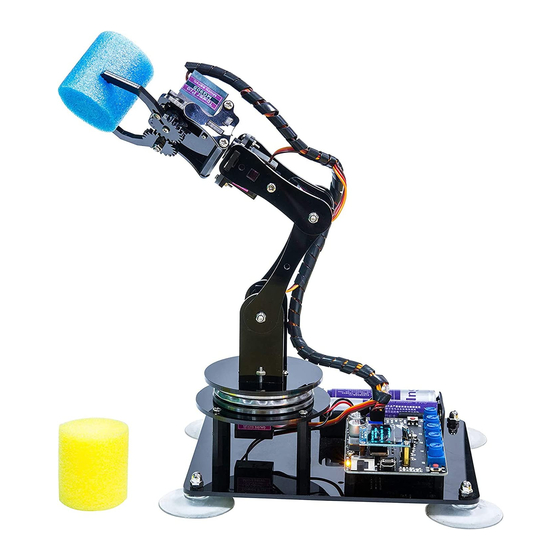
That is, the biggest advantage of the robotic arm is that normally it can repeat the same motion without feeling tired. Today Adeept recommends a robotic learning kit to learn how to assemble a robotic arm and learn how to write the code to control the robotic arm to perform the specific motions. - Page 11 The following figure shows that we control the robotic arm to write and draw through the mouse with serial communication. We have added the learning and memory function to the robotic arm. We let the robotic arm to record the manually controlled mechanical movements we made, and the robotic arm can learn repeatedly, such as repeat moving the object, repeat drawing the same graphic, repeat keyboard input and repeat turning book pages.
-
Page 12: Arduino And Processing Environment Installation
Installation More about building up Arduino development environment please check this video More learning videos please click on http://www.adeept.com/video/ Let's take the Windows 64-bit system as an example (the Arduino IDE also supports MAC and Linux). First open the browser and enter the URL https://www.arduino.cc/en/Main/Software and you will see the following interface. - Page 13 Run the downloaded file. Click “I Agree”. Click “Next”.
- Page 14 Leave the installation path as default, click "Install". Then enter the installation process, please wait. If the option pops up during the installation process, please select "Install".
- Page 15 When the installation is complete, click "Close". After the installation is complete, you can see the icon of the Arduino IDE on your computer desktop. Click to run Arduino, the following interface will appear.
- Page 16 Let's write a simple program that lights up the LEDs on the UNO board and lets them flash. Code: Next we connect the UNO to the computer with a USB cable. Open the system device manager, you will see the UNO port number is COM7. It may be...
- Page 17 Next, go back to the Arduino IDE interface and select the model of the control board. Click on "Tools" -> "Board" -> "Arduino/Genuino Uno", as shown below Next click “Tools”->”COM7(Arduino/Genuino Uno)”...
- Page 18 When finish selecting, upload the code to UNO by clicking "Upload". When the code is successfully downloaded to UNO, you can see the LED flashes.
- Page 19 More details about the download and usage of Processing, please click on this video More learning videos please click on http://www.adeept.com/video/ Open your browser and enter the URL www.processing.org Click on "Download Processing"...
- Page 20 The operating system we choose to use here is windows 64-bit, select "Windows 64-bit" When finish downloading, you will get a compressed file "processing-3.4-windows64.zip".
- Page 21 After extracting this file, you can get the following file, just click to run processing, it can be run directly without installation. The interface is as follows after the Processing runs...
- Page 22 Let's write a simple code that implements the following functions "Change the variable to create a moving line. When the line moves out of the window edge, the variable becomes 0 and the line goes back to the bottom of the screen."...
- Page 23 Click “Run”.
- Page 24 Running effect is as follow.
-
Page 25: Assembly
4. Assembly 4.1. Pedestal Assembly. 1. Connect the Adeept Touch Button to 3-Pin Wire. Assemble the following components Adeept Touch Button x1 3-Pin Wire x1 Effect diagram after assembling For convenience to read, 3-Pin Wire will be only shown the connector part in the following section. - Page 26 3. Fix four Sucking Discs on the four corners of A01. Assemble the following components Cap Nut x4 A01 x1 Sucking Disc x4 Effect diagram after assembling...
- Page 27 4. Fix two M2*6 Copper Standoffs to A01. Assemble the following components M2*6 Copper Standoff x2 M2*4 Screw x2 Effect diagram after assembling...
- Page 28 5. Fix Adeept Touch Button to M2*6 Copper Standoff. Assemble the following components M2*4 Screw x2 Adeept Touch Button Effect diagram after assembling...
- Page 29 6. Fix four M2*6 Copper Standoffs to A01. Assemble the following components M2*6 Copper Standoff x1 M2*4 Screw x4 Effect diagram after assembling...
- Page 30 7. Fix OLED to M2*6 Copper Standoff. Assemble the following components M2*4 Screw x4 OLED Effect diagram after assembling The wires of the OLED should be passed through from the edge of the hole above the A01.
- Page 31 8.Fix 18650x2 Battery Holder to A01. Assemble the following components M3*10 Countersunk Head Screw x2 18650x2 Battery Holder x1 The wires of 18650x2 Battery Holder are near outside. M3 Nut x2 Effect diagram after assembling...
- Page 32 9. Fix four M3*6 Copper Standoffs to A01. Assemble the following components M3*6 Copper Standoff x4 M3*5 Screw Effect diagram after assembling...
- Page 33 10. Fix Adeept UNO R3 Board to M3*6 Copper Standoff. Assemble the following components M3*5 Screw x4 Adeept UNO R3 Board x1 Effect diagram after assembling...
- Page 34 11.Insert Adeept Arm Drive Board into Adeept UNO R3 Board. Assemble the following components Adeept Arm Drive Board x1 Effect diagram after assembling...
- Page 35 12. Fix four M3*30 Nylon Standoffs to A01. Assemble the following components M3*30 Nylon Standoff x4 M3*8 Screw x4 Effect diagram after assembling...
-
Page 36: Install And Remove Batteries
4.2. Install and Remove Batteries Take out 2 ribbons and 2 batteries. Roll one end of the ribbon to let through a battery and fix. Insert the batteries into the rings-ribbon closer to the anode. Install the batteries into the holder based on the pole. -
Page 37: Turnplate And Rocker Arm Assembly
4.3. Turnplate and Rocker Arm Assembly 1. Servo debugging. Connect five servos to the Adeept Arm Drive Board. For convenience to read, only one end of the servo power cable is shown here. Connect the servos to Servo1, Servo2, Servo3, Servo4, and Servo5 on the Adeept Arm Drive Board. - Page 38 Once the circuit is connected, load your 18650 battery into 18650x2 Battery Holder and turn on the switch on the Adeept Arm Drive Board. At this point, the servo will automatically rotate to the initial state, then turn off the power and remove each servo.
- Page 39 2. Fix a debugged servo to A02 and A03. Assemble the following components For convenience to read, A02 is displayed in green, M2*10 Screw x1 and the color of all acrylic sheets is subject to the A03 x1 actual product.
- Page 40 3. Then fix A02 to M3*30 Nylon Standoff. Assemble the following components M3*8 Screw x4 M3*30 Nylon Standoff Effect diagram after assembling...
- Page 41 4.Assemble 51108 Bearing. Assemble the following components Put 51108 Bearing on A03 as shown in the 51108 Bearing x1 figure. Effect diagram after assembling...
- Page 42 5.Take a rocker arm as in the illustration and connect it to A04. Assemble the following components Effect diagram after assembling Rocker arm x1 Note that the center of the rocker arm is aligned with the center of the A04.
- Page 43 8. Then fix one end of A07 to the servo on A06. First install the rocker arm on the A07 into the servo. When installing, the mounting hole of the rocker arm should be aligned with the round hole on the A07. Install it at the angle shown below.
- Page 44 9. Fix a debugged servo to A10. Assemble the following components Effect diagram after assembling M2*10 Screw x2 A10 x1 A09 x1 Servo x1 M2 Nut x2 10. Then fix the other end of the A07 to the servo on the A10.
- Page 45 11. Then fix A06 to A04. Assemble the following components M3 Nut x1 M3*12 Screw x1 Effect diagram after assembling...
- Page 46 12.Connect A05 with A08 and A11. Assemble the following components M3 Lock Nut x2 A08 x1 A11 x1 A05 x1 M3*12 Screw x2 Do not tighten between M3 Lock Nut and M3*12 Screw. Allow rotation between A05 and A08, also A08 and A11.
- Page 47 13. Fix A05 to A04. Assemble the following components M3 Nut x1 M3*12 Screw x1 Effect diagram after assembling...
- Page 48 14. Fix the rocker arm under A04 with the servo on A02. The angle when the rocker arm is installed into the servo is as shown below. Assemble the following components Rocker arm Servo...
- Page 49 Effect diagram after assembling Then fix the rocker arm to the servo with the fixing screw packaged with servo. Assemble the following components Fixing screw packaged with servo x1...
- Page 50 Effect diagram after assembling...
-
Page 51: Play 1
4.4.Play 1 Fix A18 between A10 and A11. Assemble the following components M3 Nut x2 M3*8 Screw x2 A18 x1 Choose A18 or A19 according to the actual size of the pen. Effect diagram after assembling... - Page 52 Fix the pen with A18. Assemble the following components Pen x1 M3 Nut x1 M3*18 Screw Effect diagram after assembling The tip of the pen should be 60 mm away from A18.
-
Page 53: Play 2
4.5.Play 2 1. Fix one M3*8 Copper Standoff to A15. Assemble the following components Effect diagram after assembling M3*8 Copper Standoff Install it in strict accordance with the M3*18 Screw position shown in the figure. Do not mount the M3*8 Copper Standoff on the other side of the A15. - Page 54 3. Fix one rocker arm of the servo to A17. Assemble the following components Effect diagram after assembling 摇臂 x1 A17 x1 Self-tapping screw packaged with servo 4. Assemble A16 and A17. Install A16 and A17 as shown below.
- Page 55 5.Fix a debugged servo to A12. Assemble the following components Effect diagram after assembling M2*10 Screw x2 A12 x1 Servo x1 M2 Nut 6. Fix a rocker arm to A13. Assemble the following components Effect diagram after assembling Rocker arm x1...
- Page 56 7. Fix the rocker arm on the A13 to the servo on the A12. Install as shown below. Assemble the following components Effect diagram after assembling Fixing screw packaged with servo x1...
- Page 57 8. Fix one A14 with two M3*40 Nylon Standoffs. Effect diagram after assembling Assemble the following components M3*8 Screw x1 A14 x1 M3*40 Nylon Standoff x1 9. Complete assembly of the clamp section. Assemble the following components A14 x1...
- Page 58 10. Install the clamp section on the robotic arm. Assemble the following components M3*30 Nylon Standoff x1 M3*8 Screw x2 Effect diagram after assembling Servo3 Servo4 Servo5 Servo2 Servo1 Number each servo to prepare for the circuit connection.
-
Page 59: Circuit Connection
Insert the servo numbered in the last step into the port here correspondently. The color of the three power cables of the servo corresponds to the port color (as shown on the left). 18650x2 Battery Holder OLED Adeept Touch Button... -
Page 60: Combinations Of The Robotic Arm
5.Combinations of the robotic arm. Assemble method (except the front part of the robotic arm). In 90 degrees when powered on. Two combinations of the robotic arm. Disassembly and switching method of the two combinations. Before starting to exert the function, we need to test whether there are problems with the assembly of the robotic arm. -
Page 61: Functions Of The Robotic Arm
6.Functions of the robotic arm We provide three examples to complete the function of carrying objects. You can give full play to your creativity to develop new functions. Click on http://www.adeept.com/forum to explore and learn with us. 6.1. Potentiometer control mode Rotate the potentiometer on the driver board to control the robotic arm to clamp objects. - Page 62 Operating steps Firstly open the code AdeeptPotentiometerControlArm.ino we provide.
- Page 63 Then connect the robotic arm to the computer with the USB cable. (Note: Do not turn on the power supply to prevent damages of swinging arm. Also pay attention to this in the subsequent operation). Motor software "Tools"->"Board"->"Arduino/Genuino Uno"...
- Page 64 Next, click on "Tools" -> "Port:" -> "COM7" (note that the COM7 here may be recognized differently on different computers, it can be COM1, COM2 or COM3 and so on.)
- Page 65 Then click "Upload" to upload the program to the UNO board. When the software prompts the following information, the code upload is complete.
- Page 66 Next, unplug the USB cable connected to the robotic arm. Note: Do not turn on the power of the arm after downloading the program. Adjust the four potentiometers on the driver board to the center first, as shown below:...
-
Page 67: Learning Mode
Gently support the robotic arm with your hand to prevent swinging arm. Turn on the power, and then rotate the four potentiometers on the driver board to control the arm to clamp and carry objects. The rotation angle of Servo5 is set in the code. - Page 68 The robotic arm can be adjusted by rotating the potentiometer. Press the touch button, UNO will automatically record the position at the current moment, and then adjust the potentiometer to change the position of the arm and press the touch button again, UNO will record the position of at the current moment, and so on, you can gradually make it record the track you need.
- Page 69 Before downloading the program, you have to plan how many motions to record this time.
- Page 70 Take the recording of 3 times of motion data as an example, download the code to the UNO board, firstly connect the robotic arm to the computer with the USB cable, and then select the development board model and port.
- Page 71 www.adeept.com...
- Page 72 After the program is successfully uploaded, unplug the USB cable connected to the robotic arm. Adjust the potentiometer, rotate the Servo1, and straighten the arm as follow:...
- Page 73 Next, rotate the potentiometer on the driver broad to the center as shown below: After completing the above preparations, gently support the robotic arm and then turn on the power. You will see the working status of the current situation and the number of the remaining motions the robotic arm needs to be record display on the OLED.
-
Page 74: Processing Controls Servo
6.3. Processing controls servo If the code hasn’t been used in processing before, the library file controlP5 needs to be added. - Page 75 Then search controlP5. Finally click Install. Specific function introduction: Control the robotic arm to carry objects through Processing with serial communication. Processing interfaces are as follows.
- Page 76 Click "keyboard" the following interface will appear. Next, press the corresponding button on the keyboard to control the arm. "Q" and "W" control servo4 (Gripper), "E" and "R" control servo5 (Rotate), "T" and "Y" control servo3 (Elbow), "U" and "I" control servo2 ( Shoulder), "O" and "P"...
- Page 77 Operating steps: Open the file AdeeptArmRobot.ino, as shown below:...
- Page 78 Next, connect the robotic arm to the computer with the USB cable. Select the development board model and port, as shown below:...
- Page 79 Click "Upload" to upload the code to UNO, as shown below: After downloading, close AdeeptArmRobot.ino.
- Page 80 Note that the arm is still connected to the computer with the USB cable. Rotate the arm to the position as shown in the figure below (the initialization value is set in the program. If the arm is not in the position as shown below before powered on, it will swing and may cause damages when is energized), and then turn on the power.
- Page 81 Click "Run" to run the code, as shown below: The interface of successful running is as below:...
-
Page 82: Imitation Function
The control interface can then be used to control the robotic arm. 6.4. Imitation function Function introduction: The motion track can be divided specifically if rotate the potentiometer A0, A1 and A2 to adjust the robotic arm. Press the touch button every time the arm moves (how much distance to move here can be determined by you. - Page 83 Operating steps: Step 1: Open the Arduino program AdeeptSimulation.ino. First, estimate how many steps the robotic arm need to complete. For example, 3 steps, 15 steps, 200 steps, etc., 333 is the maximum.
- Page 84 Step 3: Click “Upload” to upload the code to UNO of the robotic arm.
- Page 85 Step 4: Unplug the USB cable connected to the robotic arm and turn on the power. You can implement the imitation function to make keyboard input and turn e-book pages.
-
Page 86: Processing Controls Robotic Arm To Write And Draw
6.5. Processing controls robotic arm to write and draw Function introduction: The control interface of Processing is as shown below: Draw or write in the yellow area with the mouse, you will see that the robotic arm paints what we depict on the control panel on the paper. - Page 87 Next select the development board model and port, as shown below:...
- Page 88 www.adeept.com...
- Page 89 Click "Upload" to upload the code to the UNO board. Close the Arduino IDE after completed download. Do not unplug the USB cable connected to the robotic arm. Turn power supply open program AdeeptProcessingWritingAndDrawing.pde...
- Page 90 Next, fine-tune the offset of the servo. In this experiment, the initial adjustment of the three servos is required. Otherwise, the pen may not be able to write and draw or it may generate bad typeface.
- Page 91 Then click "Run" to run the control panel program, the following control interface will appear: Click the dots as shown below: click each dot to see if the tip of the pen falls on the paper. If it’s not or suspend in the air, you need to modify the three parameters.
-
Page 92: Afterword
We will correct them if any as quickly as possible. For more information about Arduino, Raspberry Pi, smart car robot, or robotics, etc., please follow our website www.adeept.com. We will introduce more cost-effective, innovative and intriguing products! Thanks again for choose Adeept product! - Page 93 www.adeept.com...
Need help?
Do you have a question about the ADA031 and is the answer not in the manual?
Questions and answers