Table of Contents
Advertisement
Quick Links
- 1 Table of Contents
- 2 Introduction of Picar Pro Products
- 3 Raspberry Pi
- 4 Introduction of Robot hat Driver Board
- 5 Lesson 1 Installing and Logging in to the Raspberry Pi System
- 6 Lesson 2 How to Use the Web Controller
- 7 Lesson 9 How to Assemble Picar Pro
- 8 Lesson 15 Creating a Wifi Hotspot on Raspberry Pi
- Download this manual
Advertisement
Table of Contents

Related Manuals for ADEEPT PiCar-Pro


Summary of Contents for ADEEPT PiCar-Pro
- Page 2 The main products include Arduino, Raspberry Pi and various learning kits and robots of BBC micro:bit. Adeept is committed to providing users with high-quality STEAM education products, services and technical support.
-
Page 3: Table Of Contents
Catalog Introduction of PiCar Pro Products..............1 Raspberry Pi........................4 Introduction of Robot HAT Driver Board..............14 Lesson 1 Installing and Logging in to the Raspberry Pi System......... 18 Lesson 2 How to Use the Web Controller..............50 Lesson 3 How to Control LED..................60 Lesson 4 How to Control 180°... -
Page 4: Introduction Of Picar Pro Products
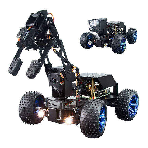
Introduction of PiCar Pro Products 1. About PiCar Pro products PiCar Pro is an open source intelligent robot product for artificial intelligence and robot enthusiasts and students. It is also an open Raspberry Pi-based robot development platform. It has the following features: Easy to assemble: adopting structural modular design, open hardware list and detailed assembly tutorial. - Page 5 Support multiple versions of Raspberry Pi: support Raspberry Pi 3B, Raspberry Pi 3B+ and Raspberry Pi 4. Supporting Python. 2. Two types of PiCar Pro robots PiCar Pro can be assembled into two different forms of robots, namely the robotic arm form and the ultrasonic form. 2.1 Robotic arm shape The PiCar Pro robotic arm has the functions of grabbing objects and visual line tracking, color recognition, moving object detection, Web remote control, OLED...
- Page 6 2.2 Ultrasonic form PiCar Pro has visual line patrol and ultrasonic line patrol, automatic obstacle avoidance, color recognition, moving object detection, Web remote control, OLED display, lighting indicator and other functions; PiCar Pro uses a decelerating DC motor as a power unit, and its advantage is fast; using large-size wheels, PiCar Pro has excellent off-road performance and can be applied to complex terrain;...
-
Page 7: Raspberry Pi
Raspberry Pi 1. Introduction to Raspberry Pi (1) Raspberry Pi Raspberry Pi (Raspberry Pi, RasPi/RPi) is developed by the British charity organization "Raspberry Pi Foundation", based on ARM microcomputer motherboard, only the size of a credit card, but has the basic functions of a personal computer. The original purpose of the Foundation’s development of the Raspberry Pi was to improve the teaching level of the school’s computer science and related disciplines, and cultivate the youth’s computer programming interest and ability. - Page 8 The following contents will briefly explain the main structure ports of the Raspberry Pi 4 motherboard: (1) GPIO 40-PIN pin: The General Purpose Input Output (GPIO) is designed as a slot with two rows of pins on the Raspberry Pi motherboard. GPIO can be used to connect various peripheral electronic devices and sensors to control or monitor these devices through input/output level signals.
- Page 9 (3) Micro HDMI port: High-definition multimedia interface (High Definition Multimedia Interface, HDMI) is a fully digital video and sound transmission interface, used to transmit uncompressed audio and video signals. By connecting it to a display (or TV) equipped with an HDMI interface, the content of the Raspberry Pi can be displayed. The HDMI interface can transmit video and audio signals at the same time, so when we use it, we don't need to connect speakers to the audio interface of the Raspberry Pi.
- Page 10 only needs 700mA, and the 3B+ type requires 2.5A. The chargers of many Android mobile phones can provide the necessary voltage and current for the Raspberry Pi. The current demand of the Raspberry Pi is also related to the connected external device.
- Page 11 (3)Operating system The Raspberry Pi supports a variety of operating systems, mainly based on Liunx and Windows, and most of them can be found on the official website of the Raspberry Pi Foundation (www.raspberrypi.org). The following briefly introduces two representative operating systems. (1) Raspbian Raspbian is the official operating system of the Raspberry Pi Foundation.
- Page 12 (4)Programming language For the Raspberry Pi, there are many programming languages available. In fact, any language that can be compiled for the ARM architecture (such as the C language) can be used for the Raspberry Pi. The most popular language should be Python. In fact, the Pi in the name of the Raspberry Pi was inspired by the word Python.
- Page 13 (2) Introduction of GPIO pins (1) GPIO pin comparison table...
- Page 14 【Form description】: (1) Three naming (coding) methods for Raspberry Pi pins Three ways to name the Raspberry Pi pins: The WiringPi number is the pin number of the functional wiring (such as TXD, PWM0, etc.); the BCM number is the Broadcom pin number, also known as GPIO; the physical number is the number corresponding to the physical location of the pin on the Raspberry Pi motherboard (1 ~40).
- Page 15 3.3V/5V pin and GND pin are commonly known as power and ground pins. The power and ground pins allow your Raspberry Pi to power some external components, such as LED lights. It should be noted that before using these pins to power any external modules or components, care should be taken.
- Page 16 Raspberry Pi through a computer or directly to control the Arduino.
-
Page 17: Introduction Of Robot Hat Driver Board
When you get the PiCar Pro product, you will see a board with its name printed on it called: Adeept Robot HAT, which is an important part of PiCar Pro. There are many interfaces on the Robot HAT driver board. By these interfaces, you can connect some sensors and electronic hardware modules, so that you can achieve many extended functions. - Page 18 can run; if the LED is off, it means that the Robot HAT driver board is not powered 【Tracking】 is the pin interface of Tracking Module. 【WS2812】 is the pin interface of WS2812 Module. 【3.3V-GND】 3.3V power supply interface. 【Uart】 Uart interface. 【GPIO 40-PIN】...
- Page 19 normally. When you use the power adapter to power the Raspberry Pi, you can check the specifications on your power adapter. When the Robot HAT is connected to a load, such as a motor or multiple servos, you need to use a high-current power supply to connect to the Vin on the Robot HAT. You can use two 18650 batteries that support high-current to power the Robot HAT.
- Page 20 and then you can install the servo rocker arm according to the specified angle. After the rocker arm is installed, you can disconnect the servo from the Robot HAT , When you need to install the rocker arm of the second servo, connect the second servo to any servo port on the drive board.
-
Page 21: Lesson 1 Installing And Logging In To The Raspberry Pi System
Lesson 1 Installing and Logging in to the Raspberry Pi System In this lesson, we will learn how to install and remotely log in to the Raspberry Pi system under Windows. And we will download the code program to control the robot. 1.1 Preparation (1) When studying this lesson, you need to prepare the following components first:... - Page 22 Raspbian: https://www.raspberrypi.org/downloads/ After logging in to the official website, click on the location shown below: (2) We need to find out the Raspberry Pi OS (32-bit) with desktop and recommended software. It contains a complete desktop system and recommended software packages.
- Page 23 (3) Choose to download the ".ZIP" file and wait for the download to complete: (4) Find the ".ZIP" file you just downloaded, double-click to open it, and extract it. The uncompressed file format of the file is ".img". Pay attention, you must name...
- Page 24 Only when you encounter a very difficult problem, you can try this method to solve it.Download the Raspbian image file address we provide: https://www.adeept.com/learn/detail-50.html After the download is complete, decompress it. The path of the decompressed .img file must be all English letters and no special characters.
- Page 25 Raspberry Pi. Raspberry Pi Imager is a new image burning tool launched by the Raspberry Pi Foundation. Users can download and run this tool on Windows, macOS and Ubuntu to burn the system image for the Raspberry Pi. Its usage is similar to Etcher and win32diskimager.
- Page 26 (3) Then click "Finish". (4) The software interface after opening is as shown below:...
- Page 27 1.3.2 Burning Raspberry Pi system to SD card with Raspberry Pi Imager (1) Click "CHOOSE OS" on the opened Raspberry Pi Imager software interface.
- Page 28 (2) Click "Use custom" and select a custom ".img" file from your computer, which is the ".img" file of the Raspberry Pi system that we downloaded and decompressed before. (3) Find the ".img" file of the Raspberry Pi system that we downloaded and...
- Page 29 decompressed before. Click "Open". (4) Select the ".img" file and click "Open". (5) Then on the interface of Raspberry Pi Imager, the ".img" file of our selected Raspberry Pi system will appear.
- Page 30 (6) Click "CHOOSE SD". (7) Then select the SD card we need to burn.
- Page 31 (8) Click "WRITE" to write it to the SD card. Wait for the burn to complete. (9) After the burning is completed, the following message will be prompted,indicating that the burning is finished, click "CONTINUE".
- Page 32 【Pay Attention】 Don't remove the SD card after burning! After the Raspberry Pi Imager is burned, the memory card will be ejected in the program. This will cause the subsequent copy operation to prompt that the SD card has not been found. You can unplug the card reader from the computer and then plug it into the computer again.It is necessary to configure SSH and WIFI connection later.
- Page 33 to the Raspberry Pi. After 2016, Raspbian distributions disable the SSH service by default, so we need to manually enable it. (1) We first enter the driver D of the computer, click "View" in the upper left corner, and select "File Extension", as shown below: (2) Right-click on the blank space of the D drive, select "New", and select "Text Document".
- Page 34 above operations. Copy the ssh file to the Raspberry Pi as shown below: 1.5 Setting up Raspberry Pi WIFI wireless connection Next, we also need to set up a WIFI wireless connection for the Raspberry Pi. (1) Create a new file named wpa_supplicant.conf in the root directory of the D driver of the computer.
- Page 35 (4) Write the following contents: country=US ctrl_interface=DIR=/var/run/wpa_supplicant GROUP=netdev update_config=1 network={ ssid="WIFI" psk="PASSWORD" key_mgmt=WPA-PSK priority=1...
- Page 36 WIFI you want to connect; other parts do not need to do any modifications. For example, our company's WIFI name is Adeept, WIFI password is 123456, and the modified wpa_supplicant.conf file is as shown below: (5) Save the set wpa_supplicant.conf file, and then copy it to the root directory of...
- Page 37 (6) Now we can take out the SD card and put it into the "MICRO SD CARD" card slot on the Raspberry Pi development board, and use the Type-C data cable to supply power to the Raspberry Pi. And then the Raspberry Pi will start up and run.
- Page 38 1.6.1.1 Obtaining an IP address with an external display We provide a simple and fast way to get the Raspberry Pi IP address. You need to prepare the following components: (1) One Type-C data cable: used to supply power to the Raspberry Pi. (2) One HDMI cable: used to connect the monitor.
- Page 39 1.Turn on the monitor switch, and connect the mouse to the USB port of the Raspberry Pi, supply power to the Raspberry Pi with the Type-C data cable, then the Raspberry Pi starts. After entering the system interface, we move the mouse cursor to the "...
- Page 40 2. You can also check the following IP address by opening the command window of the Raspberry Pi and entering the following command, you need to write it down: hostname -I 1.6.1.2 Obtaining an IP address with a mobile phone 1.
- Page 41 Click“CONTINUE WITHOUT PERMISSION”:...
- Page 42 Click OK: 3. Wait for the scan to complete. In the list, you find a device named "Raspberry Pi". In the lower left corner, you will see the IP address of the Raspberry Pi: 192.168.3.157. You need to write down this IP address. 1.6.2 Remotely logging in to the Raspberry Pi system This course recommends two kinds of software for SSH login to Raspberry Pi.
- Page 43 1.6.2.1 Putty You need to download and install PuTTY corresponding to your computer system version, and use it to log in to the Raspberry Pi. PuTTY download address: https://www.chiark.greenend.org.uk/~sgtatham/putty/latest.html Run PuTTY, enter the IP address of the Raspberry Pi into the Host Name, and click Open.
- Page 44 password as the Pi itself. The default login name of Raspbian is pi and the password is raspberry. When entering the password, the screen will not display the entered password. After entering raspberry, press Enter to confirm. • You should now have the Raspberry Pi prompt, which will be the same as the prompt on the Raspberry Pi itself.
- Page 45 (2) Download the Portable edition of MobaXterm Home Edition (current version): (3) Find the downloaded file MobaXterm_Portable_v20.2.zip, double-click to open it, unzip it to get a new file. (4) Open the unzipped folder, there is a file MobaXterm_Personal_20.2.exe inside.
- Page 46 (5) Double-click to open MobaXterm_Personal_20.2.exe, and then directly open the MobaXterm software. The interface is as follows: (6) Click "Session" in the upper left corner. (7) Click "SSH".
- Page 47 (8) Enter the IP address of the Raspberry Pi queried before: 192.168.3.157, and click "OK" to confirm. (9) Enter the Raspberry Pi default account: pi, then press the Enter key, and then enter the Raspberry Pi default password: raspberry. Press Enter to log in to the...
- Page 48 Raspberry Pi system. (10) After successfully logging in to the Raspberry Pi system, the following interface will appear: (11) The red box in the figure below is the command window, where you can control the Raspberry Pi by entering commands.
- Page 49 (12) When we close the MobaXterm software and open MobaXterm again to connect to the Raspberry Pi, we can double-click the IP address under "User sessions" on the left: 192.168.3.157, enter the account name: pi, and you can directly connect to the Raspberry Sent.
- Page 50 1.7 Downloading the code program to control the robot After successfully logging in to the Raspberry Pi, we need to download the code program to control the robot. We enter the following command in the console: sudo git clone https://github.com/adeept/adeept_picarpro.git...
- Page 51 After successfully downloading, you will see a new folder adept_picarpro in the file resource list on the left. This folder stores some very important program codes. We will teach you how to use it in detail in the following courses.
- Page 52 1.8 Installing the dependency library of PiCar Pro program We have prepared a script to install all the dependent libraries that need to be used and set up operations such as turning on the camera and automatically running on startup. Steps: 1.
-
Page 53: Lesson 2 How To Use The Web Controller
Lesson 2 How to Use the Web Controller In this lesson, we will learn how to control the Raspberry Pi with the web. The web controller is a web interface used to control the robot products to perform various actions. It can be used on PCs, mobile phones, tablets, and any device that can run a browser. - Page 54 Install the camera cable, contact the metal surface of the cable with the metal surface of the Raspberry Pi (the same applies to installing the camera). Install Robot HAT and camera, and connect the Raspberry Pi power supply. After the Raspberry Pi is turned on (about 30-50s), you can access the Raspberry Pi with a browser.
- Page 55 2.3 What is a web controller The web controller is a web interface used to control the robot products to perform various actions. It can be used on PCs, mobile phones, tablets, and any device that can run a browser. If you install the contents of the software package according to the document, it is very simple to open the web controller.
- Page 56 displayed in your browser to understand their functions and usage. 2.4 Basic module Basic modules can be found in almost all products. These modules are used to control the core functions of robot products. At this time, only the camera can work, and other functions can only be realized after PiCarPro is installed.
- Page 57 CPU Temp: Displaying the Raspberry Pi CPU temperature; CPU Usage: Displaying the CPU occupancy rate of the Raspberry Pi; RAM Usage: Displaying the RAM usage of Raspberry Pi 2.4.3 Move Control Module Controlling the movement of the robot product back and forth. speed: Using the slider to control the speed when the robot moves.
- Page 58 UP: The camera angle of view moves upward DOWN: the camera angle of view moves downward GRAB: clamping chuck LOOSE: Loosening the chuck LEFT: The robotic arm turns to the left RIGHT: The robotic arm turns to the right HANDDOWN: The robotic arm rotates downward HANDUP: The robotic arm rotates upward 2.5 Advanced Function Module Advanced function modules refer to those modules used to perform advanced...
- Page 59 MOTION GET: switching watchdog mode. In this mode, the robot product stops moving and reacts to the moving objects detected in the camera, and the moving objects are framed in the video of the Vedio module. AUTO MATIC: switching automatic obstacle avoidance mode. In this mode, the robot product will automatically advance and use the ultrasonic module to detect obstacles.
- Page 60 COLROR: choosing the color you want to track. START: switching color tracking mode. 2.5.3 CVFL Control Module The switch that controls the visual patrol function. L1, L2: the two parameters L1 and L2 are used to set the height of the two auxiliary lines.
- Page 61 It is used to fine-tune the default angle of the servo, and can correct the angle error generated when the servo is installed. When returning to the center, the rudder will return to this default angle. ①Enter the number of the PWM port connected to the servo you want to fine-tune in the PWM input box.
- Page 62 Controlling the switches of Port1, Port2, Port3 on the development board.
-
Page 63: Lesson 3 How To Control Led
Lesson 3 How to Control LED In this lesson, we will learn how to control LED with Raspberry Pi. 3.1 Components used in this course Components Quantity Picture Raspberry Pi Robot HAT Small LED light 3.2 Introduction of small warm color LED The small warm color LED is a LED that can emit warm white light after being lit. - Page 64 3.3 Wiring diagram (Circuit diagram) When the small warm color LED is used, it needs to be connected to the Port1, Port2, and Port3 on the Robot HAT driver board, as shown in the red box: 3.4 How to control the small warm color LED 3.4.1Run the program of this course 1.
- Page 65 2. Run the command to enter the picarpro/server folder. This folder stores the sample code program for controlling the robot. Enter the following command and press Enter: cd adeept_picarpro/server 3. Enter the command to view the contents of the current directory: 4.
- Page 66 2. Move the cursor by using the up, down, left, and right keys. After editing the code, press "Ctrl + X" --> "Y" --> "Enter" to save the code. If you have not edited the code, just press "Ctrl + X" to exit. Option two: 1.
- Page 68 3. When you need to save the modified file, you can press the shortcut key "Ctrl+S", then select "Yes". If there is a "Permission denied" error, just run the command in MobaXterm: sudo chmod -R 777 adeept_picarpro/server 3.4.3 Main code program Complete code reference file switch.py 1.
- Page 69 import time 2. The switchSetup function sets the GPIO pin numbers of the Raspberry Pi corresponding to the interface to 5, 6, and 13, here we use BCM coding. switchSetup(): GPIO.setwarnings(False) GPIO.setmode(GPIO.BCM) GPIO.setup(5, GPIO.OUT) GPIO.setup(6, GPIO.OUT) GPIO.setup(13, GPIO.OUT) 3. The switch function sets the high and low levels of the interface. Port represents ports 1-3.
- Page 70 set_all_switch_off(): switch(1,0) switch(2,0) switch(3,0) 5. Instantiating the object and executing the method function means always while 1 looping, means calling the above function. This code switchSetup、switch、set_all_switch_off keeps the light on for 1 second and then be off for 1 second. __name__ == "__main__": switchSetup() while...
-
Page 71: Lesson 4 How To Control 180° Servo
Lesson 4 How to Control 180° Servo In this lesson, we will learn how to control 180° Servo. 4.1 Components used in this course Components Quantity Picture Raspberry Pi Robot HAT 180°Servo 4.2 Introduction of 180° Servo What is a servo? The servo is a position (angle) servo driver, which is suitable for those control systems that require constant angle changes and can be maintained. - Page 72 4.3 Wiring diagram (Circuit diagram) When the 180°Servo module is in use, it needs to be connected to the servo interface on the RobotHAT driver board. The yellow wire is connected to the yellow pin, the red wire is connected to the red pin, and the brown wire is connected to black pin,as shown below: 4.4 How to control 180°Servo...
- Page 73 4.4.1Run the code 1. Remotely log in to the Raspberry Pi terminal. 2. Enter the command and press Enter to enter the folder where the program is located: cd adeept_picarpro/server/ 3. View the contents of the current directory file: 4. Enter the command and press Enter to run the program: sudo python3 servo.py 5.
- Page 74 After the above hands-on practice, you already know how to use and run our course sample code program. Then you must be curious to know how our code program is programmed on the Raspberry Pi to control the 180° servo. Let's learn about the main code program together.
- Page 75 Using the above code can make the servo rotate slowly back and forth between 300 and 400, but this method of controlling the servo also has great drawbacks. When the program is executed to the slow motion part of the servo, it will be blocked, which will seriously affect the program.
-
Page 76: Lesson 5 How To Control Ws2812 Led
Lesson 5 How to Control WS2812 LED In this lesson, we will learn how to control WS2812 LED. 5.1 Components used in this course Components Quantity Picture Raspberry Pi Robot HAT 3 pin wire WS2812 RGB LED 5.2 Introduction of WS2812 RGB LED WS2812 RGB module is a low-power RGB tri-color lamp with integrated current control chip. - Page 77 WS2812 LED is a very commonly used module on our robot products. There are three WS2812 LEDS on each module. Pay attention to the direction of the signal line when connecting. The signal line needs to be connected to the “IN” port of WS2812 LED after being led from the Raspberry Pi.
- Page 78 5.4 How to control WS2812 LED 5.4.1Run the code 1. Remotely log in to the Raspberry Pi terminal. 2. Enter the command and press Enter to enter the folder where the program is located: cd adeept_picarpro/server/ 3. View the contents of the current directory file:...
- Page 79 4. Enter the command and press Enter to run the program: sudo python3 LED.py 5. After running the program successfully, you will observe that the WS2812 light turns red. 5.4.2 The main code program of this lesson For the complete code, please refer to the file LED.py. import time from rpi_ws281x import * The third-party library rpi_ws281x can be used to control the ws_2812 module...
-
Page 80: Lesson 6 Displaying Text On The Oled Screen
self.LED_BRIGHTNESS, self.LED_CHANNEL self.strip.begin() colorWipe(self,color): # This function is used to change the color of the LED lamp range(self.strip.numPixels()): #Only one LED lamp color can be set at a time, so a cycle is required self.strip.setPixelColor(i, color) self.strip.show() #After calling the show method, the color will really change Build LED control class. - Page 81 6.2 Introduction of OLED Screen OLED (Organic Light-Emitting Diode), also known as organic electric laser display, organic light emitting semiconductor (Organic Electroluminesence Display, OLED). OLED is a kind of current-type organic light-emitting device, which produces light by the injection and recombination of carriers, and the luminous intensity is proportional to the injected current.
- Page 82 6.3 Wiring diagram (Circuit diagram) If you want to use the OLED Screen module, you need to connect the IIC interface on the Robot HAT driver board, as shown in the figure below: 6.4 How to display text on the OLED screen 6.4.1Run the code 1.
- Page 83 located: cd adeept_picarpro/server/ 3. View the contents of the current directory file: 4. Enter the command and press Enter to run the program: sudo python3 OLED.py 5. After running the program successfully, you will observe that the word "GEWBOT.COM" will be displayed on the OLED screen. 6.
- Page 84 Import dependent libraries and initialize. run(): with canvas(device) as draw: draw.text((0, 0), text_1, fill="white") draw.text((0, 10), text_2, fill="white") draw.text((0, 20), text_3, fill="white") draw.text((0, 30), text_4, fill="white") draw.text((0, 40), text_5, fill="white") draw.text((0, 50), text_6, fill="white") __name__ == '__main__': run() Light up the OLED screen.
-
Page 85: Lesson 7 How To Control Dc Motor
Lesson 7 How to Control DC Motor In this lesson, we will learn how to control DC Motor. 7.1 Components used in this course Components Quantity Picture Raspberry Pi Robot HAT DC Motor 7.2 The introduction of DC Motor PiCarPro robot products use DC motor as a power device. DC motor is a device that converts DC electrical energy into mechanical energy. - Page 86 7.4 How to control Motor 7.4.1Run the code 1. Remotely log in to the Raspberry Pi terminal. 2. Enter the command and press Enter to enter the folder where the program is located: cd adeept_picarpro/server/ 3. View the contents of the current directory file:...
- Page 87 4. Enter the command and press Enter to run the program: sudo python3 move.py 5. After running the program successfully, you will observe that the Motor will rotate for about 1 second and then stop, and the program will also stop. If you need the motor to rotate again, you need to run the program again.
- Page 88 Set the motor initialization function. destroy(): motorStop() GPIO.cleanup() # Release resource Set the motor stop function. move(speed, direction, turn, radius=0.6): # 0 < radius <= 1 #speed = 100 direction == 'forward': turn == 'right': motor_left(0, left_backward, int(speed*radius)) motor_right(1, right_forward, speed) elif turn == 'left': motor_left(1, left_forward, speed)
-
Page 89: Lesson 8 How To Control The Ultrasonic Module
Lesson 8 How to Control the Ultrasonic Module In this lesson, we will learn how to read the data of the RGB ultrasonic ranging module. 8.1Components used in this course Components Quantity Picture Raspberry Pi Robot HAT ultrasonic module 4 pin wire 8.2 Introduction of RGB ultrasonic ranging module The ultrasonic ranging module used in our PiCarPro product has four pins, namely VCC, GND, Echo and Trig. - Page 90 duration of the high level is the time from emission to return of the ultrasonic wave. The principle of distance detection by ultrasonic ranging sensor: the method of detecting distance by ultrasonic is called echo detection method, that is, the ultrasonic transmitter emits ultrasonic waves in a certain direction, and the timer starts timing at the same time as the launch time.
- Page 91 8.3Wiring diagram (Circuit diagram) When using Robot HAT driver board, you need to connect the ultrasonic sensor to the Ultrasonic interface on the driver board. Do not connect it to the IIC port to avoid burning the ultrasonic module. (IIC is an interface used to connect I2C devices, and the pin positions of VCC and GND are different from Ultrasonic).
- Page 92 8.4.1Run the code 1. Remotely log in to the Raspberry Pi terminal. 2. Enter the command and press Enter to enter the folder where the program is located: cd adeept_picarpro/server/ 3. View the contents of the current directory file: 4. Enter the command and press Enter to run the program: sudo python3 ultra.py 5.
- Page 93 For the complete code, please refer to the file ultra.py. import RPi.GPIO as GPIO import time Tr = 11 # The pin number of the input end of the ultrasonic module Ec = 8 # Pin number of the output end of the ultrasonic module GPIO.setmode(GPIO.BCM) GPIO.setup(Tr, GPIO.OUT,initial=GPIO.LOW) GPIO.setup(Ec, GPIO.IN)
-
Page 94: Lesson 9 How To Assemble Picar Pro
Lesson 9 How to Assemble PiCar Pro 9.1Components used in this course The components we provide: RobotHAT driver board x 1 LED headlight x 1 18650 battery holder LED strip x 1 MPU6050(pin header)x 1 Camera... - Page 95 180 degree AD002 servo x 3 3pin cable(for ws2812) x 1 4pin cable x 2 40CM camera cable(black) x1 Small LED light x2 DC gear motor JGA25-370 DC12V130RPM(with 2pin cable) x2 Internal 4mm coupling (with screws) X2...
- Page 96 Big wheels x4 180 degree MG946R servo x4 Inner 4mm long 22mm plastic tube x2 Red metal rocker x1 OLED screen(anti-reverse connection interface) x1...
- Page 97 ultrasonic module Servo extension cable x2 Tracking module 5pin cable x1 Copper pillar Round head screw (black) M2*8 M2.5*14 M2*14 M3*60 M2.5*4 x6(silver) M2.5*8 M2.5*12 Gasket M3*4 M3*16 M4*8*1 M3*10 M4*6 x1(silver) M4*25 x1(silver) M4*40 x4(silver)...
- Page 98 Double pass nylon column Flat head screw M3*15 M3*6 M3*20 M3*40 self-tapping screw Hex nuts M1.4*6 x23(black) M1.7*6*6 x13(black) x1(silver) Locknut Mechanical parts bearings MF84ZZ A set of aluminum alloy...
- Page 99 A set of acrylic...
- Page 100 Small Cross-head Screwdriver Cross Socket Wrench Large Cross-head Screwdriver Large straight Screwdriver 20CM Winding Pipe...
- Page 101 Bring your own components: Raspberry Pi x1 18650 battery (high current power battery) x2 9.2 Precautions for assembly Due to the large number of servo used in this product, the installation of the servo has a greater impact on the performance of the product, so you need to power on the servo and control the servo to rotate to the middle position before installing the servo rocker arm, in this way, the rocker arm of the servo installed at the specified angle can be in the middle position of it.
- Page 102 3.After the Raspberry Pi is powered on, it will automatically run webServer.py, and after webServer.py is running, it will control all the servo ports to send signals to move to the middle position. When you install the servo rocker arm, you can connect the servo to any port at any time.
- Page 103 Raspberry Pi is installed with RobotHAT, you can connect the USB cable to the USB port on the RobotHAT. RobotHAT will power the Raspberry Pi with the GPIO interface. 2. Different raspberry parties have different current requirements. For example, the Raspberry Pi 3B needs at least 2A to boot up, and the Raspberry Pi 4 needs 3A to boot normally.
- Page 104 supports power supply below 15V. 9. When installing the servo rocker arm in the structure assembly, you can use the USB cable to power the RobotHAT. After the Raspberry Pi with the robot software installed, it will control the RobotHAT to set all the servo ports to output neutral signals.
- Page 105 •In order to make the structural assembly process more intuitive, we dye the screws used in the product. During the assembly process, you can refer to the fastener color in the tutorial to determine which type of screw and nut to use. •The actual color of the product is subject to the product, and the actual screws are not colored.
- Page 106 9.4.2 Robotic arm assembly note: 1. When installing the servo, the gear of the servo should be in the middle of the servo rotation range. 1. 2. After installing the software in the Raspberry Pi, the Raspberry Pi will automatically run the robot product program when the Raspberry Pi is turned on. After powering on the servo, the drive board will automatically place the servo in the middle position.
- Page 107 Prepare the acrylic panel shown on the right side of the above picture. There is no need to fix it on the assembled component. Since the acrylic panel on the right has directions, the rendering diagram will fix it on the component to indicate the subsequent assembly position.
- Page 108 Prepare the acrylic panel and acrylic gasket as shown in the picture above.
- Page 109 Use M3X16 screws and M3-LOCK lock nuts to fix the acrylic panel and acrylic washer as shown in the figure on the side panel. It should be noted that the lock nut should not be tightened too tightly, because this is the rotating pair of the movable part.
- Page 110 Use M2X8 screws and M2 nuts to fix the AD002 servo on the acrylic panel shown in the figure above. The acrylic panel here is similar in shape to the acrylic panel just installed, except that there are more mounting holes for fixing the servo.
- Page 111 It looks like the picture above after installation. Prepare the acrylic panel (top panel of GRIPPER) and AD002 servo as shown in the picture. Use M2X8 screws and M2 nuts to fix AD002 servo to the upper panel of the arm chuck.
- Page 113 Assemble the upper panel and lower panel of the chuck. Here you can load the gear shown above between the servo arm and the lower panel. For the time being, you don’t need to fix it. You only need to know that the gear is installed here. The gear is clamped in this position to avoid the gear cannot be installed due to too small gap after assembly.
- Page 114 Use M2.5*12 screws and M1.7*6*6 self-tapping screws to fix...
- Page 115 Use four M3X20 nylon posts and eight M3X10 screws to fix the left and right panels of the chuck together.
- Page 119 Use three M3X10 screws to fix the acrylic washer and M3X40 nylon column to the side panel of the robot arm.
- Page 120 Use three M3X10 screws to fix the panel on the other side. Use M1.7X6X6 self-tapping screws to fix the side panel and the servo arm, and use M2.5X8 screws to fix the servo to the side panel.
- Page 122 The assembled look is shown in the figure above. Prepare the gear on the other side and the connecting rod parts for the chuck.
- Page 124 The installation method is shown in the figure above. Use M3X10 screws and M3-LOCK locknuts to assemble the connecting rods.
- Page 125 The robot arm after assembly is as shown in the figure above. 9.4.3 PTZ installation note: 1. When installing the servo, the gear of the servo should be in the middle of the servo rotation range. 2. After installing the software in the Raspberry Pi, the Raspberry Pi will automatically run the robot product program when the Raspberry Pi is turned on.
- Page 126 Prepare 2 large servos (MG946R), a camera, and the following parts. Use 8 M2 nuts on the front and back sides of the camera mounting hole, use M2*8 screws to pass through the aluminum alloy and the camera and fix them with M2 nuts.
- Page 127 Use M3*4 screws to fix two "L"-shaped aluminum alloys.
- Page 128 Use M3*4 screws to pass through the aluminum alloy and "L" aluminum alloy to fix the servo.
- Page 129 Install an M3*10 screw, no need to fix, for the connection of the PTZ and the robot arm. Use M3*10 screws to pass through the aluminum alloy and the servo and fix them with M3 nuts. Install the steering wheel.
- Page 131 9.4.4 Body installation note: 1. When installing the rocker arm of the servo, the gear of it should be in the middle of the rotation range of the servo, and then install the servo as shown in the figure below. 2.
- Page 132 Install the aluminum alloy and fix it with M3 lock nuts (all lock nuts in this course do not need to be tightened). Prepare the aluminum alloy as shown below.
- Page 133 Install the aluminum alloy pictured above. Use 4 M3*4 screws to pass through the aluminum alloy and the "L" aluminum alloy on the servo to fix the servo. Install the PTZ. Use M3*4 screws to pass through the aluminum alloy and fix with M3*15 nylon posts.
- Page 134 Prepare the aluminum alloy sheet (as shown by the arrow in the figure below), M4*40 screws, F624ZZ bearing (large), aluminum alloy, M4*8*1 gasket, plastic tube, and M4 nut. Use M4*40 screws to pass through the aluminum alloy sheet, F624ZZ bearing, aluminum alloy, gasket, plastic tube, and M4 nut from the inside to the outside.
- Page 135 shown below. Use M3*10 screws to fix aluminum alloy and aluminum alloy sheet.
- Page 136 Install the tire and fix it with M4 locknut.
- Page 137 Install small LED lights.
- Page 138 Repeat the above steps to assemble the structure on the other side. Use M4*40 screws to pass through these from top to bottom: MF84ZZ bearing (small), aluminum alloy (long large hole), aluminum alloy (small hole), aluminum alloy (small hole), aluminum alloy (long large hole) , MF84ZZ bearing (small), M4 nut.
- Page 140 Use M4*40 screws to pass through these from top to bottom: F624ZZ bearing (large), MF84ZZ bearing (small), aluminum alloy (large hole), aluminum alloy (small hole), aluminum alloy (small hole), aluminum alloy (large hole), F624ZZ bearing (large), M4 nut. As shown below.
- Page 143 Install WS2812 LED lights. Use M2*14 screws to pass through the aluminum alloy, M2*6 copper column, ws2812 LED lights and fix them with M2 nuts.
- Page 144 Install the battery holder. Use M3*6 countersunk screws to pass through the battery holder, aluminum alloy and fix them with M3 nuts. Install the Raspberry Pi and Robot HAT driver board. Use M2.5*4 screws to penetrate the bottom of the aluminum alloy and fix them with M2.5*4+6 copper pillars. Fix the Raspberry Pi with M2.5*4+6, install the camera cable, use M2.5*14 copper pillars to place between the Raspberry Pi and the Robot HAT board,use M2.5*4 screws to fix the robot HAT board.
- Page 146 Install the rear wheel. Install the motor on the bottom of the aluminum alloy, and use M3*4 screws to pass through the aluminum alloy to fix the motor.
- Page 147 Install the inner 4mm coupling and fix it with screws.
- Page 148 Install the rear wheel. Use M2.5*4 countersunk screws to fix. Install the OLED screen. Use M2*8 screws to pass through the aluminum alloy and OLED and fix them with M2 nuts.
- Page 149 Use M3*4 screws to fix the M3*60 copper column with aluminum alloy, and use M3*4 screws to fix the aluminum alloy.
- Page 150 9.4.5 Installing the robotic arm Use M3*10 screws to fix the position of the robot arm, and use two M1.7*6*6 self-tapping screws to fix the direction of the robot arm. Use M3 lock nut to fix the other end. The installation is complete.
- Page 151 9.4.6 Install Ultrasonic Mode When using the ultrasonic mode, the camera installation method is the same as the PTZ installation method. Because the shovel is equipped with a camera, when the ultrasonic mode is selected, the camera on the PTZ must be removed and installed in the designated position.
- Page 152 Install ultrasonic mode. It is the same as the method of installing the robot arm. Use M3*10 screws to fix the position of the robot arm, and use two M1.7*6*6 self-tapping screws to fix the direction of the robot arm. Use M3 lock nut to fix the other end.
- Page 154 The installation is complete. 9.5 Circuit Wiring Diagram Robot HAT board interface diagram...
- Page 155 Wiring method 1. If you don't know how to connect the camera, you can refer to the official documentation of the Raspberry Pi camera. 2. The motor on the left is connected to the MOTOR-B port; the motor on the right is connected to the MOTOR-A port.
- Page 156 Port 3 servo port. 7. The servo that controls the clamping action of the chuck is connected to the Port 4 servo port. 8. The ultrasonic module is connected to the Ultrasonic port with a 4pin wire. Never connect the ultrasonic to the IIC port, which will cause permanent damage to the ultrasonic module.
-
Page 157: Lesson 10 Tracking Function
Lesson 10 Tracking Function In this lesson, we will learn how to use tracking function of PiCarPro. 10.1 Tracking Module Classic Car and Racing Car are driving on the white paper "road" with black lines. Because the black line and white paper have different reflection coefficients of light, the "road"... - Page 158 obstacles, please disassemble the tracking module to avoid damage to the tracking module. 2. Making a patrol track. Due to the limitation of the steering range of the front wheel servo, the curve radius of the track cannot be too small.
- Page 159 10.3 Turn on the tracking function 10.3.1 Running tracking program 1. Turn on PiCarPro, the boot time is about 1 minute. 2. After PiCarPro is turned on, enter the IP address of your Raspberry Pi with the Google browser of your mobile phone or computer, and access port 5000, for example: 192.168.3.44:5000 (see lesson 2 for detailed steps).
- Page 160 6. The height of PiCar Pro's tracking module from the ground is about 7mm. When the Tracking module cannot be used normally, please refer to: Tracking module adjustment tutorial. Tutorial link: https://www.adeept.com/learn/detail-50.html 10.3.2 Main code program For the complete code, please refer to the file findline.py.
- Page 161 setup(): GPIO.setwarnings(False) GPIO.setmode(GPIO.BCM) GPIO.setup(line_pin_right,GPIO.IN) GPIO.setup(line_pin_middle,GPIO.IN) GPIO.setup(line_pin_left,GPIO.IN) Define the main function of the hunt module. run(): status_right = GPIO.input(line_pin_right) status_middle = GPIO.input(line_pin_middle) status_left = GPIO.input(line_pin_left) # Detect whether the line hunting module senses lines. status_middle == 1: print('forward') elif status_left == 1: print('left') elif status_right == 1:...
-
Page 162: Lesson 11 Warning Light Function
Lesson 11 Warning Light Function In this lesson, we will learn how to use PiCarPro's warning light function. 11.1 Function introduction This section of the course introduces the use of multi-threading to achieve some effects related to WS2812 LED lights. Multi-threading is a very common operation we use in robot projects, because robots have high requirements for real-time response. - Page 163 11.2.1 Running the warning light program 1. Turn on PiCarPro, the boot time is about 1 minute. 2. After PiCarPro is turned on, enter the IP address of your Raspberry Pi with the Google browser of your mobile phone or computer, and access port 5000, for example: 192.168.3.44:5000 (see lesson 2 for detailed steps).
- Page 164 time.sleep(0.1) range(0,3): self.colorWipe(Color(255,0,0)) time.sleep(0.05) self.colorWipe(Color(0,0,0)) time.sleep(0.05) time.sleep(0.1)
-
Page 165: Lesson 12 Ultrasonic Scanning Function
Lesson 12 Ultrasonic Scanning Function In this lesson, we will learn how to use PiCarPro's ultrasound scanning function. 12.1 Function introduction Ultrasonic scanning function means that after running the program, PiCarPro will rotate to detect the surrounding environment with the ultrasonic module. When there are obstacles around, it will display a red dot on the screen. - Page 166 3. Place the car at the location to be detected. 4. Click the "SCAN" pattern, PiCarPro will start to rotate and detect the surrounding environment. After the detection is completed, there will be red dots in the pattern where there are obstacles. 12.4.2 Main code program For the complete code, please refer to the file functions.py.
- Page 167 #Servo pin. Set as the pin of the servo on your product that can control the left and right rotation of the ultrasonic module. servoPin = 1 GPIO.setmode(GPIO.BCM) GPIO.setup(UPin1, GPIO.OUT,initial=GPIO.LOW) GPIO.setup(Upin2, GPIO.IN) pwm = Adafruit_PCA9685.PCA9685() pwm.set_pwm_freq(50) pwm0_init = 300 pwm0_max = 450 # Set the maximum scanning angle pwm0_min...
- Page 168 Execution function __name__ == '__main__': radar_scan() GPIO.cleanup()
-
Page 169: Lesson 13 Camera Stabilization Function
Lesson 13 Camera Stabilization Function In this lesson, we will learn how to use PiCarPro's camera stabilization function and its application scenarios. 13.1 Camera application scenarios When the car is driving on a non-level ground, in order for the camera to take a horizontal picture, the camera stabilization function is required. - Page 170 3. Place the car on the prepared patrol track. 4. Click "STEADY CAMERA", PiCarPro has the camera stabilization function. 5. When you want to terminate the camera stabilization function, you can click "STEADY CAMERA" again. 13.2.2 Main code program For the complete code, please refer to the file steady.py. Import dependencies and initialize.
-
Page 171: Lesson 14 Automatic Obstacle Avoidance Function
Lesson 14 Automatic Obstacle Avoidance Function In this lesson, we will learn how to use PiCarPro to achieve automatic obstacle avoidance. 14.1 Introduction to Automatic Obstacle Avoidance Since the camera used by our Raspberry Pi robot is a monocular camera and cannot collect depth information, many of our robot products use ultrasonic ranging modules to obtain depth information and detect whether there are obstacles in a certain direction to get the distance of the obstacle. - Page 172 14.2 Turning on Automatic Obstacle Avoidance function 14.2.1 Running the Automatic Obstacle Avoidance program 1. Turn on PiCarPro, the boot time is about 1 minute. 2. After PiCarPro is turned on, enter the IP address of your Raspberry Pi with the Google browser of your mobile phone or computer, and access port 5000, for example: 192.168.3.44:5000 (see lesson 2 for detailed steps).
- Page 173 3. Place the car on the prepared patrol track. 4. After clicking "AUTO MATIC", the robot will automatically avoid obstacles when encountering obstacles. . 5. When you want to terminate the Automatic Obstacle Avoidance function, you can click "AUTO MATIC" again. 14.2.2 The main code program of this lesson For the complete code, please refer to the file functions.py.
- Page 174 servoLeft = 180 #Left position of the servo servoRight = 480 #The right position of the servo rangeKeep = 0.3 #Avoidance distance scanDir = 1 #Scan direction, 1 is from left to right, -1 is from right to left scanPos = 1 #Store the current scan position (1 is the left, 2 is the middle, and 3 is the right) scanNum = 3 #The number of scan positions (left, middle, and right, these are three positions)
- Page 175 min(scanList) < rangeKeep: scanList.index(min(scanList)) == 0: #The shortest distance detected on the left Turn right print('Turn right') elif scanList.index(min(scanList)) == 1: #The shortest distance detected in the middle scanList[0] < scanList[2]: If the detected distance on the left is shorter than the right, turn to the right print('Turn right') else:...
-
Page 176: Lesson 15 Creating A Wifi Hotspot On Raspberry Pi
You can use your phone or computer to search for the WIF named Adeept. The default password is 12345678. Once the connection is successful, you can log in to 192.168 .12.1: 5000... - Page 177 Adeept is the name of the WIFI hotspot, 12345678 is the password of the WIFI hotspot.
Need help?
Do you have a question about the PiCar-Pro and is the answer not in the manual?
Questions and answers