Table of Contents
Advertisement
Quick Links
Advertisement
Table of Contents

Related Manuals for Safety Vision RoadRecorder 9000


Summary of Contents for Safety Vision RoadRecorder 9000
- Page 1 ROADRECORDER 9000 ® USER GUIDE Linux OS...
- Page 2 However, because of Safety Vision’s policy of continual product improvement, Safety Vision reserves the right to amend the information in this document at any time without prior notice. This material is confidential and the property of Safety Vision.
-
Page 3: Table Of Contents
ROADRECORDER® 9000 USER GUIDE CONTENTS PART 1: HARDWARE Components Front Panel Rear Panel Hard Drive Canister LCD Control Panel Wiring Diagram Flat Mount Installation Removing / Inserting the Hard Drive LCD Control Panel Operation PART 2: CONFIGURATION Connecting to the NVR Help Windows Product Details Admin... - Page 4 ROADRECORDER® 9000 USER GUIDE Recorder Status WiFi Status Acceleration Status Tag Events Video Live View Snapshot Viewer Video Out Appendix A: Specifications Appendix B: Dimensions FCC Compliance Statement...
-
Page 5: Part 1: Hardware
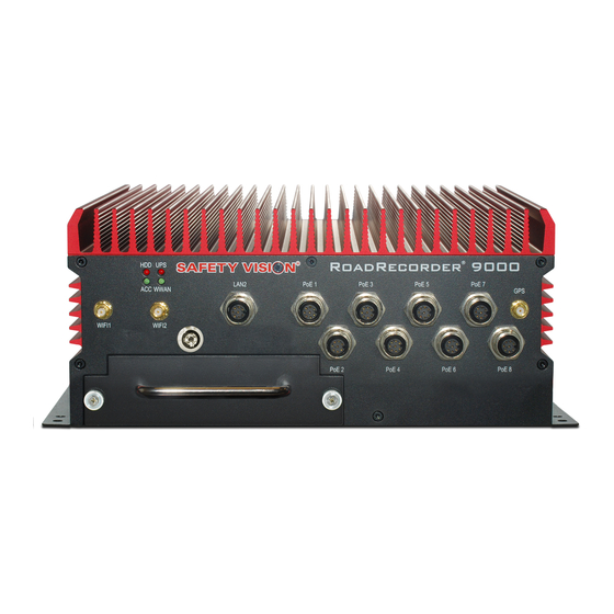
ROADRECORDER® 9000 USER GUIDE PART 1: HARDWARE Components Front Panel System Status LEDs: PoE 1 – PoE 8: • • 8-pin A-Code M12 Gigabit Power over Ethernet (PoE) NIC. ◦ BLINKS – When there is Reading and Writing Activity. • Type 2 Class 4 PoE (25.5-Watt 53VDC). -
Page 6: Rear Panel
ROADRECORDER® 9000 USER GUIDE Rear Panel Cellular Components: Grounding Stud: • SIM CARD – Cellular modem supported (not included). • Used for grounding NVR case to chassis. • ANT1 – Cellular Main antenna input. GPIO / COM3: HDMI Port: • Sub DB 15 Male Connection ◦... -
Page 7: Hard Drive Canister
ROADRECORDER® 9000 USER GUIDE Hard Drive Canister Status LEDs: • ◦ BLINKS – When there is Reading and Writing Activity. • ◦ SOLID – Power is being supplied. USB Port: • USB 3.0 port for connection to a PC. Data Port 1 / Data Port 2: •... -
Page 8: Lcd Control Panel
ROADRECORDER® 9000 USER GUIDE LCD Control Panel LCD Display Displays the NVR’s name, date/time, alerts, and statuses. ESC Button Press the ESC button to cancel the current command and return to the display. Navigation Keys Use the left, right, up, and down keys to navigate menus or move the cursor. Press the center key to display the Main Menu/ enter a command. -
Page 9: Wiring Diagram
ROADRECORDER® 9000 USER GUIDE Wiring Diagram... -
Page 10: Flat Mount Installation
ROADRECORDER® 9000 USER GUIDE Flat Mount Installation Secure the RoadRecorder 9000 NVR to the mounting surface using the appropriate fasteners. Ensure that the front panel of the NVR remains accessible, and that there is a minimum 2.5 inches of clearance for cables. -
Page 11: Removing / Inserting The Hard Drive
ROADRECORDER® 9000 USER GUIDE Removing / Inserting the Hard Drive To remove the hard drive from the NVR Ensure the NVR is powered OFF. 2. Insert the key into the hard drive lock and turn it counterclockwise. 3. Turn the two hard drive thumb screws counterclockwise until they are loose. 4. -
Page 12: Lcd Control Panel Operation
ROADRECORDER® 9000 USER GUIDE LCD Control Panel Operation Main Menu Manual Offload Press the center navigation key to display the Main Menu. Select the Manual Offload option to manually offload recorded There are four options available: System Details, System Logs, video to a USB flash drive inserted into the NVR. -
Page 13: Part 2: Configuration
ROADRECORDER® 9000 USER GUIDE PART 2: CONFIGURATION The RoadRecorder 9000 NVR can be configured through the on-board web interface, which must be accessed with a PC and web browser. Connecting to the NVR Use the following procedure to access the web-based configuration menus using the default IP address: Connect the PC to the NVR’s Ethernet LAN 1 RJ-45 port with a standard Ethernet cable. -
Page 14: Help Windows
ROADRECORDER® 9000 USER GUIDE Help Windows Each screen of the RoadRecorder 9000 NVR configuration web interface includes a comprehensive help menu. The help menus explain the functionality and parameters of each field. To access the help menu for a screen, simply click the Help button at the top right of the screen. -
Page 15: Admin
To update the NVR’s firmware, click the Download NVR Select Save File in the web browser prompt, then click OK. Firmware from Safety Vision link to be directed to Safety The configuration file is automatically saved in the PC’s Vision’s FTP site. - Page 16 ROADRECORDER® 9000 USER GUIDE (Firmware / Config cont.) Navigate to and select the correct NVR firmware package to download. The web browser prompt appears. Select Save File in the web browser prompt, then click OK. The firmware file is automatically saved in the PC’s Downloads folder. Click the Browse…...
-
Page 17: Storage
ROADRECORDER® 9000 USER GUIDE Storage Select the Admin tab from the top, then click Storage. The Storage page allows you to configure the storage device(s) of the NVR. Primary Storage • Secondary Storage Media: This field is auto populated • Delete file option for secondary storage: Select the •... -
Page 18: Network Settings
ROADRECORDER® 9000 USER GUIDE Network Settings Select the Admin tab from the top, then click Network. The Network Settings page configures the network interfaces and features. MNVR Detail • Server IP address: Enter the Mail Server IP address, which will be used to send e-mails when an event is triggered •... - Page 19 ROADRECORDER® 9000 USER GUIDE (Network Settings cont.) Wifi Interface Select this option to enable the NVR’s internal WLAN. Click on View Wifi Configuration to launch the Wifi Configuration window. (See Wifi Configuration section below) Wifi Configuration The Wifi configuration window configures which Access Points the NVR will connect to. Available Wireless Profiles: Click the Scan button, then click OK to perform a site survey of all Access Points available.
- Page 20 ROADRECORDER® 9000 USER GUIDE (Network Settings cont.) POE 8 Network Interface • Server IP address: Enter the IP address for the server hosting the SafetyNet software. Select this option to enable PoE 8 as a separate network interface • Server Port: Default server port. •...
-
Page 21: Date / Time
ROADRECORDER® 9000 USER GUIDE Date / Time Select the Admin tab from the top, then click Date / Time. The Date / Time page configures the NVR’s time zone. Timezone: Select the appropriate time zone from the dropdown menu. Time Sync Priority Use the Time Sync Priority fields to select which device has priority in providing the NVR with Date/Time data. -
Page 22: Users / Passwords
ROADRECORDER® 9000 USER GUIDE Users / Passwords Select the Admin tab from the top, then click Users / Passwords. The Users / Passwords page allows users to change passwords for logging in to the webUI and the password required to access the NVR’s LCD Control Panel. -
Page 23: Settings
ROADRECORDER® 9000 USER GUIDE Settings Startup & Shutdown Select the Settings tab from the top, then click Startup/Shutdown. The Startup/Shutdown page allows you to configure startup and shutdown conditions of the NVR. Startup for the specified duration after the vehicle’s ignition has been turned off. - Page 24 ROADRECORDER® 9000 USER GUIDE (Startup & Shutdown cont.) Internal UPS • Backup Power Record Duration: Enter the amount of time, between 0 to 10 minutes (decimal values are not allowed), the NVR will continue to record when a battery power failure has occurred, and internal UPS is supplying backup power. Scheduled Reboot •...
-
Page 25: Audio / Video
• Add Credential: If using a newly released IP camera or a Non-Safety Vision IP camera that is ONVIF Profile S compliant, users must add the credentials in order for the NVR to discover the camera. Click the Add Credential button, and enter the username and password, then click the Add to List button. - Page 26 ROADRECORDER® 9000 USER GUIDE Discovery Result NOTE: Discovered cameras will be listed in the order they were discovered, NOT in the order they are connected to the NVR. If using the Discovery Result page to configure cameras, users MUST arrange cameras in the order they are connected to the NVR by clicking in the ‘No.’...
- Page 27 ROADRECORDER® 9000 USER GUIDE (Audio / Video cont.) Total Audio + Video Device(s): Click in the field and select the • Rotation: Click in the field to rotate the camera image number of cameras connected to the NVR. (if needed). •...
-
Page 28: Poe Settings
ROADRECORDER® 9000 USER GUIDE PoE Settings Select the Settings tab from the top, then click PoE Settings. The PoE Settings page allows users to turn on/off the NVR’s PoE ports. If the PoE box is checked, PoE port is active and receiving power. By default, all PoE boxes are checked. To turn off power to a PoE port, uncheck the PoE box. -
Page 29: Sensor Settings
ROADRECORDER® 9000 USER GUIDE Sensor Settings Select the Settings tab from the top, then click Sensor Settings. The Sensor Settings page configures the NVR’s sensor inputs and their trigger settings, the relay outputs, and fault statuses. Sensor Inputs: Select the number of sensor inputs, between will also be found in Metadata Log. - Page 30 ROADRECORDER® 9000 USER GUIDE (Sensor Settings cont.) Select the following items to display specific camera views on • Selecting None will disable a control output. an external monitor when a sensor input is triggered: • Selecting an individual fault status from the dropdown •...
-
Page 31: Recording
Restrictions: File size can be configured from 50 MB to 1024 MB. Decimal values not allowed. Click Save Changes to save changed entries. NOTE: Safety Vision strongly recommends retaining the default settings of 100 MB. Event Recorder Settings •... -
Page 32: Thresholds
ROADRECORDER® 9000 USER GUIDE Thresholds Select the Settings tab from the top, then click Thresholds. The Thresholds page configures the threshold values of specific equipment before events are recorded. Ignition • Startup minimum ignition value: Select the minimum ignition value (in volts) to start NVR system. NVR system will power on only if ignition power is greater than the configured ignition value. -
Page 33: Gps / Geo Fence
ROADRECORDER® 9000 USER GUIDE GPS / GEO Fence Select the Settings tab from the top, then click GPS / GEO Fence. The GPS / GEO Fence page configures the GPS signal priority and sets up the Geo Fence feature. GPS Priority up to 5 polygons on the map (See Circle and Polygon below). - Page 34 ROADRECORDER® 9000 USER GUIDE (GPS / GEO Fence cont.) 3. Click on the map to set the first point. Continue clicking to set points around the desired location (10 points max). Connect the last point to the first point to complete the geo fence. You can further adjust the size by clicking and dragging the image “handles”.
-
Page 35: System Status Display
ROADRECORDER® 9000 USER GUIDE System Status Display Select the Settings tab from the top, then click System Status Display. The System Status Display page configures which view to display on an external monitor upon system startup. Display Priority Use the Display Priority fields to select which view is priority level 1 and which view is priority level 2: •... -
Page 36: Diagnostics
ROADRECORDER® 9000 USER GUIDE Diagnostics Camera Select the Diagnostics tab from the top, then click Camera. The Camera Diagnostics page provides comprehensive support for technicians installing and troubleshooting the NVR’s camera installation. Camera Status • Camera Name: Name of camera •... -
Page 37: Sensor Status
ROADRECORDER® 9000 USER GUIDE Sensor Status Select the Diagnostics tab from the top, then click Sensor / I/O. The Sensor Status page provides visual assistance when installing or troubleshooting the NVR’s sensors and the accessories connected to the NVR. Select a refresh interval (the frequency at which the web page will refresh) and the test duration (in minutes), then click Go. •... -
Page 38: Gps Status
ROADRECORDER® 9000 USER GUIDE GPS Status Select the Diagnostics tab from the top, then click GPS. The GPS Status page provides visual assistance when installing or troubleshooting the NVR’s GPS. Select a refresh interval (the frequency at which the web page will refresh) and the test duration (in minutes), then click Go. •... -
Page 39: Recorder Status
ROADRECORDER® 9000 USER GUIDE Recorder Status Select the Diagnostics tab from the top, then click Recorder Status. The Recorder Status page allows users to export NVR logs and diagnostics reports, as well as view the status of the NVR, the primary storage and secondary storage devices. -
Page 40: Wifi Status
ROADRECORDER® 9000 USER GUIDE WiFi Status Select the Diagnostics tab from the top, then click WiFi Status. The WiFi Status page provides comprehensive support for technicians installing and troubleshooting the NVR’s WiFi devices. On page load, it shows Status of configured WiFi devices with WiFi SSID. Connected Profile: Displays Connected Profile SSID, Signal Strength, Bit Rate, Frequency/Channel, MAC Address and IP Address. -
Page 41: Acceleration Status
ROADRECORDER® 9000 USER GUIDE Acceleration Status Select the Diagnostics tab from the top, then click Acceleration Status. The Acceleration Status page shows the current acceleration information. Select a refresh interval (the frequency at which the web page will refresh) and the test duration (in minutes), then click Go. Acceleration Calibration: Click the Acceleration Calibration button to calibrate the accelerometer. -
Page 42: Tag Events
ROADRECORDER® 9000 USER GUIDE Tag Events Select the Tag Events tab from the top. The Tag Events page allows users to manually trigger an event from the web UI. This feature is useful in emergency situations where the webUI can be accessed remotely by a supervisor vehicle. Click the Tag Supervisor Event button to manually trigger an Event. -
Page 43: Video
ROADRECORDER® 9000 USER GUIDE Video Live View Select the Video tab from the top, then click Live View. The Live View page displays a live feed from selected cameras, similar to the live view on an external monitor. NOTE: The Live View requires the installation of VLC Media Player, available free from the developer. Check the box next to each camera for which you want to view. -
Page 44: Snapshot Viewer
ROADRECORDER® 9000 USER GUIDE Snapshot Viewer Select the Video tab from the top, then click Snapshot Viewer. The Snapshot Viewer page allows you to view still images taken from cameras configured as MJPEG. Click on a camera’s name to view the snapshots taken from that camera. All snapshots will be available to view in sequential order. -
Page 45: Video Out
ROADRECORDER® 9000 USER GUIDE Video Out Select the Video tab from the top, then click Video Out. The Video Out page configures the display settings of live camera views on an external monitor connected to the NVR. Normal Video Out Video Out Selection: Select from the following options: •... - Page 46 ROADRECORDER® 9000 USER GUIDE (Video Out cont.) Static Static Video Display Layout: Select either Single (one camera full screen), Split (two cameras), or Quad (four cameras) as the • camera view to display on an external monitor. • Camera Selection for Static Display: Select which camera views appear in the displayed position. The number of fields changes depending on the entry in the Display Layout field above.
-
Page 47: Appendix A: Specifications
ROADRECORDER® 9000 USER GUIDE Appendix A: Specifications PART NUMBER SENSORS 9000-NVR 8 digital inputs, 4 digital outputs OS SUPPORT UNINTERRUPTIBLE POWER SUPPLY (UPS) Linux® kernel 4.15 or above (Ubuntu 18.04 LTS or above) Internal battery backup; up to 10 minutes of post record time on full charge. -
Page 48: Appendix B: Dimensions
ROADRECORDER® 9000 USER GUIDE Appendix B: Dimensions... -
Page 49: Fcc Compliance Statement
ROADRECORDER® 9000 USER GUIDE FCC Compliance Statement This device has been tested and found to comply with the limits for a Class A digital device, pursuant to part 15 of the FCC Rules. These limits are designed to provide reasonable protection against harmful interference when the equipment is operated in a commercial environment. - Page 50 CORPORATE HEADQUARTERS 6100 W. Sam Houston Pkwy. N. Houston, TX 77041-5113 Main: 713.896.6600 Toll Free: 800.880.8855 Fax: 713.896.6640 www.safetyvision.com...
Need help?
Do you have a question about the RoadRecorder 9000 and is the answer not in the manual?
Questions and answers