Table of Contents
Advertisement
Quick Links
Advertisement
Table of Contents

Related Manuals for Safety Vision ROADRECORDER 9000


Summary of Contents for Safety Vision ROADRECORDER 9000
- Page 1 ROADRECORDER 9000 ® USER GUIDE Windows® OS...
- Page 2 However, because of Safety Vision’s policy of continual product improvement, Safety Vision reserves the right to amend the information in this document at any time without prior notice. This material is confidential and the property of Safety Vision.
-
Page 3: Table Of Contents
ROADRECORDER® 9000 USER GUIDE CONTENTS PART 1: HARDWARE Front Panel Rear Panel Hard Drive Canister Wiring Diagram Flat Mount Installation Removing / Inserting the Hard Drive PART 2: CONFIGURATION Installing SV Windows Application Launch the SV Windows Application Help Windows Firmware Configuration Startup and Shutdown Settings PoE Settings... -
Page 4: Part 1: Hardware
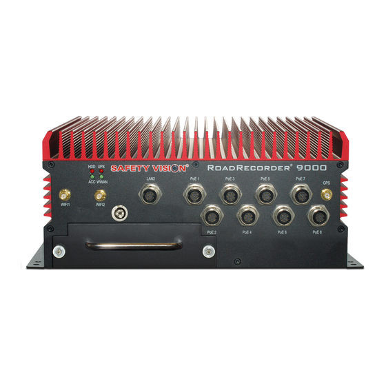
ROADRECORDER® 9000 USER GUIDE PART 1: HARDWARE Components Front Panel System Status LEDs: PoE 1 – PoE 8: • • 8-pin A-Code M12 Gigabit Power over Ethernet (PoE) NIC. ◦ BLINKS – When there is Reading and Writing Activity. • Type 2 Class 4 PoE (25.5-Watt 53VDC). -
Page 5: Rear Panel
ROADRECORDER® 9000 USER GUIDE Rear Panel Cellular Components: Grounding Stud: • SIM CARD – Cellular modem supported (not included). • Used for grounding NVR case to chassis. • ANT1 – Cellular Main antenna input. GPIO / COM3: HDMI Port: • Sub DB 15 Male Connection ◦... -
Page 6: Hard Drive Canister
ROADRECORDER® 9000 USER GUIDE Hard Drive Canister Status LEDs: • ◦ BLINKS – When there is Reading and Writing Activity. • ◦ SOLID – Power is being supplied. USB Port: • USB 3.0 port for connection to a PC. Data Port 1 / Data Port 2: •... -
Page 7: Wiring Diagram
ROADRECORDER® 9000 USER GUIDE Wiring Diagram... -
Page 8: Flat Mount Installation
ROADRECORDER® 9000 USER GUIDE Flat Mount Installation Secure the RoadRecorder 9000 NVR to the mounting surface using the appropriate fasteners. Ensure that the front panel of the NVR remains accessible, and that there is a minimum 2.5 inches of clearance for cables. -
Page 9: Removing / Inserting The Hard Drive
ROADRECORDER® 9000 USER GUIDE Removing / Inserting the Hard Drive To remove the hard drive from the NVR Ensure the NVR is powered OFF. 2. Insert the key into the hard drive lock and turn it counterclockwise. 3. Turn the two hard drive thumb screws counterclockwise until they are loose. 4. -
Page 10: Part 2: Configuration
ROADRECORDER® 9000 USER GUIDE PART 2: CONFIGURATION Installing SV Windows Application NOTE: Windows OS and SV Windows application are pre-installed prior to deployment, but there are some instances where the end user will want to do this themselves. If installing Windows OS yourself, Windows OS must be installed on the mSATA drive [internal SSD]. Windows OS must be installed prior to installing the SV Windows Application and any other applications. - Page 11 ROADRECORDER® 9000 USER GUIDE Step 2. Installing SV Windows Application Download and extract the SV Windows application from Safety Vision Technical Support. 2. Right-click the ‘SV_Setup’ file and select ‘Run as administrator’ to launch the SV Installer. If prompted by firewall or anti-virus application, allow the file to install.
-
Page 12: Launch The Sv Windows Application
ROADRECORDER® 9000 USER GUIDE Launch the SV Windows Application To access the NVR’s configuration menus, connect to the NVR and launch the SV Windows Application. There are two methods for connecting to the NVR and launching the SV Windows Application: Using a keyboard, mouse and monitor –... -
Page 13: Help Windows
ROADRECORDER® 9000 USER GUIDE Help Windows Each screen in the RoadRecorder 9000 NVR configuration interface includes a comprehensive help menu. The help menus explain the functionality and parameters of each field. To access the help menu for a screen, simply click the Help button at the top right of the screen. The help menu appears in a... -
Page 14: Firmware Configuration
ROADRECORDER® 9000 USER GUIDE Firmware Configuration The Firmware Configuration page allows you to import/export configuration files, update username and password, as well as reboot the NVR. Import/Export NVR Configuration Username / Password Configuration Users can import and export configuration files from this Users can update Username and Password from this section section. -
Page 15: Startup And Shutdown Settings
ROADRECORDER® 9000 USER GUIDE Startup and Shutdown Settings The Startup and Shutdown page allows you to configure startup and shutdown conditions of the NVR. Startup Schedule Reboot Select this option to enable the Startup Delay feature, where • Enable schedule reboot: If enabled, NVR will reboot on the NVR will wait for a set duration before starting up the selected day(s) and specified time. -
Page 16: Poe Settings
ROADRECORDER® 9000 USER GUIDE PoE Settings The PoE Settings page allows users to turn on/off the NVR’s PoE ports. PoE Control If PoE box is checked, PoE port is active and receiving power. By default, all PoE boxes are checked. To turn off power to a PoE port, uncheck the PoE box. -
Page 17: Input/Outputs
ROADRECORDER® 9000 USER GUIDE Input/Outputs The Sensor Input Output Settings page configures the NVR’s sensor inputs and relay outputs. • Digital Input: Sensor input number. • Digital Out: Relay output number. • Sensor Name: Enter a name for each sensor input in this •... -
Page 18: Recording Settings
ROADRECORDER® 9000 USER GUIDE Recording Settings The Recording Settings page configures where metadata files are stored and their retention period. Select directory to store metadata file Metadata Files Retention Period Click the Browse button and select the location to store Enter the amount of days, between 1 to 365 days, to Archive or... -
Page 19: Date / Time Settings
ROADRECORDER® 9000 USER GUIDE Date / Time Settings The Date / Time Settings page configures the NVR’s time zone. Timezone Select the appropriate time zone from the dropdown menu. Sync with GPS time Select this option to sync the NVR time with GPS time if it is giving valid data. Click Apply to save changed entries. -
Page 20: Diagnostics
ROADRECORDER® 9000 USER GUIDE Diagnostics The Diagnostics page provides detailed information regarding the current status of the NVR and the accessories connected to it. This information can be useful when troubleshooting certain issues. All fields in the Diagnostics page are for display only and cannot be changed. -
Page 21: Gps
ROADRECORDER® 9000 USER GUIDE The GPS page configures the GPS signal priority and shows the current GPS information. GPS Type NOTE: Page will refresh every 1 sec. • GPRMC: Recommended minimum specific GPS/Transit Use the dropdown menus in the Priority fields to select which data. -
Page 22: Appendix A: Specifications
ROADRECORDER® 9000 USER GUIDE Appendix A: Specifications PART NUMBER CANBUS/GPS MODULE (ACCELEROMETER AND GPS INCLUDED) 9000-NVR CANbus 2.0 a/b, OBD-II, J1939 and J1708 Built-in u-blox NEO-M8 GPS Module Untethered Dead Reckoning Technology OS SUPPORT Sensor Integrated: 3D Gyroscope, 3D Accelerometer Windows®... -
Page 23: Appendix B: Dimensions
ROADRECORDER® 9000 USER GUIDE Appendix B: Dimensions... -
Page 24: Fcc Compliance Statement
ROADRECORDER® 9000 USER GUIDE FCC Compliance Statement This device has been tested and found to comply with the limits for a Class A digital device, pursuant to part 15 of the FCC Rules. These limits are designed to provide reasonable protection against harmful interference when the equipment is operated in a commercial environment. - Page 25 CORPORATE HEADQUARTERS 6100 W. Sam Houston Pkwy. N. Houston, TX 77041-5113 Main: 713.896.6600 Toll Free: 800.880.8855 Fax: 713.896.6640 www.safetyvision.com...
Need help?
Do you have a question about the ROADRECORDER 9000 and is the answer not in the manual?
Questions and answers