Western Digital OpenFlex Data24 DCS0010 User Manual
Hide thumbs
Also See for OpenFlex Data24 DCS0010:
- Manual (39 pages) ,
- Installation manual (30 pages) ,
- Manual (44 pages)

Related Manuals for Western Digital OpenFlex Data24 DCS0010


Summary of Contents for Western Digital OpenFlex Data24 DCS0010
- Page 1 User Guide OpenFlex Data24 ™ Regulatory Model: DCS0010 1ET2228 Version 1.0 November 2020...
-
Page 2: Table Of Contents
User Guide Table of Contents Table of Contents Revision History............................ iv Notices..............................v Points of Contact..........................vi Chapter 1. Overview......................1 OpenFlex Data24 Overview.........................2 Design Details............................3 LEDs..............................4 Servicing Features.........................7 List of Compatible Devices......................... 7 Electrical Specifications........................8 Environmental Specifications......................8 Mechanical Specifications........................8 List of CRUs............................9 Rack Requirements.......................... - Page 3 User Guide Table of Contents PSU Specifications........................19 Rails..............................20 Rails Specification........................20 Chapter 3. Support......................21 Platform Details Pullout Tab......................22 Chassis Replacement......................... 22 Drive Assembly Replacement......................38 System Fan Replacement........................41 IO Module (IOM) Replacement......................48 Power Supply Unit (PSU) Replacement....................53 Rails Replacement..........................56 Chapter 4.
- Page 4 User Guide Table of Contents Electrostatic Discharge........................89 Optimizing Location...........................89 Power Connections..........................89 Power Cords............................89 Rackmountable Systems........................90 Restricted Access Location......................90 Safety and Service..........................90 Safety Warnings and Cautions......................91 Chapter 7. Regulatory....................92 Europe (CE Declaration of Conformity)....................93 FCC Class A Notice........................... 93 ICES-003 Class A Notice—Avis NMB-003, Classe A...............
-
Page 5: Revision History
User Guide Revision History Revision History Date Revision Comment November 2020 Initial Release... -
Page 6: Notices
Per Western Digital Terms and Conditions of Sale, the user of Western Digital products in life support applications assumes all risk of such use and indemnifies Western Digital against all damages. -
Page 7: Points Of Contact
Email: support@wdc.com Website: https:/ /portal.wdc.com/Support/s/ UK Import Representation Contact Western Digital UK Limited Hamilton House, Regent Park, Kingston Road Leatherhead, Surrey KT22 7PL, GB, United Kingdom Telephone: +44 1372 366000... -
Page 8: Chapter 1. Overview
Western Digital Overview In This Chapter: - OpenFlex Data24 Overview......2 - Design Details..........3 - List of Compatible Devices......7 - Electrical Specifications........ 8 - Environmental Specifications......8 - Mechanical Specifications......8 - List of CRUs............ 9 - Rack Requirements........11 - Space Requirements........12... -
Page 9: Openflex Data24 Overview
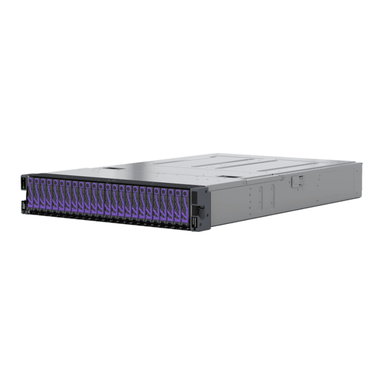
1.1 OpenFlex Data24 Overview The OpenFlex Data24 is a 2U rack mounted data storage enclosure built on the OpenFlex platform. OpenFlex is Western Digital’s architecture that supports Open Composable Infrastructure (OCI). The OpenFlex Data24 is a Just-a-Bunch-Of-Flash (JBOF) platform that leverages this OCI approach in the form of disagreggated data storage using NVMe-over-Fabrics (NVMe-oF™). -
Page 10: Design Details
1. Overview User Guide 1.2 Design Details 1.2 Design Details On the front of the OpenFlex Data24 there are the 24 Small Form Factor (SFF) drive slots, and the enclosure status LEDs. Each drive is individually removable/serviceable. Below each drive slot there are status and activity LEDs embedded in the chassis. -
Page 11: Leds
1. Overview User Guide 1.2 Design Details 1.2.1 LEDs Enclosure LEDs Figure 2: Enclosure LEDs Table 1: Enclosure LED Flash Patterns LED Name Color Behavior Identification White Blink @ 1 Hz: Blinks only when Identification has been activated. Will blink when any component is identified, e.g. - Page 12 1. Overview User Guide 1.2 Design Details Power Supply Unit (PSU) LED Figure 3: Power Supply Unit (PSU) LED Table 2: Power Supply Unit (PSU) LED Flash Patterns LED Name Color Behavior Multi- Green Solid: PSU is on and function LED reporting no faults Blinking @ 2Hz: PSU in firmware update...
- Page 13 1. Overview User Guide 1.2 Design Details Drive Assembly LEDs Figure 5: Drive Assembly LEDs Table 4: Drive Assembly LED Flash Patterns LED Name Color Behavior Status Green/Amber Green: Device is Powered On Flashing Green: Activity Amber: Device has fault Off: Device is Powered Down...
-
Page 14: Servicing Features
1. Overview User Guide 1.3 List of Compatible Devices LED Name Color/Number Behavior Power Green Solid: IOM is powered on Off:IOM is powered off Service State Blue Solid: IOM is serviceable Off: IOM is not serviceable Fault Amber Solid: Enclosure has a fault Off: IOM has no fault 1.2.2 ... -
Page 15: Electrical Specifications
1. Overview User Guide 1.4 Electrical Specifications Part Device Volume Drive Writes Encryption Bandwidth Number OpenFlex Data24 CRU Drive w/ 6.4TB 3.3GB/s RI-3DW/D 1EX2794 Carrier SN840 1.4 Electrical Specifications Table 7: Electrical Specifications Specification Value Max Power Consumption 2000W Typical Power Consumption ~410 W Input Voltage... -
Page 16: List Of Crus
1. Overview User Guide 1.7 List of CRUs Table 9: Mechanical Specifications Specification Non-Operational Operational Shock 10G, 11ms half sine; 3 5G, 11ms half sine; positive positive and 3 negative and 3 negative pulses pulses in X, Y, and Z axes. in X, Y, and Z axes. - Page 17 1. Overview User Guide 1.7 List of CRUs Component Part Number Package Dimensions Weight 1EX2701 OpenFlex Data24 CRU IO 3.6 kg / W: 292.1 mm x L: 469.9 mm x H: 203.2 mm Module w/3 Add-In Cards 8 lbs W: 11.5 in x L: 18.5 in x H: 8 in 1EX2702 OpenFlex Data24 5.4 kg /...
-
Page 18: Rack Requirements
1. Overview User Guide 1.8 Rack Requirements Component Part Number Package Dimensions Weight W: 6.7 in x L: 11.6 in x H: 3 in 1.8 Rack Requirements The OpenFlex Data24 is designed to be installed into a rack that meets the EIA-310 standard with a minimum of 1000 mm (39.4 in.) of usable rack space, door to door. -
Page 19: Space Requirements
711 mm / 27.99 in. of space in front of the rack to allow enough clearance to remove an enclosure. See the following diagram for details. 1.10 Supported SKUs The following table lists the versions of this Western Digital product that are supported by this document. Table 12: List of Supported SKUs Component... - Page 20 1. Overview User Guide 1.10 Supported SKUs Component Capacity OpenFlex Data24-12 SN840 6x100GbE nTAA PCIe RI-1DW/D SE 46.08TB 1ES2025 OpenFlex Data24-12 SN840 6x100GbE nTAA PCIe RI-1DW/D SE 92.16TB 1ES2026 OpenFlex Data24-12 SN840 6x100GbE nTAA PCIe RI-1DW/D SE 23.04 TB 1ES2027...
-
Page 21: Chapter 2. Components
Western Digital Components In This Chapter: - Chassis............15 - IO Module (IOM)..........16 - Drive Assembly..........17 - System Fan............ 18 - Power Supply Unit (PSU)......19 - Rails............... 20... -
Page 22: Chassis
2. Components User Guide 2.1 Chassis 2.1 Chassis The chassis is the primary housing that contains and connects all of the system components. All of the drives are located at the front in the drive bay, and the rear houses the IO Modules, PSUs, and cabling. There is a removable compartment cover on the top of the chassis that allows access to the system fans. -
Page 23: Io Module (Iom)
2. Components User Guide 2.2 IO Module (IOM) 2.2 IO Module (IOM) Each IOM provides system data connectivity through up to three QSFP28 cables per IOM, and supports cable lengths up to 5M. Out-of-Band Management (OOBM) features are accessed via an RJ45 port that supports a 10/100/1000 Ethernet connection. -
Page 24: Drive Assembly
2. Components User Guide 2.3 Drive Assembly 2.3 Drive Assembly The drive assembly is comprised of 3 basic parts: the 2.5 in. SSD, the drive carrier, and the interposer card. The drive carrier houses the 2.5 in. drive and the interposer card and enables toolless installation and replacement. -
Page 25: System Fan
2. Components User Guide 2.4 System Fan 2.4 System Fan The system fans provide the primary system cooling for the OpenFlex Data24. There are five fans total, and they are accessible from a latch cover on the top of the chassis. The system fans are hotswappable CRU components, and do not require any wiring. -
Page 26: Power Supply Unit (Psu)
2. Components User Guide 2.5 Power Supply Unit (PSU) 2.5 Power Supply Unit (PSU) The Power Supply Units (PSUs) inside the OpenFlex Data24 are 2000W, 80 Plus Platinum efficiency rated, and operates within a 200 - 240 VAC voltage range. The PSUs are redundant and can be hotswapped one at a time. -
Page 27: Rails
2. Components User Guide 2.6 Rails 2.6 Rails The Rails included with the OpenFlex Data24 are 2U, shelf style rails with springloaded inner arms that enable easy installation. 2.6.1 Rails Specification Table 18: Rails Specification Summary Specification Value Part Number 1EX2702 Number per Enclosure... -
Page 28: Chapter 3. Support
Western Digital Support In This Chapter: - Platform Details Pullout Tab......22 - Chassis Replacement........22 - Drive Assembly Replacement..... 38 - System Fan Replacement......41 - IO Module (IOM) Replacement....48 - Power Supply Unit (PSU) Replacement..53... -
Page 29: Platform Details Pullout Tab
3. Support User Guide 3.1 Platform Details Pullout Tab 3.1 Platform Details Pullout Tab There is a small plastic tab that can be pulled out to show the vital system details such as the SKU number and serial numbers. The pullout tab is located on the front of the platform in the location shown in the following image. - Page 30 3. Support User Guide 3.2 Chassis Replacement Step 1 : Unpack and inspect the new Chassis for damage. a. Inspect the packaging that the Chassis replacement was shipped in and record any damage to the box. Large cuts, open boxes, and crushed corners should be reported. b.
- Page 31 3. Support User Guide 3.2 Chassis Replacement Figure 16: Disconnect RJ45 Ethernet Cables d. Disconnect the QSFP28 cables from all of the IOM ports. Figure 17: Disconnect QSFP28 Cables Remember: Its important to return drives to their proper slot when reinstalling. Use a tracking methodology such as marking drive assemblies to be certain that drive assemblies removed by this procedure make it back to their correct slot number.
- Page 32 3. Support User Guide 3.2 Chassis Replacement Figure 18: Drive Assembly Release Operation b. Use the release handle to pull the Drive Assembly out of the enclosure. Figure 19: Uninstall Drive Assembly Step 4 : Uninstall each Drive Assembly in the same way the first was uninstalled. Caution: The PSU must be replaced within 5 minutes.
- Page 33 3. Support User Guide 3.2 Chassis Replacement Figure 20: Power Supply Unit (PSU) Release Latch Operation b. Carefully pull the Power Supply Unit (PSU) out of the Power Supply Unit (PSU) slot. Figure 21: Uninstall Power Supply Unit (PSU) Step 6 : Uninstall the remaining Power Supply Unit (PSU) in the same way the first was uninstalled. Step 7 : Uninstall the IO Module (IOM) from the enclosure.
- Page 34 3. Support User Guide 3.2 Chassis Replacement Figure 22: IO Module (IOM) Thumbscrew Operation b. Pull the release handle out until the IO Module (IOM) is unseated and can be removed from the IO Module (IOM) slot. Figure 23: IO Module (IOM) Release Handle Operation Figure 24: Uninstall IO Module (IOM) Step 8 : Uninstall the remaining IO Module (IOM) in the same way the first was uninstalled.
- Page 35 3. Support User Guide 3.2 Chassis Replacement a. From the front of the rack, using the T15 Torx screwdriver, loosen the two Torx captive screws that secure the Chassis to the rail. Repeat this step to loosen the two Torx captive screws that secure the Chassis to the remaining rail.
- Page 36 3. Support User Guide 3.2 Chassis Replacement Figure 26: Locking Tabs d. Continue sliding the chassis out of the rack and ensure extra care is taken to support the weight of the Chassis when the Chassis is clear of the rack mount rails. Figure 27: Uninstall Chassis Step 10 : Install the Chassis onto the rack mounted rails.
- Page 37 3. Support User Guide 3.2 Chassis Replacement a. Carefully slide the Chassis onto the rails until the rack ears are flush with the mounts on the rails. Figure 28: Chassis Installation b. Using the T15 Torx screwdriver, tighten the two Torx captive screws to secure the Chassis to the rail.
- Page 38 3. Support User Guide 3.2 Chassis Replacement Figure 29: Captive Screws Step 11 : Install the IO Module (IOM) into the enclosure. a. From the rear of the rack, unlock the IO Module (IOM) by turning the thumbscrew counterclockwise until the screw threads are not engaged any longer. The location of the thumbscrew is shown in the following image.
- Page 39 3. Support User Guide 3.2 Chassis Replacement Figure 30: Prepare IO Module (IOM) b. Gently slide the IO Module (IOM) into the IO Module (IOM) slot until the release handle is engaged with the Chassis. When the handle lifts up slightly, it is an indicator that the release handle is engaged with the Chassis.
- Page 40 3. Support User Guide 3.2 Chassis Replacement Figure 31: IO Module (IOM) Handle Engaged c. Press the release handle into the IO Module (IOM) and secure it in place by turning the thumbscrew clockwise until it is tight. Figure 32: IO Module (IOM) Secure d.
- Page 41 3. Support User Guide 3.2 Chassis Replacement Step 12 : Install the remaining IO Module (IOM) in the same way the first was installed. Step 13 : Install the Power Supply Unit (PSU) into the enclosure. a. Orient the Power Supply Unit (PSU) with the power port located on the top and insert it into the Power Supply Unit (PSU) slot.
- Page 42 3. Support User Guide 3.2 Chassis Replacement Figure 35: Drive Assembly Release Operation b. From the front of the rack, gently slide the Drive Assembly into the Drive Assembly slot until the release handle lifts up slightly, indicating that it is engaged with the Chassis. Figure 36: Drive Assembly Latch Engaged c.
- Page 43 3. Support User Guide 3.2 Chassis Replacement Figure 37: Drive Assembly Installation Step 16 : Install the remaining Drive Assembly in the same way the first was installed. Step 17 : Connect the power and data cables to the enclosure. a. Loop the PSU's retention clip around the power cable and pinch it until the clip catches and locks in place.
- Page 44 3. Support User Guide 3.2 Chassis Replacement Figure 39: Sliding the Retention Clip Forward c. Connect the Ethernet Cable into the Ethernet Management port. Figure 40: Connecting RJ45 Ethernet Cable to Management Port d. Connect the QSFP28 cables into all of the IOM ports. Figure 41: Connect QSFP28 Cables e.
-
Page 45: Drive Assembly Replacement
3. Support User Guide 3.3 Drive Assembly Replacement Figure 42: Connect Power Cables f. Wrap the power cable in the cable retention clip and cinch it so it securely holds the power cable in place. Figure 43: Cinching Retention Strap (Generic PSU Shown) 3.3 ... - Page 46 3. Support User Guide 3.3 Drive Assembly Replacement a. Inspect the packaging that the Drive Assembly replacement was shipped in and record any damage to the box. Large cuts, open boxes, and crushed corners should be reported. b. Remove the Drive Assembly from the packaging and verify that there is no damage to the Drive Assembly.
- Page 47 3. Support User Guide 3.3 Drive Assembly Replacement Figure 45: Uninstall Drive Assembly Step 3 : Install the Drive Assembly into the enclosure. a. Prepare the Drive Assembly for installation by pressing the release button on the front of the Drive Assembly. The release handle will eject outward. Figure 46: Drive Assembly Release Operation b.
-
Page 48: System Fan Replacement
3. Support User Guide 3.4 System Fan Replacement Figure 47: Drive Assembly Latch Engaged c. Rotate the release handle up and press it into the Drive Assembly to secure it into the slot. When it is fully installed the user will feel the handle snap and lock into place. Figure 48: Drive Assembly Installation 3.4 ... - Page 49 3. Support User Guide 3.4 System Fan Replacement Required vs. Tool # Needed Recommended T15 Torx Screwdriver Required ESD Mitigation Equipment (site specific) Required • ESD Sensitive • Electric Shock • Fan Blade Danger Step 1 : Unpack and inspect the new System Fan for damage. a.
- Page 50 3. Support User Guide 3.4 System Fan Replacement b. Carefully slide the Chassis out of the rack until the System Fan bay is completely accessible and the locking tabs on the side of the chassis have stopped the OpenFlex Data24 and locked it in place.
- Page 51 3. Support User Guide 3.4 System Fan Replacement Figure 52: System Fan Bay Cover Operation b. Gain access to the System Fan bay by lifting the flexible label. Figure 53: Flexible Label c. Grasp the System Fan firmly with your index finger and use your thumb to press the latch release using a pinching motion.
- Page 52 3. Support User Guide 3.4 System Fan Replacement Figure 54: System Fan Latch Operation Caution: The fan module must be replaced within 5 minutes. Carefully pull the System Fan out of the System Fan slot. Figure 55: Uninstall System Fan Step 4 : Install the System Fan into the enclosure.
- Page 53 3. Support User Guide 3.4 System Fan Replacement Figure 56: Flexible Label b. Orient the System Fan with the module latch (and connector) on the right-hand side and insert it into the System Fan slot. Figure 57: System Fan Installation...
- Page 54 3. Support User Guide 3.4 System Fan Replacement Figure 58: System Fan Installation c. Verify that the System Fan is fully seated and latched into the System Fan slot by gently pulling on the module. d. Latch the System Fan bay cover by rotating the cover toward the Chassis and sliding both latches in towards the center of the Chassis until the cover engages with the Chassis.
- Page 55 3. Support User Guide 3.4 System Fan Replacement a. Carefully slide the Chassis into the rack until the rack ears are flush with the mounts on the rails. Figure 60: Seating the Chassis b. Using the T15 Torx screwdriver, tighten the two Torx captive screws to secure the Chassis to the rail.
-
Page 56: Io Module (Iom) Replacement
3. Support User Guide 3.5 IO Module (IOM) Replacement 3.5 IO Module (IOM) Replacement Replacement Requirements Personnel Required Service Window No Service Window Tool # Needed Required vs. Optional Philips head Screwdriver Optional • ESD Sensitive • Electric Shock Step 1 : Unpack and inspect the new IO Module (IOM) for damage. - Page 57 3. Support User Guide 3.5 IO Module (IOM) Replacement Figure 63: IO Module (IOM) Release Handle Operation Figure 64: Uninstall IO Module (IOM) Step 3 : Install the IO Module (IOM) into the enclosure. a. From the rear of the rack, unlock the IO Module (IOM) by turning the thumbscrew counterclockwise until the screw threads are not engaged any longer.
- Page 58 3. Support User Guide 3.5 IO Module (IOM) Replacement Figure 65: Prepare IO Module (IOM) b. Gently slide the IO Module (IOM) into the IO Module (IOM) slot until the release handle is engaged with the Chassis. When the handle lifts up slightly, it is an indicator that the release handle is engaged with the Chassis.
- Page 59 3. Support User Guide 3.5 IO Module (IOM) Replacement Figure 66: IO Module (IOM) Handle Engaged c. Press the release handle into the IO Module (IOM) and secure it in place by turning the thumbscrew clockwise until it is tight. Figure 67: IO Module (IOM) Secure d.
-
Page 60: Power Supply Unit (Psu) Replacement
3. Support User Guide 3.6 Power Supply Unit (PSU) Replacement Step 4 : Connect the data cables to the IO Module (IOM). 3.6 Power Supply Unit (PSU) Replacement Replacement Requirements Personnel Required Service Window 5 minutes • ESD Sensitive • Electric Shock •... - Page 61 3. Support User Guide 3.6 Power Supply Unit (PSU) Replacement Figure 69: Power Supply Unit (PSU) Release Latch Operation b. Carefully pull the Power Supply Unit (PSU) out of the Power Supply Unit (PSU) slot. Figure 70: Uninstall Power Supply Unit (PSU) Step 4 : Install the Power Supply Unit (PSU) into the enclosure.
- Page 62 3. Support User Guide 3.6 Power Supply Unit (PSU) Replacement Figure 71: Port Location Figure 72: Power Supply Unit (PSU) Installation b. Verify that the Power Supply Unit (PSU) is fully seated and latched into the Power Supply Unit (PSU) slot by gently pulling on the handle. Step 5 : Connect the power cable to the Power Supply Unit (PSU).
-
Page 63: Rails Replacement
3. Support User Guide 3.7 Rails Replacement Figure 73: Connect Power Cable 3.7 Rails Replacement Replacement Requirements Personnel Required Service Window Tool # Needed Required vs. Optional T15 Torx Screwdriver Required Level Optional Lift Equipment Optional ESD Mitigation Equipment (site specific) Required •... - Page 64 3. Support User Guide 3.7 Rails Replacement Figure 74: Unclipping Cable Retention Strap (Generic PSU Shown) b. Move to the rear of the rack and disconnect the power cables from each of the two Power Supply Unit (PSU). Figure 75: Disconnect Power Cables c.
- Page 65 3. Support User Guide 3.7 Rails Replacement Figure 76: Disconnect RJ45 Ethernet Cables d. Disconnect the QSFP28 cables from all of the IOM ports. Figure 77: Disconnect QSFP28 Cables Step 3 : Uninstall the Chassis from the rack mounted rails. a. From the front of the rack, using the T15 Torx screwdriver, loosen the two Torx captive screws that secure the Chassis to the rail.
- Page 66 3. Support User Guide 3.7 Rails Replacement Figure 78: Rack Ear Captive Screw Location b. Carefully pull the Chassis out of the rack. The chassis will slide out of the rails until the locking tabs on the side of the chassis engage and stop the chassis from being pulled out further.
- Page 67 3. Support User Guide 3.7 Rails Replacement Figure 79: Locking Tabs d. Continue sliding the chassis out of the rack and ensure extra care is taken to support the weight of the Chassis when the Chassis is clear of the rack mount rails. Figure 80: Uninstall Chassis...
- Page 68 3. Support User Guide 3.7 Rails Replacement Step 4 : Uninstall the rack mount Rails. a. From the front of the rack, using the T15 Torx screwdriver, uninstall the M5 Torx screw that secure the front of the rack mount Rails and bracket to the rack. Figure 81: Uninstall Front Rack Mount b.
- Page 69 3. Support User Guide 3.7 Rails Replacement Figure 82: Uninstall Rear Rack Mount Figure 83: Remove Rail...
- Page 70 3. Support User Guide 3.7 Rails Replacement Step 5 : Uninstall the remaining Rails in the same way the first was uninstalled. Step 6 : Install the rack mount Rails. a. Determine which of the rails is the right and which is the left as shown in the following image.
- Page 71 3. Support User Guide 3.7 Rails Replacement Figure 86: Install Rear Rack Mount d. From the front of the rack, using the T15 Torx screwdriver, install the M5 Torx screws that secure the front of the rack mount Rails and bracket to the rack.
- Page 72 3. Support User Guide 3.7 Rails Replacement Figure 87: Install Front Rack Mount Step 7 : Install the remaining Rails in the same way the first was installed. Step 8 : Install the Chassis onto the rack mounted rails. a. Carefully slide the Chassis onto the rails until the rack ears are flush with the mounts on the rails.
- Page 73 3. Support User Guide 3.7 Rails Replacement Figure 88: Chassis Installation b. Using the T15 Torx screwdriver, tighten the two Torx captive screws to secure the Chassis to the rail. Repeat this step to secure the remaining rack mount to the remaining rail.
- Page 74 3. Support User Guide 3.7 Rails Replacement Figure 89: Captive Screws Step 9 : Connect the power and data cables to the enclosure. a. Loop the PSU's retention clip around the power cable and pinch it until the clip catches and locks in place.
- Page 75 3. Support User Guide 3.7 Rails Replacement Figure 91: Sliding the Retention Clip Forward c. Connect the Ethernet Cable into the Ethernet Management port. Figure 92: Connecting RJ45 Ethernet Cable to Management Port d. Connect the QSFP28 cables into all of the IOM ports. Figure 93: Connect QSFP28 Cables e.
- Page 76 3. Support User Guide 3.7 Rails Replacement Figure 94: Connect Power Cables f. Wrap the power cable in the cable retention clip and cinch it so it securely holds the power cable in place. Figure 95: Cinching Retention Strap (Generic PSU Shown)
-
Page 77: Chapter 4. Management
Western Digital Management In This Chapter: - Open Composable API......... 71 - In-band Enclosure Management....71 - NVMe-CLI............71 - Downloading Firmware from the Support Portal............... 76 - Enclosure Firmware Update......78 - Drive Firmware Upgrade......80... -
Page 78: Open Composable Api
4. Management User Guide 4.1 Open Composable API 4.1 Open Composable API The Open Composable API is a RESTful interface for OpenFlex that enables a Unified Fabric Control Plane for Storage Fabric Devices. This allows for composing disaggregated storage resources—with compute, networking, and memory—into virtual systems in the future. -
Page 79: Discovering And Connecting To Nvme™ Devices On Openflex Data24
4. Management User Guide 4.3 NVMe-CLI Note: OpenFlex Data24 supports only version 1.12 of NVMe-CLI To install NVMe-CLI on Ubuntu 18.04.4 LTS: sudo apt-get install -y nvme-cli To Install NVMe-CLI on CentOS 7.7, 8.1/RHEL 7.7, 8.2: sudo yum install nvme-cli For further details on NVMe-CLI see the following resources: •... - Page 80 4. Management User Guide 4.3 NVMe-CLI "URI": "/Query/", "TimeoutMultiplier": 1, "Version": "1.2.0-301" "Devices": { "Self": "http://10.20.30.40:80/Devices/", "Members": [ "Self": "http://10.20.30.40:80/Storage/Devices/openflex- data24-usalp00000aa000a/", "SystemType": { "ID": 2, "Name": "Storage" "Name": "openflex-data24-usalp00000aa000a", "ID": "openflex-data24-usalp00000aa000a", "OperatingSystem": { "Self": "http://10.20.30.40:80/Storage/Devices/ openflex-data24-usalp00000aa000a/OperatingSystem/", "Name": "Vendor Firmware", "OSType": { "ID": 59, Truncated Example c.
- Page 81 4. Management User Guide 4.3 NVMe-CLI e. Determine the IP address of the adapter that is attached to your host using the ports link. This will be the IP that is used to perform an to find drives connected on nvme discover the fabric.
- Page 82 4. Management User Guide 4.3 NVMe-CLI Step 3 : Review the output to locate the subnqn number associated with the device that will be connected. The following example shows two devices, the In-Band management device, as well as the device intended for connection. Discovery Log Number of Records 2, Generation counter 0 =====Discovery Log Entry 0====== trtype:...
-
Page 83: Downloading Firmware From The Support Portal
/portal.wdc.com/Support/s/. The Western Digital Enterprise Support Center will appear. Step 2 : Log in to the Western Digital Enterprise Support Center using a valid email address and password: Several support options will appear on the page. Step 3 : Click the Downloads option: The Western Digital downloads page will appear. - Page 84 4. Management User Guide 4.4 Downloading Firmware from the Support Portal The Select Files for Download section updates with the applicable options: Step 5 : From the Select Files for Download section, expand the Firmware option and select the checkbox for the appropriate firmware file(s): Note: Filenames will vary, depending on the options chosen in the Identify Product section.
-
Page 85: Enclosure Firmware Update
4. Management User Guide 4.5 Enclosure Firmware Update Step 7 : If needed, remove an unwanted file by clicking its red X. Step 8 : Select the appropriate archive file format by clicking either Zip or Tar. Step 9 : Click the Download Files button to download the selected files. Step 10 : If needed, unzip/extract the file to the desired location. - Page 86 4. Management User Guide 4.5 Enclosure Firmware Update Transfer-Encoding: chunked Step 4 : Using the Etag from the GET request, issue a PUT request to the same resource, passing the key/ value pair of to update the firmware: "FirmwareUpdate":true curl -v -u <username>:<password> -X PUT -H "If- Match:783e532540dc6b3e4978604a2f3e0353"...
-
Page 87: Drive Firmware Upgrade
4. Management User Guide 4.6 Drive Firmware Upgrade "Self": "http://10.202.249.35:80/Storage/Devices/openflex-data24- usalp03020qb0003-ioma/Jobs/FirmwareActivate/", "ID": "FirmwareActivate", "PercentComplete": 100, Step 8 : Repeat these steps to update firmware for the second IO Module (IOM). Note: For high availability, it is recommended to update one IO Module (IOM) at a time. -
Page 88: Chapter 5. Configuration
Western Digital Configuration In This Chapter: - Device Installation Order......82 - Initial Network Configuration..... 83 - Setting Static IPs on Ports......83 - Port Setup Using Bash Script......86... -
Page 89: Device Installation Order
5. Configuration User Guide 5.1 Device Installation Order 5.1 Device Installation Order The OpenFlex Data24 holds 1-24 storage drive assemblies. The minimum number of drives required is 1, and drives can be installed in increments of 1 at a time. However, there is a specific installation order that is recommended in order to optimally balance data load distribution. -
Page 90: Initial Network Configuration
5. Configuration User Guide 5.2 Initial Network Configuration 5.2 Initial Network Configuration This section outlines the behavior of the OpenFlex Data24 when it is initially connected to a network. The default configuration for the RJ45 management ports and the QSFP28 data ports will be to initially attempt a network configuration using DHCP. - Page 91 5. Configuration User Guide 5.3 Setting Static IPs on Ports Step 1 : Drill down into the OCAPI to access each Port object. Step 2 : Do a GET to the IOMs /query/ object to get the adapter addresses. curl -i -u user:password http://10.20.30.40/query/ Step 3 : Use the device URL obtained in the previous step to find the URLs for all of the Adapters in the IOM.
- Page 92 5. Configuration User Guide 5.3 Setting Static IPs on Ports "AddressOrigin": { "ID": 65536, "Name": "DHCPv4" "IPv4Address": "10.202.249.56/24", "IPv4Gateway": "10.202.249.1", "MACAddress": "00:0c:ca:11:00:40", "NetworkType": { "ID": 8, "Name": "IPv4 Network" "MTUBytes": 1500, "Controllers": "http://10.202.249.56:80/Storage/Devices/openflex-data24- usalp03420xxxxxx/Controllers/?portid=00_0c_ca_11_00_40_10_202_249_56_24" Step 7 : Send a HEAD to the Port object you wish to configure to secure the Etag for authorization purposes.
-
Page 93: Port Setup Using Bash Script
5. Configuration User Guide 5.4 Port Setup Using Bash Script "NetworkType": { "ID": 8, "Name": "IPv4 Network" "MTUBytes": 1500, "Controllers": "http://10.202.249.56:80/Storage/Devices/openflex-data24- usalp03420xxxxxx/Controllers/?portid=00_0c_ca_11_00_40_10_202_249_56_24" 5.4 Port Setup Using Bash Script Users can leverage a Bash script available with the OpenFlex Data24 firmware package available at https:/ / portal.wdc.com/Support/s/. - Page 94 5. Configuration User Guide 5.5 Installing Standalone OCAPI for In-Band Management sudo nvme id-ctrl /dev/nvm#...
-
Page 95: Chapter 6. Safety
Western Digital Safety In This Chapter: - Electrostatic Discharge....... 89 - Optimizing Location........89 - Power Connections........89 - Power Cords..........89 - Rackmountable Systems......90 - Restricted Access Location......90 - Safety and Service........90 - Safety Warnings and Cautions....91... -
Page 96: Electrostatic Discharge
6.1 Electrostatic Discharge 6.1 Electrostatic Discharge CAUTION: Electrostatic discharge can harm delicate components inside Western Digital products. Electrostatic discharge (ESD) is a discharge of stored static electricity that can damage equipment and impair electrical circuitry. It occurs when electronic components are improperly handled and can result in complete or intermittent failures. -
Page 97: Rackmountable Systems
6. Safety User Guide 6.5 Rackmountable Systems Use only tested and approved power cords to connect to properly grounded power outlets or insulated sockets of the rack's internal power supply. If an AC power cord was not provided with your product, purchase one that is approved for use in your country or region. -
Page 98: Safety Warnings And Cautions
All maintenance and service actions appropriate to the end-users are described in the product documentation. All other servicing should be referred to an Western Digital-authorized service technician. To avoid shock hazard, turn off power to the unit by unplugging both power cords before servicing the unit. -
Page 99: Chapter 7. Regulatory
Western Digital Regulatory In This Chapter: - Europe (CE Declaration of Conformity)..93 - FCC Class A Notice........93 - ICES-003 Class A Notice—Avis NMB-003, Classe A............93 - Japanese Compliance Statement, Class A ITE..............93 - Taiwan Warning Label Statement, Class A... -
Page 100: Europe (Ce Declaration Of Conformity)
European Union, including the Electromagnetic Compatibility Directive (2014/30/EU), the Low Voltage Directive (2014/30/EU), RoHS Directive (2011/65/EU) and EcoDesign Directive (2019/424/EU). A “Declaration of Conformity” in accordance with the applicable directives has been made and is on file at Western Digital Technologies, Inc. Europe. -
Page 101: Taiwan Warning Label Statement, Class A Ite
7. Regulatory User Guide 7.5 Taiwan Warning Label Statement, Class A ITE This is a Class A product based on the Technical Requirement of the Voluntary Control Council for Interference by Information Technology (VCCI). In a domestic environment, this product may cause radio interference, in which case the user may be required to take corrective actions.
Need help?
Do you have a question about the OpenFlex Data24 DCS0010 and is the answer not in the manual?
Questions and answers