Page 1
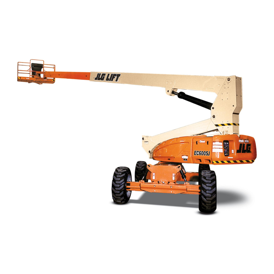
Operation and Safety Manual Original Instructions - Keep this manual with the machine at all times. Models EC600SJ H600SJ EC600SJP H600SJP PVC 2001 AS/NZS ANSI 31215027 April 21, 2020 - Rev B ®...
Page 2
@ www.discount-equipment.com Select an option below to find your Equipment We sell worldwide for the brands: Genie, Terex, JLG, MultiQuip, Mikasa, Essick, Whiteman, Mayco, Toro Stone, Diamond Products, Generac Magnum, Airman, Haulotte, Barreto, Power Blanket, Nifty Lift, Atlas Copco, Chicago Pneumatic, Allmand, Miller Curber, Skyjack, Lull,...
Page 3
WARNING Operating, servicing and maintaining this vehicle or equipment can expose you to chemicals including engine exhaust, carbon monoxide, phthalates, and lead, which are known to the State of California to cause cancer and birth defects or other reproductive harm. To minimize exposure, avoid breathing exhaust, do not idle the engine except as necessary, service your vehicle or equipment in a well-ventilated area and wear gloves or wash your hands frequently when servicing.
Page 4
The purpose of this manual is to provide owners, users, operators, lessors, and lessees with the precautions and operating procedures essential for the safe and proper machine operation for its intended purpose. Due to continuous product improvements, JLG Industries, Inc. reserves the right to make specification changes without prior notification. Contact JLG Industries, Inc. for updated information.
Page 5
FOREWORD SAFETY ALERT SYMBOLS AND SAFETY SIGNAL WORDS This is the Safety Alert Symbol. It is used to alert you to the potential personal injury hazards. Obey all safety messages that follow this symbol to avoid possible injury or death. INDICATES A POTENTIALLY HAZARDOUS SITUATION.
Page 6
FOREWORD REVISION LOG Original Issue A - November 25, 2019 Revision B - April 21, 2020 31215027...
This section contains the responsibilities of the owner, user, oper- ator, lessor, and lessee concerning safety, training, inspection, maintenance, application, and operation. If there are any ques- tions with regard to safety, training, inspection, maintenance, application, and operation, please contact JLG Industries, Inc. (“JLG”). 31215027...
MEWP. The user shall deter- ment unless the application is approved in writing by JLG. mine if personnel are qualified to operate the MEWP prior to operation.
• Check the machine for modifications to original components. opposite direction. Always return switch to neutral and stop Ensure that any modifications have been approved by JLG. before moving the switch to the next function. Operate con- trols with slow and even pressure.
• Hydraulic cylinders are subject to thermal expansion and con- traction. This may result in changes to the platform position approved by JLG. while the machine is stationary. Factors affecting thermal • When two or more persons are in the platform, the operator movement can include the length of time the machine will shall be responsible for all machine operations.
SECTION 1 - SAFETY PRECAUTIONS Electrocution Hazards • Enter and exit only through gate area. Use extreme caution when entering or leaving platform. Ensure that the platform • This machine is not insulated and does not provide protection assembly is fully lowered. Face the platform when entering or from contact or proximity to electrical current.
SECTION 1 - SAFETY PRECAUTIONS Table 1-1. Minimum Approach Distances (M.A.D.) Voltage Range MINIMUM APPROACH DISTANCE (Phase to Phase) in Feet (Meters) 0 to 50 KV 10 (3) Over 50KV to 200 KV 15 (5) Over 200 KV to 350 KV 20 (6) Over 350 KV to 500 KV 25 (8)
SECTION 1 - SAFETY PRECAUTIONS Tipping Hazards • The minimum approach distance may be reduced if insulating barriers are installed to prevent contact, and the barriers are • Ensure that the ground conditions are adequate to support rated for the voltage of the line being guarded. These barriers the maximum tire load indicated on the tire load decals shall not be part of (or attached to) the machine.
Page 19
Keep all loads within the confines of the plat- weather events, the time required to lower the platform, and form, unless authorized by JLG. methods to monitor current and potential wind conditions. • Keep the chassis of the machine a minimum of 2 ft. (0.6m) •...
SECTION 1 - SAFETY PRECAUTIONS DO NOT OPERATE THE MACHINE WHEN WIND CONDITIONS EXCEED SPECIFICATIONS SHOWN IN SECTION 7.2 OR AS SHOWN ON THE CAPACITY PLACARD ON THE PLAT- FORM BILLBOARD. Table 1-2. Beaufort Scale (For Reference Only) Wind Speed Beaufort Description Land Conditions...
SECTION 1 - SAFETY PRECAUTIONS Crushing and Collision Hazards • Keep non-operating personnel at least 6 ft. (1.8m) away from machine during all operations. • Approved head gear must be worn by all operating and • Under all travel conditions, the operator must limit travel ground personnel.
SECTION 1 - SAFETY PRECAUTIONS TOWING, LIFTING, AND HAULING MAINTENANCE • Never allow personnel in platform while towing, lifting, or This sub-section contains general safety precautions which must hauling. be observed during maintenance of this machine. Additional pre- cautions to be observed during machine maintenance are •...
• Use only replacement parts or components that are approved • Always disconnect batteries when servicing electrical compo- by JLG. To be considered approved, replacement parts or com- nents or when performing welding on the machine. ponents must be identical or equivalent to original parts or components.
SECTION 2 - USER RESPONSIBILITIES, MACHINE PREPARATION, AND INSPECTION SECTION 2. USER RESPONSIBILITIES, MACHINE PREPARATION, AND INSPECTION 2.1 PERSONNEL TRAINING The safest means to operate the machine where overhead obstructions, other moving equipment, and obstacles, The Mobile Elevating Work Platform (MEWP) is a personnel han- depressions, holes, and drop-offs exist.
JLG INDUSTRIES, INC. RECOGNIZES A FACTORY TRAINED SERVICE TECHNICIAN AS A Prior to users authorization of an operator to use a specific model of PERSON WHO HAS SUCCESSFULLY COMPLETED THE JLG SERVICE TRAINING SCHOOL MEWP, the user shall ensure the operator is familiarized on the follow- FOR THE SPECIFIC JLG PRODUCT MODEL.
Inspection forms are available from JLG. Use the Service and Maintenance Manual to perform inspections. JLG INDUSTRIES, INC. RECOGNIZES A FACTORY TRAINED SERVICE TECHNICIAN AS A PERSON WHO HAS SUCCESSFULLY COMPLETED THE JLG SERVICE TRAINING SCHOOL FOR THE SPECIFIC JLG PRODUCT MODEL.
Page 27
SECTION 2 - USER RESPONSIBILITIES, MACHINE PREPARATION, AND INSPECTION 1. Battery Pack 2. Fuel Tank 3. Hydraulic Tank 4. Main Terminal Box 5. Swing Drive 6. Turntable Lock 7. Frame 8. Turntable 9. Battery Charger 10. Generator Control Module (H Models) Figure 2-1.
Page 28
SECTION 2 - USER RESPONSIBILITIES, MACHINE PREPARATION, AND INSPECTION 1. Frame 2. Main Valve 3. Generator Start Battery (H Models) 4. Generator (H Models) 5. Battery Pack 6. Ground Control 7. Turntable Figure 2-2. Basic Nomenclature - Sheet 2 of 3 31215027...
Page 29
SECTION 2 - USER RESPONSIBILITIES, MACHINE PREPARATION, AND INSPECTION 31215027...
SECTION 2 - USER RESPONSIBILITIES, MACHINE PREPARATION, AND INSPECTION Pre-Start Inspection Fuel (Combustion Engine Powered Machines) – Add the proper fuel as necessary. The Pre-Start Inspection should include each of the following: Hydraulic Oil – Check the hydraulic oil level. Ensure hydrau- Cleanliness –...
SECTION 2 - USER RESPONSIBILITIES, MACHINE PREPARATION, AND INSPECTION GENERAL Platform Control Console - Switches and levers return to neutral when activated and released, decals/placards secure Begin your Walk-Around Inspection at item 1, as noted on the and legible, control markings legible. diagram.
Page 33
SECTION 2 - USER RESPONSIBILITIES, MACHINE PREPARATION, AND INSPECTION Ground Control Console - Switches and levers return to neutral when activated and released, decals/placards secure and legible, control markings legible. Battery Compartment - Batteries have proper electrolyte level; cables tight; no visible damage or corrosion. Fuel Tank - See Inspection Note.
SECTION 2 - USER RESPONSIBILITIES, MACHINE PREPARATION, AND INSPECTION Function Check From the platform control console: a. Ensure that the control console is firmly secured in the proper location b. Check that all guards protecting the switches or locks TO AVOID SERIOUS INJURY, DO NOT OPERATE MACHINE IF ANY CONTROL LEVERS OR are in place.
SECTION 2 - USER RESPONSIBILITIES, MACHINE PREPARATION, AND INSPECTION SkyGuard Function Test Disengage the SkyGuard sensor, release controls, then recy- cle the footswitch. Ensure normal operation is available. NOTE: Refer to Section 4.11 for additional information on SkyGuard NOTE: On machines equipped with SkyLine, reattach magnetic end of operation.
SECTION 3 - MACHINE CONTROLS AND INDICATORS SECTION 3. MACHINE CONTROLS AND INDICATORS GENERAL CONTROLS AND INDICATORS NOTE: The indicator panels use different shaped symbols to alert the operator to different types of operational situations that could THE MANUFACTURER HAS NO DIRECT CONTROL OVER MACHINE APPLICATION AND arise.
SECTION 3 - MACHINE CONTROLS AND INDICATORS NOTE: The optional generator engine will automatically shut down Platform Rotate under the following conditions: Provides rotation of the platform. Batteries Fully Charged High Oil Temperature Low Oil Pressure Engine Overspeed Overvoltage Jib Rotate (If Equipped) NOTE: The optional generator engine will not start if the batteries are Provides rotation of the jib and platform.
Page 39
SECTION 3 - MACHINE CONTROLS AND INDICATORS Jib Lift (If Equipped) Power/Emergency Stop Provides raising and lowering of the jib. A two-position red mushroom shaped switch furnishes power to Platform/Ground Select switch when pulled out (on). When pushed in (off ), power is shut off to the Platform/Ground Select switch. Generator Enabled Indicator Boom Lift The generator enabled indicator lights to sig-...
Page 40
SECTION 3 - MACHINE CONTROLS AND INDICATORS Swing Indicator Gauge Provides 400 degrees non-continuous Registers the amount of time the machine turntable rotation. has been in use, with functions operating. In the event of a fault, the hourmeter also dis- plays the three digit fault code.
SECTION 3 - MACHINE CONTROLS AND INDICATORS Platform Control Station ONLY USE THE PLATFORM LEVELING OVERRIDE FUNCTION FOR SLIGHT LEVELING OF (See Figure 3-2., Platform Control Station) THE PLATFORM. INCORRECT USE COULD CAUSE THE LOAD/OCCUPANT TO SHIFT OR Speed Mode FALL.
Page 43
SECTION 3 - MACHINE CONTROLS AND INDICATORS Power/Emergency Stop Drive Orientation Override A two-position red mushroom shaped switch When the boom is swung over the rear tires furnishes power to Platform Controls when or further in either direction, the Drive Orien- pulled out (on).
Page 44
SECTION 3 - MACHINE CONTROLS AND INDICATORS Lights (If Equipped) For machines equipped with both SkyGuard and Soft Touch: The switch operates like the SkyGuard This switch operates the accessory lights pack- override switch as described above. age if the machine is so equipped. The switch also enables the functions cut out by the Soft Touch system to Jib Lift (If Equipped)
Page 45
SECTION 3 - MACHINE CONTROLS AND INDICATORS Platform Rotate Main Lift/Swing Provides rotation of the platform. Provides main lift and swing. Push for- ward to lift up, pull backward to boom down. Move right to swing right, move left to swing left. Moving the joystick activates switches to provide the func- Function Speed Control tions selected.
If the boom is above horizontal and the machine is on a slope, the tilt alarm warn- The light indicates the JLG Control System has ing light will illuminate, an alarm will sound, available func- detected an abnormal condition and a Diag-...
Page 48
SECTION 3 - MACHINE CONTROLS AND INDICATORS IF TILT WARNING LIGHT IS ILLUMINATED WHEN BOOM IS RAISED OR EXTENDED, TO AVOID SERIOUS INJURY, DO NOT REMOVE, MODIFY OR DISABLE THE FOOTSWITCH RETRACT AND LOWER TO BELOW HORIZONTAL THEN REPOSITION MACHINE SO THAT BY BLOCKING OR ANY OTHER MEANS.
Station. Ground Controls operate all functions except drive and steer. Except for performing inspections and the Function Check, Machine is as originally equipped from JLG. the ground controls are to be used in an emergency to lower the platform to the ground should the operator in the platform be unable to do so.
SECTION 4 - MACHINE OPERATION Platform Load Sensing System (LSS) Stability The Platform Load Sensing System provides the platform capac- Machine stability is based on two (2) conditions which are called ity to the control system. FORWARD and BACKWARD stability. The machine’s position of If the LSS system senses an overload condition, boom functions least FORWARD stability is shown in (See Figure 4-1.), and its posi- will be disabled, the overload indicator is illuminated at both con-...
SECTION 4 - MACHINE OPERATION BOOM FULLY EXTENDED MACHINE WILL TIP OVER IN THIS DIRECTION IF OVERLOADED OR OPERATED BEYOND THE LIMITS OF THE MAXIMUM OPERATING SLOPE L E VE L S UR F A C E Figure 4-1. Position of Least Forward Stability 31215027...
SECTION 4 - MACHINE OPERATION MOTOR OPERATION TRAVELING (DRIVING) Power/Emergency Stop NOTE: When the upper boom is raised approximately 11 degrees above horizontal, the high drive function will automatically be in low drive. This red, mushroom-shaped switch provides battery power, when pulled out (On), for all machine functions.
SECTION 4 - MACHINE OPERATION Traveling Forward and Reverse Match the black and white direction arrows on both plat- form control panel and the At Platform Controls, pull out Emergency Stop chassis to determine the direc- switch and activate footswitch. tion the machine will travel.
SECTION 4 - MACHINE OPERATION Traveling on a Grade STEERING Position thumb switch on Drive/Steer controller to Right for When traveling a grade, maximum braking and traction are obtained steering right, or to Left for steering left. with the boom stowed, in position over the rear (drive) axle, and in line with the direction of travel.
SECTION 4 - MACHINE OPERATION BOOM TO AVOID A COLLISION AND INJURY IF PLATFORM DOES NOT STOP WHEN A CONTROL SWITCH OR LEVER IS RELEASED, REMOVE FOOT FROM FOOTSWITCH OR USE EMER- GENCY STOP SWITCH TO STOP THE MACHINE. A RED TILT WARNING LIGHT IS LOCATED ON THE CONTROL CONSOLE WHICH LIGHTS WHEN THE CHASSIS IS ON AN EXCESSIVE SLOPE.
SECTION 4 - MACHINE OPERATION GENERATOR (OPTIONAL) Manual (Charge) Operating Mode Automatic Operating Mode The generator will operate in manual mode when: Ground Control Emergency Stop is pulled out, and: The generator will operate in automatic mode when: The switch on the platform control console is in the On or Ground Control Emergency Stop is pulled out (On), and: Enable position and: The Generator Enable switch on the platform control con-...
SECTION 4 - MACHINE OPERATION 4.10 MACHINE SAFETY SYSTEM OVERRIDE (MSSO) 4.11 SKYGUARD OPERATION (CE ONLY) SkyGuard provides enhanced control panel protection. When the SkyGuard sensor is activated, functions in use at the time of actu- The Machine Safety System Override (MSSO) is ation will reverse or cutout.
SECTION 4 - MACHINE OPERATION SkyGuard Reattach magnetic end of cable to bracket if it becomes discon- Approximately 50 lb (222 Nm) of force is applied to yellow bar. nected. SkyGuard - SkyLine SkyGuard - SkyEye Cable is pressed, breaking the magnetic connection between the Operator passes through path of sensor beam.
SECTION 4 - MACHINE OPERATION SkyGuard Function Table Boom Drive Drive Boom Boom Boom Basket Basket Steer Swing Lift Jib Lift Forward Reverse Lift Up Tele Out Tele In Swing Level Rotate Down R * / C * * R = Indicates Reversal is Activated C = Indicates Cutout is Activated * DOS Enabled * * DOS Not Enabled, machine is driving straight without steering, and any other hydraulic function is active...
SECTION 4 - MACHINE OPERATION 4.12 OSCILLATING AXLE LOCKOUT TEST (IF EQUIPPED) Shut down Emergency Stop at Ground Controls. Position Platform/Ground Select switch to center Off (center posi- tion). If necessary, cover Platform Controls to protect instruction LOCKOUT SYSTEM TEST MUST BE PERFORMED QUARTERLY, ANY TIME A SYSTEM COM- placards, warning decals, and operating controls from hos- PONENT IS REPLACED, OR WHEN IMPROPER SYSTEM OPERATION IS SUSPECTED.
4.14 LIFTING AND TIE DOWN Tie Down Lifting WHEN TRANSPORTING THE MACHINE, THE BOOM MUST BE FULLY LOWERED INTO Refer to the Machine Serial Number Plate, call JLG Industries, THE BOOM REST. or weigh the individual unit to find out the Gross Vehicle Weight.
SECTION 4 - MACHINE OPERATION 4.15 TOWING INSTRUCTIONS Position the steer/tow selector to the towing (out) position. THE MACHINE HAS NO TOWING BRAKES. THE TOWING VEHICLE MUST BE ABLE TO CONTROL THE MACHINE AT ALL TIMES. TOWING IS NOT PERMITTED ON HIGHWAY. STEER/TOW SELECTOR KEEP ALL BODY PARTS AWAY FROM MOVING COMPONENTS.
SECTION 4 - MACHINE OPERATION 4.16 DRIVE HUB Remove the cover. Disengaging for Towing MAKE SURE THE DISCONNECT MECHANISM IS ONLY OPERATED WITH THE MACHINE AT A STANDSTILL. Remove the two hex head bolts from the cover. COVER BOLT 4-18 31215027...
SECTION 4 - MACHINE OPERATION Rotate the cover to show the inside diameter BEFORE THE MACHINE IS SEPARATED FROM THE TOWING VEHICLE, EITHER THE DRIVE HUB HAS TO BE REENGAGED OR PROPER STEPS MUST BE TAKEN TO PREVENT THE MACHINE FROM MOVING. Engaging after Towing is Complete THE COVER IS UNDER SPRING FORCE Remove the 2 hex head bolts securing the cover evenly and...
Page 68
SECTION 4 - MACHINE OPERATION ANSI CE/AUS ONLY BOTH SIDES OAC02940 Figure 4-6. Decal Installation - Sheet 1 of 5 4-20 31215027...
BEEN REPAIRED, IF REQUIRED, AND THAT ALL CONTROLS ARE OPERATING COR- RECTLY. JLG Industries, Inc. must be notified immediately of any incident involving a JLG product. Even if no injury or property damage is EMERGENCY OPERATION evident, the factory should be contacted by telephone and pro- vided with all necessary details.
SECTION 5 - EMERGENCY PROCEDURES Platform or Boom Caught Overhead EMERGENCY TOWING PROCEDURES If the platform or boom becomes jammed or snagged in over- Towing this machine is prohibited, unless properly equipped. head structures or equipment, do the following: However, provisions for moving the machine have been incorpo- rated.
Page 79
SECTION 5 - EMERGENCY PROCEDURES Telescoping In and Lowering the Boom Lowering the Boom O AC 03191 O AC 03190 Install the spool plug in the location shown and push the Push the control lever on the valve up. control lever on the valve up. Install the handle into the hand pump and pump the handle Install the handle into the hand pump and pump the handle until the desired platform position is reached.
Page 80
SECTION 5 - EMERGENCY PROCEDURES Swing Right Swing Left O AC 03192 O AC 03193 Install the spool plug in the location shown. Install the spool plug in the location shown. Install the handle into the hand pump and pump the handle Install the handle into the hand pump and pump the handle until the desired platform position is reached.
Page 81
SECTION 5 - EMERGENCY PROCEDURES Jib Up Jib Down O AC 03195 O AC 03194 Install the spool plug in the location shown. Install the spool plug in the location shown. Install the handle into the hand pump and pump the handle Install the handle into the hand pump and pump the handle until the desired platform position is reached.
NOTE: If the MSSO functionality is used, a fault code is set in the JLG Control System which must be reset by a qualified JLG Service Technician. NOTE: No functional checks of the MSSO system are necessary.
SOFT TOUCH A padding kit is mounted to the platform rails and to a frame sus- NOTE: Refer to JLG External Fall Arrest System manual (P/N-3128935) pended below the platform. Limit switches deactivate platform for more detailed information. functions when the padded framework contacts an adjacent structure.
SECTION 6 - ACCESSORIES BOLT-ON EXTERNAL FALL ARREST IF THE EXTERNAL FALL ARREST SYSTEM IS USED TO ARREST A FALL OR IS OTHERWISE The bolt-on external fall arrest system is designed to provide a lan- DAMAGED, THE ENTIRE SYSTEM MUST BE REPLACED AND THE PLATFORM FULLY yard attach point while allowing the operator to access areas outside INSPECTED BEFORE RETURNING TO SERVICE.
SECTION 6 - ACCESSORIES Inspection Before Use • Fittings & Brackets: Ensure all fittings are tight and there are no signs of fractures. Inspect brackets for any damage. The external fall arrest system must be inspected before each use of •...
SECTION 6 - ACCESSORIES SKYGLAZIER™ Capacity Specifications Rated Capacity Rated Capacity Capacity Zone Platform SkyGlazier™ 500 lb/230 kg 250 lb 150 lb 113 kg 68kg * Total Platform Capacity is defined as platform capacity + tray capacity. * Refer to the capacity decals installed on the machine for capacity zone information.
SECTION 6 - ACCESSORIES Safety Precautions Preparation and Inspection • Check for cracked welds and damage to tray. • Ensure tray is properly secured to platform. ENSURE PANEL IS SECURED WITH STRAP. • Ensure strap is not torn or frayed. Operation DO NOT OVERLOAD TRAY OR PLATFORM.
Unrestricted: 500 lb (230 kg) and Maintenance Manual. Maximum Operating Slope Other Publications Available: EC600SJP/H600SJP 3° EC600SJ/H600SJ 4° Service and Maintenance Manual .......... 31215028 Maximum Travel Grade (Gradeability) Illustrated Parts Manual ............. 31215029 Maximum Travel Grade (Side Slope) EC600SJP/H600SJP 3°...
13 gallons (49.2 liters) Machine Length Hydraulic Tank 15.9 gal.(60.2 L) 30 ft. 8 15/16 in. (9.37 m) EC600SJ/H600SJ 12.4 gal. (46.9 L) to full mark 33 ft. 3 3/4 in. (10.15 m) EC600SJP/H600SJP Drive Hub 0.4 gal. (1.5 liters) Turning Radius (outside) 15 ft.
Classification GL-3, and sufficient chemical stability for mobile hydraulic system service. Aside from JLG recommendations, it is not advisable to mix oils of different brands or types, as they may not contain the same required additives or be of comparable viscosities. If use of hydraulic oil other than standard UTTO is desired, contact JLG Industries for proper recommendations.
SECTION 7 - GENERAL SPECIFICATIONS & OPERATOR MAINTENANCE Table 7-6. Mobil EAL Envirosyn H 32 Specs Table 7-7. Mobil EAL Envirosyn SHC 32 Specs Type Synthetic Biodegradable Type Synthetic Biodegradable ISO Viscosity Grade ISO Viscosity Grade Density at 15° C .869 Density at 15°...
SECTION 7 - GENERAL SPECIFICATIONS & OPERATOR MAINTENANCE Table 7-8. DTE 10 Excel 32 Specs ISO Viscosity Grade Pour Point, Max -65°F (-54°C) Flash Point, Min. 482°F (250°C) Viscosity at 40° C 32.7 cSt at 100° C 6.63cSt at 100° F 32.7 cSt at 212°...
SECTION 7 - GENERAL SPECIFICATIONS & OPERATOR MAINTENANCE 1001211621 A Figure 7-1. Hydraulic Oil Specification - Sheet 1 of 2 31215027...
Page 98
Classi?cation NOTES: DRIVE PERFORMANCE MAY BE REDUCED BELOW 0 DEG F NOTICE: MACHINE OPERATION USING NON-JLG APPROVED HYDRAULIC FLUIDS OR OPERATION OUTSIDE OF THE TEMPERATURE BOUNDARIES OUTLINES IN THE "HYDRAULIC FLUID OPERATION CHART" MAY RESULT IN PREMATURE WEAR OR DAMAGE TO COMPONENTS OF THE HYDRAULIC SYSTEM.
SECTION 7 - GENERAL SPECIFICATIONS & OPERATOR MAINTENANCE Major Component Weights Serial Number Location A serial number plate is affixed to the right side of the frame. If the Table 7-9. Component Weights serial number plate is damaged or missing, the machine serial num- ber is stamped on the left side of the frame at the top.
Extreme Pressure Gear Lube (oil) meeting API Service Classification GL-5 or Mil-Spec Mil-L-2105. Hydraulic Oil. Mobil DTE-11M Open Gear Lube - Tribol Molub-Alloy 936 Open Gear Compound. (JLG Part No. 3020027) Bearing Grease (JLG Part No. 3020029) Mobilith SHA 460.
Page 102
SECTION 7 - GENERAL SPECIFICATIONS & OPERATOR MAINTENANCE Generator Engine (If Equipped) Lube Point(s) - Fill Cap Capacity - Refer to engine manual Lube - EO Interval - Check daily. Change in accordance with engine manual. 31215027 7-11...
Page 103
SECTION 7 - GENERAL SPECIFICATIONS & OPERATOR MAINTENANCE Hydraulic Tank Hydraulic Filter Interval - Change after first 50 hrs. and every 6 months or 300 hrs. thereafter or as indicated by Condition Indicator. Lube Point(s) - Fill Cap Comments - Under certain conditions, it may be Capacity - 15.9 gal.
Page 104
SECTION 7 - GENERAL SPECIFICATIONS & OPERATOR MAINTENANCE Swing Drive Hub Wheel Drive Hub F ILL D R A IN Lube Point(s) - Level/Fill Plug Capacity - 0.4 gal. (1.5 L) Lube - EPGL Lube Point(s) - Level/Fill Plug Interval - Check level every 3 months or 150 hrs of Capacity - 24 oz.
SECTION 7 - GENERAL SPECIFICATIONS & OPERATOR MAINTENANCE OSCILLATING AXLE LOCKOUT TEST (IF EQUIPPED) should release and allow wheel to rest on ground, it may be necessary to activate Drive to release cylinders. Place the 6 inch (15.2 cm) high block with ascension ramp in front of right front wheel.
Tire Replacement Tire Damage JLG recommends a replacement tire be the same size, ply and brand as originally installed on the machine. Please refer to the JLG Parts Manual for the part number of the approved tires for a particular For polyurethane foam filled tires, JLG Industries, Inc.
SECTION 7 - GENERAL SPECIFICATIONS & OPERATOR MAINTENANCE Wheel Replacement Start all nuts by hand to prevent cross threading. DO NOT use a lubricant on threads or nuts. The rims installed on each product model have been designed for Tighten nuts in the following sequence: stability requirements which consist of track width, tire pressure, and load capacity.
SECTION 7 - GENERAL SPECIFICATIONS & OPERATOR MAINTENANCE Table 7-11. Wheel Torque Chart TORQUE SEQUENCE 1st Stage 2nd Stage 3rd Stage 40 ft. lbs. 100 ft. lbs. 170 ft. lbs. (55 Nm) (130 Nm) (255 Nm) SUPPLEMENTAL INFORMATION The following information is provided in accordance with the requirements of the European Machinery Directive 2006/42/EC and is only applicable to CE machines.
Page 109
@ www.discount-equipment.com Select an option below to find your Equipment We sell worldwide for the brands: Genie, Terex, JLG, MultiQuip, Mikasa, Essick, Whiteman, Mayco, Toro Stone, Diamond Products, Generac Magnum, Airman, Haulotte, Barreto, Power Blanket, Nifty Lift, Atlas Copco, Chicago Pneumatic, Allmand, Miller Curber, Skyjack, Lull,...
Need help?
Do you have a question about the EC600SJ and is the answer not in the manual?
Questions and answers