Sign In
Upload
Download
Table of Contents
Contents
Add to my manuals
Delete from my manuals
Share
URL of this page:
HTML Link:
Bookmark this page
Add
Manual will be automatically added to "My Manuals"
Print this page
×
Bookmark added
×
Added to my manuals
Manuals
Brands
JLG Manuals
Boom Lifts
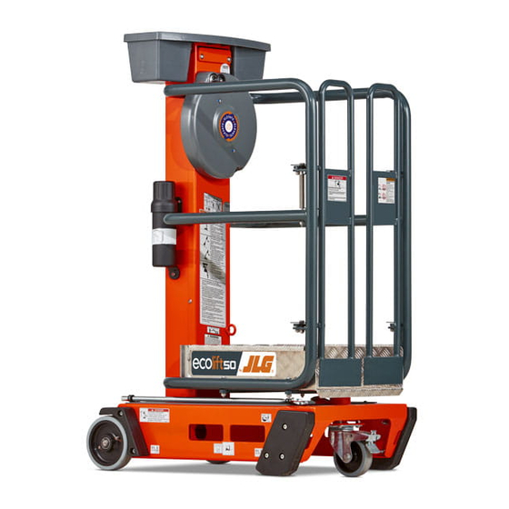
EcoLift 50
Operation and safety manual
JLG EcoLift 50 Operation And Safety Manual
Hide thumbs
1
2
3
4
5
6
7
Table Of Contents
8
9
10
11
12
13
14
15
16
17
18
19
20
21
22
23
24
25
26
27
28
29
30
31
32
33
34
35
36
37
38
39
40
41
42
43
44
45
46
47
48
49
50
51
52
53
54
page
of
54
Go
/
54
Contents
Table of Contents
Bookmarks
Table of Contents
Table of Contents
Section 1 - Safety Precautions
General
Pre-Operation
Operator Training and Knowledge
Workplace Inspection
Machine Inspection
Operation
General
Trip and Fall Hazard
Electrocution Hazard
Tipping Hazards
Minimum Approach Distances (M.A.D.)
Crushing and Collision Hazards
Transporting
Tipping Hazards
Moving, Lifting, and Repositioning
General
Additional Safety Information
Maintenance
Maintenance Hazards
Section 2 - Preparation and Inspection
Personnel Training
Operator Training
Training Supervision
Operator Responsibility
Machine Familiarization
Preparation, Inspection, and Maintenance
Inspection and Maintenance Table
Pre-Start Inspection
Walk-Around Inspection
General
Inspection Diagram (Ecolift 50)
Inspection Diagram (Ecolift 70)
Function Check
Section 3 - Machine Operation
General
Machine Description
Operating Characteristics and Limitations
Placards
Capacities
Stability
Platform Loading
Machine Component Locations
Ecolift 50
Ecolift 70
Machine Operation
Positioning and Leveling Machine
Entering/Exiting the Platform
Elevating/Lowering Platform
Transporting, Lifting, and Tie-Down Procedures
Loading
Storage
Vehicle Transport
Transportation Diagram
Decal Installation (Ecolift 50)
Decal Installation (Ecolift 70)
Section 4 - Emergency Procedures
Incident Notification
Emergency Lowering Operation
Section 5 - General Specifications
Other Publications Available Specific to this Machine
Serial Number Identification
5.1 General Specifications
Machine Specifications
Machine Dimensions
Operating Specifications (Ecolift 50)
Section 6 - Inspection and Repair Log
Advertisement
Quick Links
1
Pre-Operation
2
Operator Training and Knowledge
3
Trip and Fall Hazard
4
Section 3 - Machine Operation
Download this manual
Operation and Safety Manual
Original Instructions - Keep this manual with the machine at all times.
Models
EcoLift 50
SN P900004791 to Present
EcoLift 70
SN P900004841 to Present
®
ANSI
31215860
October 3, 2019 - Rev A
Table of
Contents
Previous
Page
Next
Page
1
2
3
4
5
Advertisement
Table of Contents
Need help?
Do you have a question about the EcoLift 50 and is the answer not in the manual?
Ask a question
Questions and answers
Related Manuals for JLG EcoLift 50
Boom Lifts JLG 510AJ Operation And Safety Manual
(112 pages)
Boom Lifts JLG GRADALL 544D Owner's/Operator's Manual
Material handler (54 pages)
Boom Lifts JLG 544D-10 Operation & Safety Manual
(142 pages)
Boom Lifts JLG 520AJ HC3 Operation & Safety Manual
(128 pages)
Boom Lifts JLG 40H Service And Maintenance Manual
(152 pages)
Boom Lifts JLG G9-43A Operation & Safety Manual
(170 pages)
Boom Lifts JLG 10VP Service And Maintenance Manual
(104 pages)
Boom Lifts JLG 15MVL Series Service Maintenance Manual
(174 pages)
Boom Lifts JLG 80HX Service And Maintenance Manual
(176 pages)
Boom Lifts JLG 600SJ Service And Maintenance Manual
(334 pages)
Boom Lifts JLG 80SL Service Maintenance Manual
(162 pages)
Boom Lifts JLG 1250AJP Troubleshooting Manual
(326 pages)
Boom Lifts JLG 3369LE Operation And Safety Manual
(86 pages)
Boom Lifts JLG T500J Operation And Safety Manual
(132 pages)
Boom Lifts JLG 450A II Series Operation And Safety Manual
(134 pages)
Boom Lifts JLG 740A Service And Maintenance Manual
Articulating (408 pages)
This manual is also suitable for:
Ecolift 70
Table of Contents
Print
Rename the bookmark
Delete bookmark?
Delete from my manuals?
Login
Sign In
OR
Sign in with Facebook
Sign in with Google
Upload manual
Upload from disk
Upload from URL


Need help?
Do you have a question about the EcoLift 50 and is the answer not in the manual?
Questions and answers