
Related Manuals for AMX NXP-PLV


Summary of Contents for AMX NXP-PLV
- Page 1 Operation/Reference Guide NXP-PLV Modero PosiTrack Pilot Camera Controller C a m e r a C o n t r o l l e r s L a s t U p d a t e : 5 / 1 6 / 2 0 0 8...
- Page 2 RMA number. AMX is not liable for any damages caused by its products or for the failure of its products to perform. This includes any lost profits, lost savings, incidental damages, or consequential damages. AMX is not liable for any claim made by a third party or by an AMX Dealer for a third party.
-
Page 3: Fcc Information
FCC Information This device complies with Part 15 of the FCC Rules. Operation is subject to the following two conditions: (1) this device may not cause harmful interference, and (2) this device must accept any interference received; including interference that may cause undesired operation. Federal Communications Commission (FCC) Statement This equipment has been tested and found to comply with the limits for a Class B digital device, pursuant to Part 15 of... -
Page 5: Table Of Contents
Installation ...13 Inside the NXP-PLV... 13 Unpacking the NXP-PLV ... 13 Connecting the NXP-PLV ... 13 Wiring Guidelines for the NXP-PLV ... 14 Preparing captive wires... 14 Wiring a power connection ... 14 Audio/Video Port: Connections and Wiring ... 15 Ethernet/RJ-45 Port: Connections and Wiring ... - Page 6 Step 2: Confirm the Installation of the USB Driver on the PC ... 29 Step 3: Confirm and View the current AMX USB device connections ... 31 Step 4: Use the USB to Configure a Virtual Master (using NetLinx Studio) ... 33 Step 5: Confirm and View the current AMX USB device connections ...
- Page 7 Upgrading the NXP-PLV Firmware via the USB port ... 103 Step 1: Configure the device for a USB Connection Type... 103 Step 2: Prepare NetLinx Studio for communication via the USB port ... 104 Step 3: Confirm and Upgrade the firmware via the USB port ... 105 Upgrading the Modero Firmware via Ethernet (IP Address)...
-
Page 8: Introduction
With the right hand on the soft wrist pad, the operator can also intuitively guide the camera and twist the joystick to zoom the lens in and out. The NXP-PLV supports up to six cameras, and is an ideal controller for AMX’s Ethernet-based PTE-300 PosiTrack Pan/Tilt Head. Refer to the PTE-300 PosiTrack Camera Controller instruction manual for more information on the PTE-300’s features and capabilities. - Page 9 • Level range: 1 - 600 (default level value 0-255, can be set up to 1-65535) • Address port range: 1 - 100 NOTE: the NXP-PLV reserves channels 1-7 and levels 1-11 on Port 1 for hardware functions. These channels/levels are considered reserved by the device and cannot be used for button assignments.
-
Page 10: Product Components
Ethernet and NXA-EVB/Ethernet port. FIG. 3 shows a close-up of the connectors on the back of the NXP-PLV, including the Input/Output jack and the power connector input. - Page 11 Control Focus Control FIG. 4 NXP-PLV - Top view FIG. 5 shows the dimensions for the side of the NXP-PLV, including the arrangement of the speed, iris control, and focus control knobs. 5" (127mm) FIG. 5 NXP-PLV side panel dimensions...
-
Page 12: Nxp-Plv Accessories
The NXA-AVB/ETHERNET Breakout Box (FIG. 6) may be purchased as a separate accessory to the NXP-PLV. This box facilitates the installation and distribution of video, data, and audio to a device located up to 200 feet (60.96 m) from the AVB box. This unit accepts either Composite or S-Video from standard video devices. -
Page 13: Installing The Nxa-Avb/Ethernet
Other AMX Equipment: Installing the NXA-AVB/ETHERNET A 12 VDC-compliant power supply can indirectly provide power to an NXP-PLV by routing power through the NXA-AVB/ETHERNET Breakout Box. FIG. 7 shows a sample wiring configuration using both an indirect or direct power connection for a PosiTrack Pilot controller. -
Page 14: Wiring The Nxa-Avb/Ethernet Connectors And Cables
The inputs and outputs on the breakout box are separated into front and rear connectors. The rear connectors are used to input external signals. The front connectors are used to communicate signals between the NXA-AVB/ETHERNET and a target NXP-PLV. FIG. 8 provides a layout of the wiring connection both into and from the breakout box. -
Page 15: Wiring The Nxa-Avb/Ethernet For Unbalanced Audio
"Live" and "Return" carry the "in-phase" and "out-of-phase" versions of the audio respectively. The pins of the XLR plug/socket are as follows: • X = Ground • L = Live (Hot) • R = Return (Cold) NXP-PLV Modero PosiTrack Pilot Camera Controller Unbalanced IN Left Channel (Jumper IN- to GND) Unbalanced IN... -
Page 16: Modero Table Top Cable (Ca2250-50)
Wiring the rear MIC OUT connector for use with Balanced Audio Modero Table Top Cable (CA2250-50) The NXP-PLV utilizes a standard 10' (3.048 m) Modero cable (CA2250-50) that supports Ethernet, Audio/Video, and Power connections. The cable comes terminated with two RJ45 connectors (Ethernet and Audio/Video) and a single 2-pin captive wire connector for power. - Page 17 White/Orange Orange/White White/Green Blue/White White/Blue Green/White White/Brown Brown/White NXP-PLV Modero PosiTrack Pilot Camera Controller 7" Panel 10" Panel 12" Panel 150’ (45.72 m) 150’ (45.72 m) 49’ (14.94 m) 56’ (17.07 m) 56’ (17.07 m) 25’ (7.62 m) 3 inches...
- Page 18 NONE FIG. 14 Table Top Cable - Specification Elements Each bundle of 4 twisted pairs includes a colored tape indicator for identification. Element #1 Binder Element #2 Connector #3 Jacket 24 AWG STRANDED COPPER NXP-PLV Modero PosiTrack Pilot Camera Controller...
-
Page 19: Footswitch
Footswitch In addition to the speed and iris knobs and the joystick, the NXP-PLV also has an input jack for an optional footswitch (FIG. 3 on page 3) for additional control. The NXP-PLV recognizes three states coming from the I/O jack: press, release, and hold. Any normally open/momentary contact closure footswitch with a 1/4"... -
Page 20: Installation
Connecting the NXP-PLV The NXP-PLV is intended to stand alone on a desktop or tabletop without a bracket or support platform, but it still needs to communicate with its associated cameras in order to function. This may be done by connecting it to a NetLinx master or via a hub or router, but the device still needs to be powered up and connected before it is fully functional. -
Page 21: Wiring Guidelines For The Nxp-Plv
Wiring Guidelines for the NXP-PLV The NXP-PLV uses a 12 VDC-compliant power supply to provide power to the device via the 2-pin 3.5 mm captive wire PWR connector. Use the power requirement information in the Specifications table on page 1 to determine the power draw. -
Page 22: Audio/Video Port: Connections And Wiring
Blue-White 6 --------- 6 Green 7 --------- 7 7 --------- 8 Brown-White 8 --------- 8 Brown NXP-PLV Modero PosiTrack Pilot Camera Controller TIA 568B (male) L - Link LED (green) Lights when the Ethernet cables are connected and terminated correctly. -
Page 23: Usb Port: Connecting And Using Input Devices
RJ-45 wiring diagram USB Port: Connecting and Using Input Devices The NXP-PLV can have up to two USB-capable input devices connected for use on its different firmware and TPD4 panel pages. These input devices can consist of a keyboard or mouse. -
Page 24: Touchscreen Operation
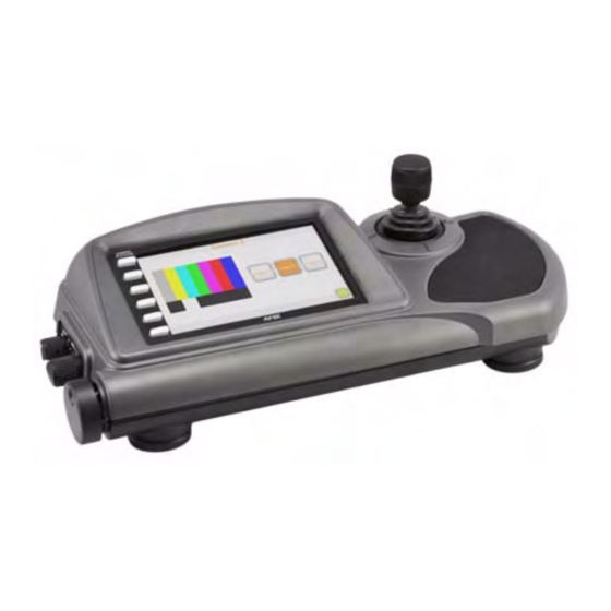
Upgrading NXP-PLV Firmware section on page 103. Presets Page The Presets page is the first screen to appear when the NXP-PLV is first turned on. The view screen displays a live input feed from a selected camera if the camera is already connected to the network (FIG. -
Page 25: Selecting A Preset
Config button on the left disappears, and the joystick and side controls are disabled. Click the button a second time to re-engage the NXP-PLV. Only configured Camera Stations will show a Camera Select feedback button. For example, if only 4 Cameras are configured for on-site control, only the first 4 of the Camera Select feedback buttons will show. -
Page 26: Camera Options Page
The Iris Control button may be switched between Automatic and Manual at any time. Switching to Automatic disables the Iris Control knob on the side of the NXP-PLV. The Preset Recall Speed slidebar controls the speed of the camera’s movement from its current position to a selected preset position. -
Page 27: Camera Limits Page
The Panel Setup button opens the Panel Setup page. See the Panel Setup section on page 27 for more information on setting up a connection for your NXP-PLV. The Camera Limits button opens the Camera Limits page, as detailed on page 20. - Page 28 The Panel Setup button opens the Panel Setup page. See the Panel Setup section on page 27 for more information on setting up a connection for your NXP-PLV. The Camera Options button opens the Camera Options page, as detailed on page 19.
-
Page 29: Calibrating The Nxp-Plv
Calibrating the NXP-PLV This section outlines the steps for calibrating the NXP-PLV. Calibrating the NXP-PLV before its initial use and after completing a firmware download is recommended. The touchscreen is already set up in the factory with specific demo touchscreen pages. The first splash screen that appears indicates the device is receiving power, beginning to load firmware, and preparing to display the default touchscreen pages (FIG. -
Page 30: Calibrating The External Controls
4. Allow the device to calculate the centerpoints on the touchscreen. Do NOT touch the joystick or any of the control knobs while this is being done (FIG. 27). When the device is finished, click Next to proceed to the next page. FIG. 27 Initializing Calibration page NXP-PLV Modero PosiTrack Pilot Camera Controller... - Page 31 6. At the Zoom Calibration page (FIG. 29), rotate the Zoom knob clockwise and then counterclockwise three times, stopping and holding the knob in place for at least two seconds before reversing direction. When done, press the Next button. FIG. 29 Zoom Calibration page NXP-PLV Modero PosiTrack Pilot Camera Controller Touchscreen Operation...
- Page 32 When finished, press the Next button. FIG. 31 Tilt Calibration page 9. When the calibration process is complete, press the enabled Done button at the bottom of the page to return to the Main page. NXP-PLV Modero PosiTrack Pilot Camera Controller...
-
Page 33: Calibrating The Tolerance And Lens Response Settings
The "deadband" in joystick tolerance refers to the amount of movement in which a joystick may be moved before the movement may be acted upon by the NXP-PLV. The deadband tolerance may be lowered for a more delicate response to joystick motions, or raised so that the joystick requires extensive movement before the Positrack Pilot acknowledges the signal. -
Page 34: Configuring Communication
Configuring Communication Configuring Communication Communication between the NXP-PLV and a Master Controller is done using either USB or ETHERNET (DHCP or Static IP). Ethernet communication can be achieved through a direct connection. Before commencing, verify you are using the latest NetLinx Master and device firmware. - Page 35 8. Obtain the System Number and Master IP Address from NetLinx Studio. This information must be specific for the system used with the configured NXP-PLV. 9. Press the Config button on the main page to open the Panel Setup page.
-
Page 36: Configuring And Using Usb With A Virtual Master
Step 2: Confirm the Installation of the USB Driver on the PC The first time each NXP-PLV is connected to the PC, it is detected as a new hardware device and the USBLAN driver becomes associated with it (device specific). Each time thereafter, the device is "recognized"... - Page 37 7. Press the on-screen Reboot button to both save any changes and restart the device. Remember that the device’s connection type must be set to USB prior to rebooting the device and prior to inserting the USB connector. NXP-PLV Modero PosiTrack Pilot Camera Controller Configuring Communication No connection is established until...
-
Page 38: Step 3: Confirm And View The Current Amx Usb Device Connections
FIG. 36 USB driver installation popup window This window notifies you that the NXP-PLV has been detected by the PC as a USB-compliant device, and the PC is installing an appropriate USB driver to establish a proper communication to the device. - Page 39 Within the Device Manager dialog, the AMX USBLAN device appears under Network Adapters (FIG. 37) and has a unique name such as AMX USB LAN LINK #2. The number changes depending on which recognized device is currently connected. FIG. 37 Device Manager dialog showing USB device 3.
-
Page 40: Step 4: Use The Usb To Configure A Virtual Master (Using Netlinx Studio)
To remove the USB driver association from a previously connected NXP-PLV, you must navigate back to the Device Manager, right-click on the device’s USB driver (example: AMX USB LAN LINK #2) and select Uninstall from the context menu and then OK. -
Page 41: Step 5: Confirm And View The Current Amx Usb Device Connections
11. Right-click on the Empty Device Tree/System entry and select Refresh System to re-populate the list. The NXP-PLV will not appear as a device below the virtual system number (in the Online Tree tab) until both the system number used in step 8 for the VNM is entered into the Master Connection section of the System Settings page and the device is restarted. - Page 42 3. Right-click on the System entry (A in FIG. 40) and select Refresh System. This causes a refresh of all project systems, establishes a new connection to the Virtual Master, and populates the System list with devices on your particular system. FIG. 40 Using USB for Virtual Master communication NXP-PLV Modero PosiTrack Pilot Camera Controller...
-
Page 43: Configuring A Wired Ethernet Connection
4. Press the IP Address field to open a Keyboard and enter the Static IP Address (provided by your System Administrator). 5. Press Done after you are finished entering the IP information. 6. Repeat the same process for the Subnet Mask and Gateway fields. NXP-PLV Modero PosiTrack Pilot Camera Controller Configuring Communication... -
Page 44: Step 2: Choose A Master Connection Mode Setting
URL list). In this system, the device acts as a "Server" (in that Clients attach to it) and the Master acts as a "Client". • AUTO is used to instruct the NXP-PLV to search for a Master that uses the same System Number (assigned within the Master Connection section) and resides on the same Subnet as itself. In this case, the Master has its UDP feature enabled. -
Page 45: Master Connection Section - Virtual Master Communication Over Ethernet
1. Verify the device has been configured to communicate through an Ethernet cable connected from the panel to a valid Ethernet Hub. 2. Launch NetLinx Studio 2.x (default location is Start > Programs > AMX Control Disc > NetLinx Studio 2 > NetLinx Studio 2). - Page 46 11. Right-click on the Empty Device Tree/System entry and select Refresh System to re-populate the list. 12. Power-up your device and proceed to the Setup page. IP Addresses of computer (also obtained by using the Start > Run > cmd command) NXP-PLV Modero PosiTrack Pilot Camera Controller...
-
Page 47: Master Connection Section - Netlinx Master Ethernet Ip Address - Url Mode
By selecting URL, the System Number field becomes read-only (grey) because the panel pulls this value directly from the communicating target Master (virtual or not). A Virtual Master system value can be set within the active AMX software applications such as NetLinx Studio, TPD4, or IREdit. -
Page 48: Master Connection Section - Netlinx Master Ethernet Ip Address - Listen Mode
Master Connection section - NetLinx Master Ethernet IP Address - Listen Mode In this mode, you must add the NXP-PLV IP Address into the URL List of the Master (using NetLinx Studio). This mode sets the device to "listen" for broadcasts from the Master (using the device IP from its URL list). -
Page 49: Master Connection Section - Netlinx Master Ethernet Ip Address - Auto Mode
Master Connection section - NetLinx Master Ethernet IP Address - Auto Mode In this mode, enter the System Number of the NetLinx Master. This mode instructs the NXP-PLV to search for a Master that uses the same System Number (assigned within the Master Connection section) and resides on the same Subnet as itself. -
Page 50: Using G4 Web Control To Interact With A Nxp-Plv
Using G4 Web Control to Interact with a NXP-PLV The G4 Web Control feature allows you to use a PC to interact with an NXP-PLV via the web. This feature works in tandem with the new browser-capable NetLinx Security firmware update (build 300 or higher). - Page 51 19. Press the on-screen Reboot button to save any changes and restart the device. Verify your NetLinx Master’s IP Address and System Number have been properly entered into the Master Connection section of the System Settings page. NXP-PLV Modero PosiTrack Pilot Camera Controller Configuring Communication...
-
Page 52: Using Your Netlinx Master To Control The Nxp-Plv
If the Master has been previously configured for secured communication, click OK to accept the AMX SSL certificate (if SSL is enabled) and then enter a valid username and password into the fields within the Login dialog. 4. Click OK to enter the information and proceed to the Master’s Manage WebControl Connections window. - Page 53 10. Enter the Web Control session password into the Session Password field (FIG. 48). This password was previously entered into the Web Control Password field within the G4 Web Control page on the device. NXP-PLV Modero PosiTrack Pilot Camera Controller Configuring Communication IP Address of device...
- Page 54 A small circle appears within the on-screen G4 panel page and corresponds to the location of the mouse cursor. A left-mouse click on the computer-displayed panel page equates to an actual touch on the target device page. NXP-PLV Modero PosiTrack Pilot Camera Controller...
- Page 55 Configuring Communication NXP-PLV Modero PosiTrack Pilot Camera Controller...
-
Page 56: Programming
Designing Touch Panel Pages You may create touch panel pages for your NXP-PLV by using TPDesign4. Refer to the TPDesign Touch Panel Program instruction manual for more information. Designing touch panel pages for the NXP-PLV requires TPDesign4 v2.8 or higher. -
Page 57: Reserved Level Descriptions
- Positional Disabled by default. Level 4 Focus - Positional, Near knob (largest) Enabled by default. NXP-PLV Modero PosiTrack Pilot Camera Controller Description JOYSTICK - LEFT / RIGHT JOYSTICK - UP/DOWN JOYSTICK - TWIST - POSITIONAL KNOB - NEAR - POSITIONAL... - Page 58 When looking at the left side of the device at the iris knob, the counterclockwise rotational speed is propor- tional to the positive offset from level center (127). The clockwise rotational speed is proportional to the negative offset from level centers. NXP-PLV Modero PosiTrack Pilot Camera Controller...
-
Page 59: Reserved Channel Descriptions
Joystick is in the east quadrant. Joystick is in the west quadrant. Joystick is in the north quadrant. Joystick is in the south quadrant. Joystick is twisted clockwise. Joystick is twisted counterclockwise. External footswitch port closed. NXP-PLV Modero PosiTrack Pilot Camera Controller Programming... -
Page 60: Page Commands
"'@PDR-<popup page name>;<reset flag>'" popup page name = 1 - 50 ASCII characters. Name of the page the popup is displayed reset flag = 1 = Enable reset flag 0 = Disable reset flag SEND_COMMAND Panel,"'@PDR-Popup1;1'" NXP-PLV Modero PosiTrack Pilot Camera Controller... - Page 61 Variable: Example: Close all popups on Page1. NXP-PLV Modero PosiTrack Pilot Camera Controller "'@PHE-<popup page name>;<hide effect name>'" popup page name = 1 - 50 ASCII characters. Name of the page the popup is displayed hide effect name = Refers to the popup effect names being used.
- Page 62 = 1 - 50 ASCII characters. Name of the page the popup is displayed On. SEND_COMMAND Panel,"'@PPG-Popup1;Main'" SEND_COMMAND Panel,"'@PPG-Popup1'" "'@PPK-<popup page name>'" popup page name = 1 - 50 ASCII characters. Name of the popup page. SEND_COMMAND Panel,"'@PPK-Popup1'" NXP-PLV Modero PosiTrack Pilot Camera Controller...
-
Page 63: Programming Numbers
Dark Lime Very Dark Lime Very Light Green Light Green Green Medium Green Dark Green Very Dark Green Very Light Mint Light Mint Mint Medium Mint Dark Mint Very Dark Mint NXP-PLV Modero PosiTrack Pilot Camera Controller Green Blue Programming... - Page 64 Very Light Magenta Light Magenta Magenta Medium Magenta Dark Magenta Very Dark Magenta Very Light Pink Light Pink Pink Medium Pink Dark Pink Very Dark Pink White Grey1 Grey3 Grey5 Grey7 Grey9 Grey4 Grey6 Green Blue NXP-PLV Modero PosiTrack Pilot Camera Controller...
-
Page 65: Font Styles And Id Numbers
Courier New Courier New Courier New Courier New Courier New Courier New Courier New AMX Bold AMX Bold AMX Bold NXP-PLV Modero PosiTrack Pilot Camera Controller Green Size Font ID # Font type Arial Arial Arial Arial Arial Arial Arial... -
Page 66: Font Styles And Id Numbers
Arial Arial Arial Arial Arial Bold Arial Bold 32 - Variable Fonts start at 32. Border styles 10-11 Picture frame Double line Bevel-S Bevel-M 22-23 Circle 15 24-27 Neon inactive-S 40-41 Diamond 55 NXP-PLV Modero PosiTrack Pilot Camera Controller Size... - Page 67 Double Bevel -L Double Bevel -M Double Bevel -S Double Line Fuzzy Glow-L Glow-S Help Down NXP-PLV Modero PosiTrack Pilot Camera Controller Border styles Circle 155 Circle 165 Circle 175 Circle 185 Circle 195 Cursor Bottom Cursor Bottom with Hole...
- Page 68 Menu Right Rounded 15 Menu Right Rounded 25 Menu Right Rounded 35 Menu Right Rounded 45 Menu Right Rounded 55 Menu Right Rounded 65 Menu Right Rounded 75 Menu Right Rounded 85 Menu Right Rounded 95 NXP-PLV Modero PosiTrack Pilot Camera Controller...
-
Page 69: Button Commands
Variable: Example: Appends the text 'Enter City' to the button’s OFF state. NXP-PLV Modero PosiTrack Pilot Camera Controller "'^ANI-<vt addr range>,<start state>,<end state>,<time>'" variable text address range = 1 - 4000. start state = Beginning of button state (0= current state). - Page 70 1 = Off state and 2 = On state). color value = Refer to theRGB Values for all 88 Basic Colors table on page 56 for more information. SEND_COMMAND Panel,"'^BCF-500.504&510.515,1,12'" SEND_COMMAND Panel,"'^BCF-500.504&510.515,1,Yellow'" SEND_COMMAND Panel,"'^BCF-500.504&510.515,1,#F4EC0A63''" SEND_COMMAND Panel,"'^BCF-500.504&510.515,1,#F4EC0A'" NXP-PLV Modero PosiTrack Pilot Camera Controller...
- Page 71 Variable: Example: Sets the Feedback type of the button to 'Momentary'. NXP-PLV Modero PosiTrack Pilot Camera Controller "'^BCT-<vt addr range>,<button states range>,<color value>'" variable text address range = 1 - 4000. button states range = 1 - 256 for multi-state buttons (0 = All states, for General buttons 1 = Off state and 2 = On state).
- Page 72 = 1 - 256 for multi-state buttons (0 = All states, for General buttons 1 = Off state and 2 = On state). number of lines = 0 - 240. SEND_COMMAND Panel,"'^BLN-500,55'" NXP-PLV Modero PosiTrack Pilot Camera Controller...
- Page 73 315 onto the OFF state border, font, Text, bitmap, icon, fill color and text color of the button with a variable text address of 150. NXP-PLV Modero PosiTrack Pilot Camera Controller "'^BMC-<vt addr range>,<button states range>,<source port>,<source address>,<source state>,<codes>'"...
- Page 74 BUT the 0 (zero) is absolute and followed by ’,<left>,<top>’ ’%JI<alignment of icon 0-9>’ = As shown the above telephone keypad alignment chart, BUT the 0 (zero) is absolute and followed by ’,<left>,<top>’ NXP-PLV Modero PosiTrack Pilot Camera Controller...
- Page 75 Sets the button OFF state as well as the Border, Fill Color, Border Color, Text Color, and Bitmap. NXP-PLV Modero PosiTrack Pilot Camera Controller For some of these commands and values, refer to the RGB Values for all 88 Basic Colors table on page 56.
- Page 76 1 = Off state and 2 = On state). name of bitmap/picture = 1 - 50 ASCII characters. SEND_COMMAND Panel,"'^BMP-500.504&510.515,1,bitmap.png'" "'^BNC-<vt addr range>,<command value>'" variable text address range = 1 - 4000. command value = (0= clear, 1= clear all). SEND_COMMAND Panel,"'^BNC-973,0'" NXP-PLV Modero PosiTrack Pilot Camera Controller...
- Page 77 Example 2: Both examples set the opacity of the buttons with the variable text range of 500-504 and 510-515 to 200. NXP-PLV Modero PosiTrack Pilot Camera Controller "'^BNN-<vt addr range>,<network name>'" variable text address range = 1 - 4000. network name = Use a valid IP Address.
- Page 78 Sets the border by number (#10) to those buttons with the variable text range of 500-504 & 510-515. Sets the border by name (AMX Elite) to those buttons with the variable text range of 500-504 & 510-515. The border style is available through the TPDesign4 border-style drop-down list. Refer to the TPD4 Border Styles by Name table on page 60 for more information.
- Page 79 Variable: Example: Assigns the sound 'music.wav' to the button Off/On states. NXP-PLV Modero PosiTrack Pilot Camera Controller "'^BRD-<vt addr range>,<button states range>,<border name>'" variable text address range = 1 - 4000. button states range = 1 - 256 for multi-state buttons (0 = All states;...
- Page 80 = 1 - 256 for multi-state buttons (0 = All states, for General buttons 1 = Off state and 2 = On state). word wrap = (0=Off and 1=On). Default is Off. SEND_COMMAND Panel,"'^BWW-500,1,1'" NXP-PLV Modero PosiTrack Pilot Camera Controller...
- Page 81 NOTE: The Font ID is generated by TPD4 and is located in TPD4 through the Main menu. Panel > Generate Programmer’s Report > Text Only Format > Readme.txt NXP-PLV Modero PosiTrack Pilot Camera Controller "'^CPF-<vt addr range>'" variable text address range = 1 - 4000.
- Page 82 = 1 - 65535 (bargraph lower limit range). SEND_COMMAND Panel,"'^GLL-500,150'" "'^GRD-<vt addr range>,<bargraph ramp down time>'" variable text address range = 1 - 4000. bargraph ramp down time = In 1/10th of a second intervals. SEND_COMMAND Panel,"'^GRD-500,200'" NXP-PLV Modero PosiTrack Pilot Camera Controller...
- Page 83 Variable: Example: Changes the bargraph slider name or the Joystick cursor name to ’Ball’. NXP-PLV Modero PosiTrack Pilot Camera Controller "'^GRU-<vt addr range>,<bargraph ramp up time>'" variable text address range = 1 - 4000. bargraph ramp up time = In 1/10th of a second intervals.
- Page 84 = 1 - 256 for multi-state buttons (0 = All states, for General buttons 1 = Off state and 2 = On state). new icon alignment = Value of 1 - 9 corresponds to the following locations: Zero can be used for an absolute position SEND_COMMAND Panel,"'^JSI-500.504&510.515,1&2,1'" NXP-PLV Modero PosiTrack Pilot Camera Controller...
- Page 85 Example: Hides buttons with variable text address range 500-504 & 510-515. NXP-PLV Modero PosiTrack Pilot Camera Controller "'^JST-<vt addr range>,<button states range>,<new text alignment>'" variable text address range = 1 - 4000. button states range = 1 - 256 for multi-state buttons (0 = All states, for General buttons 1 = Off state and 2 = On state).
- Page 86 = 1 - 256 for multi-state buttons (0 = All states; for General buttons, 1 = Off state and 2 = On state). new text = 1 - 50 ASCII characters. SEND_COMMAND Panel,"'^TXT-500.504&510.515,1&2,Test Only'" NXP-PLV Modero PosiTrack Pilot Camera Controller...
- Page 87 Note: Unicode is always represented in a HEX value. TPD4 generates (through the Text Enter Box dialog) unicode HEX values. Refer to the TPDesign4 Instruction Manual for more information. NXP-PLV Modero PosiTrack Pilot Camera Controller "'^UNI-<vt addr range>,<button states range>,<unicode text>'" variable text address range = 1 - 4000.
-
Page 88: Text Effect Names
• Hard Drop Shadow 4 with outline • Hard Drop Shadow 5 with outline • Hard Drop Shadow 6 with outline • Hard Drop Shadow 7 with outline • Hard Drop Shadow 8 with outline NXP-PLV Modero PosiTrack Pilot Camera Controller... -
Page 89: Button Query Commands
Custom Event Fields Field Uint Flag slong value1 slong value2 slong value3 string text text length (string encode) NXP-PLV Modero PosiTrack Pilot Camera Controller // Text // Bitmap // Icon // Text Justification // Bitmap Justification // Icon Justification // Font... - Page 90 Text length - Color name length (should be 9) SEND COMMAND Panel,"'?BCB-529,1'" ButtonGet Id = 529 Type = 1011 Flag = 0 VALUE1 = 1 VALUE2 = 9 VALUE3 = 0 TEXT = #222222FF TEXT LENGTH = 9 NXP-PLV Modero PosiTrack Pilot Camera Controller...
- Page 91 Example: Gets the button 'OFF state' text color information. The result sent to Master would be: NXP-PLV Modero PosiTrack Pilot Camera Controller "'?BCF-<vt addr range>,<button states range>'" variable text address range = 1 - 4000. button states range = 1 - 256 for multi-state buttons (0 = All states;...
- Page 92 Text - Blank Text length - Zero SEND COMMAND Panel,"'?BOP-529,1'" ButtonGet Id = 529 Type = 1015 Flag = 0 VALUE1 = 1 VALUE2 = 200 VALUE3 = 0 TEXT = TEXT LENGTH = 0 NXP-PLV Modero PosiTrack Pilot Camera Controller...
- Page 93 Example: Gets the button 'OFF state' word wrap flag status information. The result sent to the Master would be: NXP-PLV Modero PosiTrack Pilot Camera Controller "'?BRD-<vt addr range>,<button states range>'" variable text address range = 1 - 4000. button states range = 1 - 256 for multi-state buttons (0 = All states;...
- Page 94 Text - Blank Text length - Zero SEND COMMAND Panel,"'?ICO-529,1&2'" ButtonGet Id = 529 Type = 1003 Flag = 0 VALUE1 = 2 VALUE2 = 12 VALUE3 = 0 TEXT = TEXT LENGTH = 0 NXP-PLV Modero PosiTrack Pilot Camera Controller...
- Page 95 Example: Gets the button 'OFF state' icon justification information. The result sent to the Master would be: NXP-PLV Modero PosiTrack Pilot Camera Controller "'?JSB-<vt addr range>,<button states range>'" variable text address range = 1 - 4000. button states range = 1 - 256 for multi-state buttons (0 = All states;...
- Page 96 ButtonGet Id = 529 Type = 1004 Flag = 0 VALUE1 = 1 VALUE2 = 1 VALUE3 = 0 TEXT = TEXT LENGTH = 0 "'?PLL'" SEND COMMAND Panel,”'?PLL'” PL_ENABLED=<comma-delimited list of enabled levels> NXP-PLV Modero PosiTrack Pilot Camera Controller...
- Page 97 Example: Gets the button 'OFF state' text effect name information. The result sent to the Master would be: NXP-PLV Modero PosiTrack Pilot Camera Controller "'?TEC-<vt addr range>,<button states range>'" variable text address range = 1 - 4000. button states range = 1 - 256 for multi-state buttons (0 = All states;...
- Page 98 Text length - Button text length SEND COMMAND Panel,"'?TXT-529,1'" ButtonGet Id = 529 Type = 1001 Flag = 0 VALUE1 = 1 VALUE2 = 14 VALUE3 = 1 TEXT = This is a test TEXT LENGTH = 14 NXP-PLV Modero PosiTrack Pilot Camera Controller...
-
Page 99: Panel Runtime Operations
@AKB, @AKP, @PKP, @EKP, or @TKP commands. Remove the Keyboard/ Syntax: Keypad. Example: Removes the Keyboard/Keypad. NXP-PLV Modero PosiTrack Pilot Camera Controller "'ABEEP'" SEND COMMAND Panel,"'ABEEP'" "'ADBEEP'" SEND COMMAND Panel,"'ADBEEP'" "'@AKB-<initial text>;<prompt text>'" initial text = 1 - 50 ASCII characters. - Page 100 "'@AKR'" SEND COMMAND Panel,"'@AKR'" "'BEEP'" SEND COMMAND Panel,"'BEEP'" "'BRIT-<brightness level>'" brightness level = 0 - 100. SEND COMMAND Panel,"'BRIT-50'" "'@BRT-<brightness level>'" brightness level = 0 - 100. SEND COMMAND Panel,"'@BRT-70'" "'DBEEP'" SEND COMMAND Panel,"'DBEEP'" NXP-PLV Modero PosiTrack Pilot Camera Controller...
- Page 101 Example: mode. Forces the panel into screen saver mode. NXP-PLV Modero PosiTrack Pilot Camera Controller "'@EKP-<initial text>;<prompt text>'" initial text = 1 - 50 ASCII characters. prompt text = 1 - 50 ASCII characters. SEND COMMAND Panel,"'@EKP-33333333;Enter Password'"...
- Page 102 = 1 - 50 ASCII characters. prompt text = 1 - 50 ASCII characters. SEND COMMAND Panel,"'@TKP-999.222.1211;Enter Phone Number'" "'TPAGEON'" SEND COMMAND Panel,"'TPAGEON'" "'TPAGEOFF'" SEND COMMAND Panel,"'TPAGEOFF'" "'@VKB'" SEND COMMAND Panel,"'@VKB'" "'WAKE'" SEND COMMAND Panel,"'WAKE'" NXP-PLV Modero PosiTrack Pilot Camera Controller...
-
Page 103: Input Commands
= 0 - 24,000 Example: SEND COMMAND Panel,"'PANTOL=500'" Syntax: ^PLD Disables specific PosiTrack Levels Example: NXP-PLV Modero PosiTrack Pilot Camera Controller "'^CAL'" SEND COMMAND Panel,"'^CAL'" "'^JOYCAL'" SEND_COMMAND PANEL,"'^JOYCAL'" "'^KPS-<pass data>'" pass data: <blank/empty> = Disables the keyboard. 0 = Pass data to G4 application (default). This can be used with VPC or text areas. - Page 104 = 0 - 24,000 Example: SEND COMMAND Panel,"'ZOOMTOL=500'" "'^PLE=<comma-delimited list of levels to enable>"' SEND COMMAND Panel,”'^PLE=1,3,4,5,9'” "'^PLR=<level>,<res>'" SEND COMMAND Panel,”'^PLR=1,8'" "'^VKS-<string>'" string = Only 1 string per command/only one stroke per command. SEND COMMAND Panel,"'^VKS-'8" NXP-PLV Modero PosiTrack Pilot Camera Controller...
-
Page 105: Embedded Codes
Embedded codes The following is a list of compatible embedded codes: Embedded Codes Decimal numbers Hexidecimal values NXP-PLV Modero PosiTrack Pilot Camera Controller Virtual keystroke ($08) Backspace ($0D) Enter ($1B) ($80) CTRL key down ($81) ALT key down ($82) Shift key down... -
Page 106: Panel Setup Commands
"'^PWD-<password level>,<page flip password>'" password level = 1 - 4. page flip password = 1 - 50 ASCII characters. SEND COMMAND Panel,"'^PWD-1,Main'" "'^VOL-<volume level>'" volume level = 0 - 100. 100 is maximum volume setting. SEND_COMMAND Panel,"'^VOL-50'" NXP-PLV Modero PosiTrack Pilot Camera Controller... -
Page 107: Dynamic Image Commands
Example: Sets the refresh rate to 5 seconds for the given resource (’Sports_Image’). NXP-PLV Modero PosiTrack Pilot Camera Controller "'^BBR-<vt addr range>,<button states range>,<resource name>'" variable text address range = 1 - 4000. button states range = 1 - 256 for multi-state buttons (0 = All states, for General buttons 1 = Off state and 2 = On state). - Page 108 Example: Adds a new resource. The resource name is ’New Image’, %P (protocol) is an HTTP, %H (host name) is AMX.COM, %A (file path) is Lab/Test file, and %F (file name) is test.jpg. "'^RAF-<resource name>,<data>'" resource name = 1 - 50 ASCII characters.
- Page 109 Programming NXP-PLV Modero PosiTrack Pilot Camera Controller...
-
Page 110: Upgrading Nxp-Plv Firmware
Set up and configure your NetLinx Master. Refer to the particular NetLinx Master Instruction Manual for your master for detailed setup procedures. Calibrate and prepare the communication pages on the NXP-PLV for use. Refer to the Panel Setup section on page 27. -
Page 111: Step 2: Prepare Netlinx Studio For Communication Via The Usb Port
8. Navigate back to the System Settings page. Step 2: Prepare NetLinx Studio for communication via the USB port 1. Launch NetLinx Studio 2.x (default location is Start > Programs > AMX Control Disc > NetLinx Studio 2 > NetLinx Studio 2). -
Page 112: Step 3: Confirm And Upgrade The Firmware Via The Usb Port
NetLinx Workspace window (showing the panel connection via a Virtual NetLinx Master) Showing the Virtual Master firmware version and device number Showing NetLinx Studio version number Showing the current firmware version and device number NXP-PLV Modero PosiTrack Pilot Camera Controller... - Page 113 5. If the panel firmware being used is not current, download the latest Kit file by first logging in to www.amx.com and then navigate to Tech Center > Firmware Files. Locate your device from within the Modero section of the web page.
-
Page 114: Upgrading The Modero Firmware Via Ethernet (Ip Address)
NetLinx Master instruction manual to use an address. Note the IP Address and Gateway information. 2. Launch NetLinx Studio 2.x (default location is Start > Programs > AMX Control Disc > NetLinx Studio 2 > NetLinx Studio 2). -
Page 115: Step 2: Prepare The Panel For Communication Via An Ip
By selecting URL, the System Number field becomes read-only (grey) because the device pulls this value directly from the communicating target Master (virtual or not). A Virtual Master system value can be set within the active AMX software applications such as: NetLinx Studio, TPD4, or IREdit. -
Page 116: Step 3: Verify And Upgrade The Panel Firmware Via An Ip
4. If the firmware being used is not current, download the latest Kit file by first logging in to www.amx.com and then navigate to Tech Center > Firmware Files and locate your device from within the Modero section of the Web page. - Page 117 Master, and populates the System list with devices on your particular system. 13. Confirm the panel has been properly updated to the correct firmware version. NXP-PLV Modero PosiTrack Pilot Camera Controller Upgrading NXP-PLV Firmware Showing the NetLinx Master...
-
Page 118: Troubleshooting
System Tray. • Double click on the icon to bring up the list of USB devices (you should see the "AMX USB LAN LINK" device in the list). • If the Install Driver dialog doesn't appear automatically, select the Properties button and then the Update Driver button. - Page 119 "USB Connecting" is displayed when the device is trying to establish USB communication with the PC (either within the NetLinx Studio or TPDesign4 applications). • Remove the USB connector from the device and close any AMX applications. • Reboot the device.
- Page 120 "Mid Range Fallout" problem. This is due to the graphics controller settings in the firmware. • Update to the latest v2.XX.XX firmware. Visit the www.amx.com > Tech Center > Downloadable Files > Firmware Files > Modero panels and download the KIT file to your computer.
- Page 121 "graphics hierarchy" errors, etc., indicating problems with the Compact Flash. • Device will not boot, or gets stuck on "AMX" splash screen. • Other problems also started after downloading to a new device or a device with a TPD4 file that takes up a considerable amount of the available Compact Flash.
-
Page 122: Appendix A
Appendix A Appendix A Text Formatting Codes for Bargraphs/Joysticks Text formatting codes for bargraphs provide a mechanism to allow a portion of a bargraph’s text to be dynamically provided information about the current status of the level (multistate and traditional). These codes would be entered into the text field along with any other text. -
Page 123: Text Area Input Masking
Text Area Input Masking Text Area Input Masking can be used to limit the allowed/correct characters that are entered into a text area. For example, in working with a zip code, a user could limit the entry to a max length of only 5 characters but, with input masking, you could limit them to 5 mandatory numerical digits and 4 optional numerical digits. -
Page 124: Input Mask Ranges
Appendix A Refer to the following Send Commands for more detailed information: • ^BIM page 65). • ^BMF ^BMF section on page 67). Input mask ranges These ranges allow a user to specify the minimum and maximum numeric value for a field. Only one range is allowed per field. -
Page 125: Input Mask Output Examples
A keyboard entry using normal text entry is straightforward. However, once an input mask is applied, the behavior of the keyboard needs to change to accommodate the input mask's requirement. When working with masks, any literal characters in the mask will be "skipped" by any cursor movement, including cursor keys, backspace, and delete. -
Page 126: Url Resources
(HyperText Transport Protocol) and that the information resides on a host machine named www.amx.com. The image on that host machine is given an assignment (by the program) name of company-info-home.asp (Active Server Page). - Page 127 Appendix A 7" Modero Widescreen Touch Panels...
- Page 129 It’s Your World - Take Control™ 3000 RESEARCH DRIVE, RICHARDSON, TX 75082 USA • 800.222.0193 • 469.624.8000 • 469-624-7153 fax • 800.932.6993 technical support • www.amx.com...
Need help?
Do you have a question about the NXP-PLV and is the answer not in the manual?
Questions and answers