Table of Contents

Subscribe to Our Youtube Channel
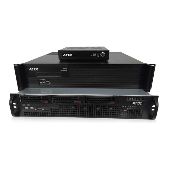
Related Manuals for AMX SC-N8012


Summary of Contents for AMX SC-N8012
- Page 1 U S E R M A N UA L N - S E R I E S C O N T R O L L E R S N - C O M M A N D 2 . 0 C O N T R O L A P P L I C AT I O N S SVS I SYSTE M CO N FI G UR ATIO N M A N AGE M EN T SC-N8001 (5 USERS/ 50 DEVICES), SC-N80 02 (UNLIMITED), SC- N8012 (E NTERPRISE)
- Page 2 COPYRIGHT NOTICE AMX© 2018, all rights reserved. No part of this publication may be reproduced, stored in a retrieval system, or transmitted, in any form or by any means, electronic, mechanical, photocopying, recording, or otherwise, without the prior written permission of AMX. Copyright protection claimed...
- Page 3 Anyone performing field maintenance on AMX equipment should use an appropriate ESD field service kit complete with at least a dissipative work mat with a ground cord and a UL listed adjustable wrist strap with another ground cord WARNING: Do Not Open! Risk of Electrical Shock.
-
Page 4: Table Of Contents
Table of Contents Table of Contents Chapter 1: Introducing Your New N8000 .................... 6 Product Overview..............................6 Hardware Overview..............................7 N8001 N-Command Controller ........................7 N8002 N-Command Controller ........................7 N8012 N-Command Controller ........................8 Chapter 2: Installing and Configuring the N8000 ................9 Preparing for Install .............................. - Page 5 Table of Contents Appendix A: Panel Builder Tutorial ....................43 Beginning a Panel Builder Project........................43 Top Ribbon Option Descriptions ........................45 Project Pane Option Descriptions ........................47 Item Properties Tab............................. 47 Panel Tab..............................48 Project Tab ..............................49 Assets Tab..............................49 Tools Pane Option Descriptions .........................
-
Page 6: Chapter 1: Introducing Your New N8000
SC-N8001 offers AV switching for 5 users and 50 devices, while the SC-N8002/SC-N8012 allow unlimited users and devices. N-Command Control Appliances also include a simplified ASCII interface for third-party control via TCP/IP. Basic features are listed below. See... -
Page 7: Hardware Overview
Chapter 1: Introducing Your New N8000 Hardware Overview N8001 N-Command Controller Refer to Figure 1 as well as the Front and Rear Panel Descriptions table on page 8 for hardware details on the N8001 N-Command Controller. Power On/Off Switch Power Input RJ-45 auto-sensing gigabit ethernet port N8001 Front and Rear Panel FIG. -
Page 8: N8012 N-Command Controller
Chapter 1: Introducing Your New N8000 N8012 N-Command Controller The N8012 is built from a standard computer, but not all buttons, LEDs, and connectors are enabled. Refer to Figure 3 as well as the Front and Rear Panel Descriptions table on page 8 for hardware details on the N8012 N-Command Controller. -
Page 9: Chapter 2: Installing And Configuring The N8000
The SC-N8001 only requires the included power adapter and a single network connection (to the LAN port) to allow up to five users to simultaneously configure, set-up, and control as many as 50 Networked AV devices. The SC-N8002 and SC-N8012 require a network connection to the Eth 1 port in order to control unlimited devices with unlimited users. -
Page 10: Establishing Communication With The N8000
Chapter 2: Installing and Configuring the N8000 Step 2: Establishing Communication with the N8000 Each controller ships with dual IP addresses (192.168.1.99 with a netmask of 255.255.255.0 and 169.254.10.99 with a netmask of 255.255.0.0). • For the single Ethernet port of the N8001: The single Eth1 port is assigned both IP addresses. -
Page 11: Chapter 3: Configuration Options
Chapter 3: Configuration Options Chapter 3: Configuration Options This chapter defines N-Command’s configuration options. For ease of navigation, it is organized to reflect the graphical user interface (GUI). From any main page in the GUI, you can access all other main sections by clicking the links in the top navigation bar. Figure 6 shows the navigation bar and provides hot links to the sections of this chapter which describe each main section. -
Page 12: Video Matrix Page
Chapter 3: Configuration Options Video Matrix Page Click View > Video Matrix to access the page shown in Figure 8. This page displays all discovered devices on your network. Encoders are listed horizontally across the top of the page while Decoders are listed vertically down the left side. Clicking a unit’s name takes you to the configuration pages for that device. -
Page 13: Audio Matrix Page
Chapter 3: Configuration Options Video Matrix Page Option Descriptions (Cont.) TABLE 3 Option Description Notes Hide NVR checkbox Enable to hide all discovered N6123 Network Video Recorders on this network. Script Builder Page on page 21 Launch Script Choose a script to launch from the drop-down menu. for more drop-down Scripts are created using the Script Builder. - Page 14 Chapter 3: Configuration Options Audio Matrix Page Option Descriptions TABLE 4 Option Description Notes Click the circle in the Encoder’s ALL cell to connect all This triggers N-Command to send a command to all compatible streams to that Encoder. compatible Decoders to switch to that one Encoder. Hide inactive checkbox Enable to hide any discovered units that are currently not communicating (off-line).
-
Page 15: Usb Matrix Page
Chapter 3: Configuration Options USB Matrix Page Click View> USB Matrix to access the page shown in Figure 10. This page displays all discovered devices on your network which feature USB support. Encoders are listed horizontally across the top of the page while Decoders are listed vertically down the left side. -
Page 16: Nvr Controls Page
Chapter 3: Configuration Options NVR Controls Page Click View > NVR Controls to access the page shown in Figure 11. Options are described in Table NVR Controls Page FIG. 11 NVR Controls Option Descriptions TABLE 6 Option Description Notes NVR drop-down Select an NVR from the list of discovered NVRs on your network. - Page 17 Chapter 3: Configuration Options Recording Settings The section of the NVR Controls page shown in Figure 12 is displayed when you click the Recording link. Options are described in Table Recording Settings FIG. 12 NVR Controls Page: Recording Settings TABLE 7 Option Description Notes...
- Page 18 Chapter 3: Configuration Options NVR Copy Settings The section of the NVR Controls page shown in Figure 13 is displayed when you click the NVR Copy link. Options are described in Table NVR Copy Settings FIG. 13 NVR Controls Page: NVR Copy Settings TABLE 8 Option Description...
-
Page 19: Panel Viewer Page
Chapter 3: Configuration Options Panel Viewer Page Click View > Panel Viewer link to access the page shown in Figure 15. Options are described in Table Panel Viewer Page FIG. 15 Panel Viewer Option Descriptions TABLE 10 Option Description Notes Panels list Lists any panels that are saved on N-Command (through Panel Builder). -
Page 20: Build Options
Chapter 3: Configuration Options Build Options Click the Build link at the top of any of the main web pages to access the options shown in Figure 16. Refer to the following sections for detailed descriptions: Script Builder Page on page 21 ... -
Page 21: Script Builder Page
Chapter 3: Configuration Options Script Builder Page Click Build > Script Builder to access the page shown in Figure 17. Scripts are programs you write to use over and over again. For example, you could create scripts that shut all equipment down for the evening, putting your Encoders and Decoders in lower power mode, turning off all TVs and lights, etc. - Page 22 Chapter 3: Configuration Options Script Builder Option Descriptions (Cont.) TABLE 11 Option Description Notes Import button Click to import a script. Export button Click to export a script. Scripts export as JSON (a standard human-readable serialized format). Tools icon Here you can select if the scripts are created with the IP address, the MAC address, or the name of the unit.
-
Page 23: Task Builder Page
Chapter 3: Configuration Options Task Builder Page Click Build > Task Builder to access the page shown in Figure 18. After you have created scripts (as discussed previously in the Script Builder Page on page 21) use Task Builder to schedule when those scripts will be executed. Click on a day to schedule a task. Options are described in Table Task Builder Page... -
Page 24: Wall Builder Page
Chapter 3: Configuration Options Wall Builder Page Click Build > Wall Builder to access the page shown in Figure 19. Refer to Appendix B: Wall Builder Tutorial on page 52 for details on this feature. Wall Builder Page FIG. 19 N-Command User Manual... -
Page 25: Third Party Page
Chapter 3: Configuration Options Third Party Page Click Build > Third Party to access the page shown in Figure 20. Options are described in Table 13. Here you can add information about your third party system. This information then populates within Panel Builder and Script Builder. For example, if you know you are going to be controlling a certain brand of television, you can enter the model information here and then re-use that information in Panel Builder and Script Builder. -
Page 26: Panel Builder Page
Chapter 3: Configuration Options Panel Builder Page Click Build > Panel Builder to access the page shown in Figure 21. Panel Builder is a GUI application that allows you to create custom panels to be used as a standalone control option or as an extension to a third-party control system. Using Panel Builder, you can generate panels for display on any mobile device or PC/Mac. -
Page 27: Admin Options
Chapter 3: Configuration Options Admin Options Click the Admin link at the top of any of the main web pages to access the options shown in Figure 22. Refer to the following sections for detailed descriptions: Unit Management Page on page 28 ... -
Page 28: Unit Management Page
Chapter 3: Configuration Options Unit Management Page Click Admin > Unit Management to access the page shown in Figure 23. Options are described in Table Unit Management Page FIG. 23 Unit Management Option Descriptions TABLE 14 Option Description Notes Auto Discover/Discover If this button says Auto Discover, then N-Command is Units button scanning periodically for new units. -
Page 29: Ip Addresses Page
Chapter 3: Configuration Options IP Addresses Page Click Admin > IP Addresses to access the page shown in Figure 24. Options are described in Table IP Addresses Page FIG. 24 N-Command User Manual... - Page 30 Chapter 3: Configuration Options IP Addresses Option Descriptions TABLE 15 Option Description Notes IP Mode Choose Static IP or Disable. When set to Static IP, an IP address, Netmask, and Gateway address must be manually entered. MAC address View the MAC addresses for the Ethernet interface. IP address View/edit the current IP address of the N8000 unit’s Ethernet interfaces.
-
Page 31: System Settings Page
Chapter 3: Configuration Options System Settings Page Click Admin > System Settings to access the page shown in Figure 25. Options are described in Table System Settings Page FIG. 25 System Settings Option Descriptions TABLE 16 Option Description Notes Device Name Enter a user-friendly name for the unit. - Page 32 Chapter 3: Configuration Options System Settings Option Descriptions (Cont.) TABLE 16 Option Description Notes Auto-login Password In most cases, leave at default setting (password). Mostly for use with legacy products. If a unit does not support self-hosted web pages, N-Command will try to log in to display the web page using the given username and password.
-
Page 33: User-Groups Page
Chapter 3: Configuration Options User-Groups Page Click Admin > User Groups to access the page shown in Figure 26. You can control permissions in the network here based on user names assigned to user groups. Options are described in Table User-Groups Page FIG. -
Page 34: Logs Page
Chapter 3: Configuration Options Logs Page Click Admin > Logs to access the page shown in Figure 27. Options are described in Table Provides information on task/script executions and shows system configuration errors (e.g., duplicate IP addresses, duplicate streams, etc.). Logs Page FIG. -
Page 35: Master-Slave Page
Chapter 3: Configuration Options Master-Slave Page Click Admin > Master-Slave to access the page shown in Figure 28. These setting allow you to create paths between two N8000 devices in case the primary (master) device fails. If the master fails, the assigned slave can take over and continue with operations until the master comes back on-line. -
Page 36: Setup Time Page
Chapter 3: Configuration Options Setup Time Page Click Admin > Setup Time to access the page shown in Figure 29. Use this section to specify Network Time Protocol (NTP) servers or to manually set time. Options are described in Table Setup Time Page FIG. -
Page 37: Firmware Updater Page
Chapter 3: Configuration Options Firmware Updater Page Click Admin > Firmware Updater to access the page shown in Figure 30. Use this page for batch firmware upgrades on managed units. Once you upload the updater zip package, select the update in the list. Then select the units you want to update. The color- coded legend appears when you select the update. -
Page 38: Local Play Options
Chapter 3: Configuration Options Local Play Options Click the Local Play link at the top of any of the main web pages to access the options shown in Figure 31. Refer to the following sections for detailed descriptions: Library-Playlist Page on page 38 ... -
Page 39: Batch Upload Page
Chapter 3: Configuration Options Library-Playlist Option Descriptions TABLE 21 Option Description Notes Delete List button Click to delete the list selected in the Playlist Manager section. Save New button Click to save the changes you made under a new list name. -
Page 40: Batch Lp 1-To-1 Page
Chapter 3: Configuration Options Batch LP 1-to-1 Page Click Local Play > Batch LP 1-to-1 to access the page shown in Figure 34. Use this page to send a single image to the selected units by following the steps below. Highlight the desired image from the Available Images box. -
Page 41: Backups Options
Chapter 3: Configuration Options Backups Options Click the Backups link at the top of any of the main web pages to access the options shown in Figure 35. Refer to the following sections for detailed descriptions: Backup Restore Page on page 41 ... -
Page 42: Unit Migrate Page
Chapter 3: Configuration Options Unit Migrate Page Click Backups > Unit Migrate to access the page shown in Figure 37. These settings allow you to set up relationships between units being managed by N-Command in which if one unit goes down, that unit’s settings are transferred to another designated unit. Options are described in Table Unit Migrate Page... -
Page 43: Appendix A: Panel Builder Tutorial
Appendix A: Panel Builder Tutorial Appendix A: Panel Builder Tutorial Panel Builder allows you to design attractive, intuitive, and easy-to-use touch panel layouts for controlling SVSI’s Networked AV Systems and third-party equipment. Panel Builder provides an easy way to design a panel to control any room or facility with just a few simple steps. - Page 44 Appendix A: Panel Builder Tutorial Project Editor FIG. 39 For step-by-step panel building instructions, refer to the Panel Builder Tutorial (available in the Panel Builder Help NOTE: menu). Once you arrive at the main Project Editor page, the following screen is displayed. See the sections referenced in the callouts for descriptions of each area of the Project Editor interface.
-
Page 45: Top Ribbon Option Descriptions
Appendix A: Panel Builder Tutorial Top Ribbon Option Descriptions Refer to Table 25 for detailed descriptions of the options available in the top ribbon of the Project Editor initial page. Hold the Shift key when selecting multiple buttons/widgets (for aligning groups of objects, etc.). Top Ribbon Option Descriptions TABLE 25 Option... - Page 46 Appendix A: Panel Builder Tutorial Top Ribbon Option Descriptions (Cont.) TABLE 25 Option Description Resize and center the project to fit the current browser window. Undo previous action. Redo a previous action that was undone using the undo function (see above). Delete a panel from the current project.
-
Page 47: Project Pane Option Descriptions
Appendix A: Panel Builder Tutorial Project Pane Option Descriptions On the right side of the main screen, you will find options that allow you to edit the current panel you are building, your overall project, as well as view your project assets (such as available images, created scripts, and related modules). If you do not see this pane displayed on the main page of the Project Editor, select Window >... -
Page 48: Panel Tab
Appendix A: Panel Builder Tutorial Panel Tab Refer to Figure 42 Table 27 for detailed descriptions of the options available on the Panel tab. Panel Tab Pane FIG. 42 Panel Tab Option Descriptions TABLE 27 Option Description Name View/edit the current panel’s name. Click the Set button to accept changes. Width Set the width of the current panel (in pixels). -
Page 49: Project Tab
Appendix A: Panel Builder Tutorial Project Tab Refer to Figure 43 Table 28 for detailed descriptions of the options available on the Project tab. Project Tab Pane FIG. 43 Project Tab Option Descriptions TABLE 28 Option Description Name View/edit the current project’s name. Setup Script View/edit the setup script for the project. -
Page 50: Tools Pane Option Descriptions
Appendix A: Panel Builder Tutorial Assets Tab Option Descriptions TABLE 29 Option Description Images View all images in the project. Scripts Creates scripts that can be dragged and dropped onto multiple buttons at once. Modules Use to control a specific type of device with the commands specific to that item. Tools Pane Option Descriptions On the left side of the main screen, you will find options that allow you to access/create buttons, access widgets (such as sliders, text fields, etc.), as well as store panel templates for future use. -
Page 51: Widgets Tab
Appendix A: Panel Builder Tutorial Widgets Tab Refer to Figure 47 Table 31 for detailed descriptions of the options available on the Widgets tab. Widget Tab Pane FIG. 47 Widget Tab Option Descriptions TABLE 31 Option Description Sliders Allows script to fill in value from 0 to 100 (or custom values between two numbers). Text Adds text to the panel. -
Page 52: Appendix B: Wall Builder Tutorial
Appendix B: Wall Builder Tutorial Appendix B: Wall Builder Tutorial N-Command’s Wall Builder allows you to design walls of any size in minutes using N-Series Networked AV Encoders, Decoders, and Windowing Processors. The configuration utility is part of the N-Command Controller and provides a user-friendly interface to customize video wall layouts to suit the need of the installation. - Page 53 Appendix B: Wall Builder Tutorial Choose N2K Decoders for this example. Name your new wall, determine the number of rows and columns, and choose the output mode. Note: Control through any control system requires the video wall name. Control commands are case/space sensitive, so simple names with no spaces work best.
- Page 54 Appendix B: Wall Builder Tutorial Saved layouts are displayed as buttons in this area. Use the buttons to go back and forth between layouts that have been Zoom in, out, or to 100%. created and saved for the selected wall. Save the current layout configuration.
-
Page 55: Appendix C: Minimum Network Requirements
Appendix C: Minimum Network Requirements Appendix C: Minimum Network Requirements The following list specifies the minimum network requirements that must be considered when deploying your equipment. These requirements cover the necessary protocols and features needed to drive N-Series streams. Specific configuration recommendations are based off of the Cisco Catalyst series. These recommendations NOTE: could vary from manufacturer to manufacturer. - Page 56 Appendix C: Minimum Network Requirements A policer typically drops traffic. Differentiated Services Code Point (DSCP) values can be configured in N-Series devices if QOS is required on the network. Shaping A shaper typically delays excess traffic using a buffer, or queueing mechanism, to hold packets and shape the flow when ...
-
Page 57: Appendix D: N-Command Failover Configuration
Appendix D: N-Command Failover Configuration Appendix D: N-Command Failover Configuration Introduction You can configure N-Command for failover support by establishing a master/slave relationship between two N-Command devices. Once properly configured, the system behaves as follows: If a master unit fails, the slave unit initiates SVSI system services and assumes the eth0/eth1 IP addresses of ... -
Page 58: Failover Scenarios
Appendix D: N-Command Failover Configuration encrypts its database, and then the slave transfers, decrypts, and imports it in to itself. The transferred database contains essentially all static settings (scripts, tasks, units, users, panels, system settings, etc.). The LocalPlay audio/image library is not part of the transferred database. NOTE: Failover Scenarios The following scenarios constitute a failover, causing the slave to take control. - Page 59 Appendix D: N-Command Failover Configuration A 2nd address is not required, so it is left blank. The 3rd IP address has a subnet just big enough for the master, slave, and a few spare computers for troubleshooting. Repeat the 3rd IP address setup on the slave unit. Choose IP addresses for each network card within the subnet of the master.
- Page 60 Appendix D: N-Command Failover Configuration Assign Master and Slave FIG. 58 Figure 59 shows some possible status messages once master/slave configuration is successful. The screen below displays when logged into the slave’s 3 IP address and the slave has not taken over. The screen below displays when logged into the slave’s 3 IP address (or the master’s IP address) after the slave has taken over.
-
Page 61: Stopping Master/Slave
Appendix D: N-Command Failover Configuration Stopping Master/Slave At any time, the master/slave relationship can be severed by navigating (on each unit) to Admin > Configure master/slave and setting the unit to Unassigned. If system services have stopped, they will be started. If the databases have been synced, this could cause duplicate IP problems. - Page 62 © 2018 Harman. All rights reserved. AMX, AV FOR AN IT WORLD, and HARMAN, and their respective logos are registered trademarks of HARMAN. Last Revised: Oracle, Java and any other company or brand name referenced may be trademarks/registered trademarks of their respective companies.
Need help?
Do you have a question about the SC-N8012 and is the answer not in the manual?
Questions and answers