AMX NX-1200 Hardware Reference Manual
Nx-series netlinx integrated controllers
Hide thumbs
Also See for NX-1200:
- Hardware reference manual (43 pages) ,
- Webconsole and programming manual (145 pages) ,
- Hardware reference manual (48 pages)
Table of Contents
Advertisement
Quick Links
Advertisement
Table of Contents

Related Manuals for AMX NX-1200


Summary of Contents for AMX NX-1200
- Page 1 H a r d w a r e R e f e r e n c e M a n u a l NX-Series NetLinx Integrated Controllers NX-1200, NX-2200 NX-3200, NX-4200 C e n t r a l C o n t r o l l e r s...
- Page 2 6. LIMITED WARRANTY; RETURN, REPAIR AND REPLACEMENT 6.1 AMX warrants the Products to be free of material defects in materials and workmanship under normal use for three (3) years from the Shipping Date (or such other period as may be specified below), subject to the following limitations and exceptions (“Limited Warranty”).
-
Page 3: Warnings And Cautions
Copyright Notice AMX© 2013, all rights reserved. No part of this publication may be reproduced, stored in a retrieval system, or transmitted, in any form or by any means, electronic, mechanical, photocopying, recording, or otherwise, without the prior written permission of AMX. - Page 4 US FCC Notice (Class A) The United States Federal Communications Commission has specified that the following notice be brought to the attention of the users of this product. Federal Communication Commission Radio Frequency Interference Statement: “This equipment has been tested and found to comply with the limits for a Class A digital device, pursuant to Part 15 of the FCC Rules.
-
Page 5: Table Of Contents
What’s New?......................2 Two Discrete Network Interfaces (NICs)................2 Using the ICSLAN Network ..................... 2 Automatic Binding of AMX Devices on ICSLAN .............. 2 Support for IPv6 Networks....................2 Link-Local Fallback in DHCP Mode .................. 2 Wired 802.1X Support ....................2 ID Pushbutton Functionality .................... - Page 6 Table of Contents Mounting the Controller ..................17 Installing the Controller into an Equipment Rack ............17 Rack Mount Safety Instructions ..................17 Mounting the NX-1200 ....................18 Wiring and Connections ...................19 Overview ........................ 19 Front Panel Components ..................19 Power Button ........................
- Page 7 Table of Contents LAN 10/100 Port ......................32 IPv4 ............................32 IPv6 ............................32 INPUT PWR Connector ....................33 Preparing Captive Wires ......................33 Wiring a Power Connection ...................... 33 Hardware Reference Guide - NX-Series NetLinx Integrated Controllers...
-
Page 8: Overview
The NX-series of NetLinx Integrated Master Controllers can be programmed to control Ethernet, RS-232/422/ 485, Relay, IR, and Input/Output devices, as well as other AMX devices connected via AxLink, through the use of both NetLinx and Java programming languages. NetLinx programs are developed using the NetLinx Studio application version 4.x. -
Page 9: What's New
NX-1200 and NX-2200 have one serial port that supports RS-232/422/485, and the NX-3200 and NX-4200 have two. The rest of the serial ports (1 on the NX-1200, 3 on the NX-2200 and 6 on the NX-3200 and NX-4200) support only the RS-232 protocol. -
Page 10: Case Sensitive File System
Overview Case Sensitive File System Unlike the NI-Series controllers, all file names on the X-Series controllers are case sensitive. This includes all user files created or used within NetLinx or Java code. USB Program Port The X-Series controllers utilize a true USB port for configuration and programming via a connected PC. USB Firmware Upgrade All X-Series controllers support firmware upgrades via a USB solid-state drive. -
Page 11: Features
2 IR / Serial ports 4 Digital I/O ports 1 AxLink port 1 LAN Ethernet port 1 IR Receiver port capable of interfacing with an AMX IR03 1 USB 2.0 host port 1600 MIPS 512 MB RAM 4 GB Internal MicroSD Memory Card... -
Page 12: Port Numbers
AMX Device Discovery enabled NX-1200 The NX-1200 (FG2106-01) has 512MB of on-board RAM, a 4GB CompactFlash card, and is Device Discovery enabled to simplify programming by standardizing device and function definitions, default touch panel button assignments, and control and feedback methods. A complete list of device specifications is listed below. -
Page 13: Nx-1200 Specifications
Overview NX-1200 Specifications NX-1200 Specifications Dimensions (HWD): 1.645" x 5.8" x 5.15" (41.78mm x 147.32mm x 130.81mm) RU: 1/3 Active Power • DC input voltage (typical): 12 V Requirements: • DC current draw: 200 mA @ 12 V • DC range, voltage: 9-18 V... - Page 14 Overview NX-1200 Specifications (Cont.) Rear Panel Components: Digital I/O (Port 22): 1 6-pin 4-channel binary I/O port for contact closure with each input being capable of voltage sensing. Input format is software selectable with interactive power sensing for IR ports.
-
Page 15: Port Numbers
NX-2200 (front and rear panels) Note: Verify you are using the latest NX firmware for the on-board Master. Verify you are using the latest version of NetLinx Studio 4.0 (available for download from www.amx.com). Port Numbers The following table lists the port numbers for the NX-2200:... - Page 16 Overview NX-2200 Specifications (Cont.) USB Port: 1 Type-A USB port for connecting a mass storage device for loading .tkn files, reading or writing configuration files and log files, or updating the firmware on the unit. Master LEDs: • LINK/ACT (green): Blinks when the Ethernet cables are connected and terminated correctly.
- Page 17 • 1 10-pin 3.5mm mini-Phoenix (female) RS232/422/485 connector • 3 5-pin 3.5mm mini-Phoenix (female) RS232 connectors • 2 CC-NIRC, IR Emitters (FG10-000-11) • 2 removable rack ears Other AMX • PSN6.5 - 6.5 A Power Supply (FG423-41) Equipment: • PSR4.4 - 4.4 A Power Supply (FG423-46) •...
-
Page 18: Port Numbers
NX-3200 (front and rear panels) Note: Verify you are using the latest NX firmware for the on-board Master. Verify you are using the latest version of NetLinx Studio 4.0 (available for download from www.amx.com). Port Numbers The following table lists the port numbers for the NX-3200:... - Page 19 Overview NX-3200 Specifications (Cont.) USB Port: 1 Type-A USB port for connecting a mass storage device for loading .tkn files, reading or writing configuration files and log files, or updating the firmware on the unit. Master LEDs: • LINK/ACT (green): Blinks when the Ethernet cables are connected and terminated correctly.
- Page 20 • 2 10-pin 3.5mm mini-Phoenix (female) RS232/422/485 connectors • 6 5-pin 3.5mm mini-Phoenix (female) RS232 connectors • 2 CC-NIRC, IR Emitters (FG10-000-11) • 2 removable rack ears Other AMX • PSN6.5 - 6.5 A Power Supply (FG423-41) Equipment: • PSR4.4 - 4.4 A Power Supply (FG423-46) •...
-
Page 21: Port Numbers
The NX-4200’s on-board Master also provides the ability to update installed control card firmware. Note: Verify you are using the latest NX firmware for the on-board Master. Verify you are using the latest version of NetLinx Studio 4.0 (available for download from www.amx.com). Port Numbers... - Page 22 Overview NX-4200 Specifications (Cont.) Program Port 1 Type-B USB port that can connect to a USB port on a PC and access the NetLinx Studio program for controller configuration. USB Port 1 Type-A USB port for connecting a mass storage device for loading .tkn files, reading or writing configuration files and log files, or updating the firmware on the unit.
- Page 23 • 6 5-pin 3.5mm mini-Phoenix (female) RS232 connectors • 2 CC-NIRC, IR Emitters (FG10-000-11) • 2 removable rack ears Other AMX Equipment: • PSN6.5 - 6.5 A Power Supply (FG423-41) • PSR4.4 - 4.4 A Power Supply (FG423-46) • CC-USB-NI - USB Programming Cable (FG10-2105) •...
-
Page 24: Mounting The Controller
Overview Mounting the Controller Use the rack-mounting brackets (supplied with the NX-2200/3200/4200) for equipment rack installations. Remove the mounting brackets and apply the rubber feet to the bottom of the controller for flat surface installations. Installing the Controller into an Equipment Rack The NX-2200/3200/4200 each ship with removable rack ears for installation into an equipment rack. -
Page 25: Mounting The Nx-1200
Consult the Mounting Options for V Style Modules Quick Start Guide included with the respective mounting kit for instructions on mounting the NX-1200. The NX-1200 also has rubber feet which you can apply to the bottom of the unit for table-top mounting. -
Page 26: Wiring And Connections
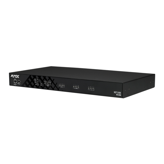
Wiring and Connections Wiring and Connections Overview This chapter provides details, specifications, wiring diagrams, and other important information for all port and connectors available on the NX-series controllers. FIG. 1 displays the NX-series controllers. FIG. 1 NX-series controllers Front Panel Components The following sections list the front panel components on the NX-series controllers. -
Page 27: Usb Port
Wiring and Connections USB Port The front panel of all models features one Type-A USB port you can use to connect a mass storage device for loading .tkn files, reading or writing configuration files and log files, or updating the firmware on the unit. Note: This USB port only supports a FAT32 file system. -
Page 28: Poe General Status Format
General Status LEDs The General Status LEDs include the Link/Activity, Status, Output, and Input LEDs. These LEDs appear on all models of NX-series controllers. FIG. 6 displays the General Status LEDs for each NX-series controller. NX-1200 NX-2200/3200/4200 FIG. 6 General Status LEDs ... -
Page 29: Icslan Leds
RS-232, 422, or 485 data (red = TX, yellow = RX). The light toggles on when a data packet is sent or received. There are two sets of eight SERIAL LEDs on the NX-3200 and NX-4200. The NX-2200 has two sets of four LEDs. The NX-1200 has two sets of two LEDs (see FIG. 8). NX-2200... -
Page 30: Ir/Serial Leds
IR/SERIAL LEDs I/O LEDs The I/O LEDs light yellow to indicate that the corresponding I/O port is active. There are eight I/O LEDs on the NX-3200 and NX-4200. The NX-1200 and NX-2200 has four I/O LEDs (see FIG. 9). NX-2200 NX-3200/4200 NX-1200 FIG. -
Page 31: Rear Panel Components
RS-232 Ports The RS-232 ports (ports 2-4 and 6-8 on the NX-3200/4200; ports 2-4 on the NX-2200; port 2 on the NX-1200) are 5-pin 3.5 mm mini-Phoenix (male) connectors used for connecting A/V sources and displays. These ports support most standard RS-232 communication protocols for data transmission. -
Page 32: Rs-232/422/485 Ports
Wiring and Connections RS-232/422/485 Ports The RS-232/422/485 ports (ports 1 and 5 on the NX-3200/4200; port 1 on the NX-1200/2200) are 10-pin 3.5 mm mini-Phoenix (male) connectors used for connecting A/V sources and displays. By default, these ports are RS-422- and RS-485-disabled ports. -
Page 33: Relay Ports
When used for outputs, the I/O port acts as a switch to GND and is rated for 200mA @ 12 VDC. The NX-1200 and NX-2200 can use up to 4 I/O ports The NX-3200 and NX-4200 can use up to 8 I/O ports ... -
Page 34: Ir/Serial Port: Connections And Wiring
You can also connect a data 0 - 5 VDC device to these ports. NX-3200 and 4200 units each ship with two CC-NIRC IR Emitters (FG10-000-11). NX-1200 and 2200 units ship with one emitter each. -
Page 35: Axlink Port And Led (4-Pin Captive-Wire)
The AxLink port can be used to supply power to downstream AxLink-compatible devices as long as the maximum current draw is less than 1.5 Amps on the NX-1200 and NX-2200, and 3 Amps on the NX-3200 and NX-4200. To isolate the central controller from high in-rush current, AxLink devices, or potential power faults on the AxLink bus, it is strongly recommended that you power external AxLink devices from an independent power supply. -
Page 36: Sdhc Card Slot
Wiring and Connections FIG. 21 provides wiring requirements for the AxLink connector: To the Controller’s To the external AxLink device AxLink/PWR connector Top view Top view FIG. 21 Mini-Phoenix connector wiring diagram (direct data and power) To use the 4-pin 3.5 mm mini-Phoenix (male) captive-wire connector for data communication and power transfer, the incoming PWR and GND cable from the 12 VDC-compliant power supply must be connected to the AxLink cable connector going to the central controller. -
Page 37: Configuration Dip Switch
Switch for Boot from External SD Card (only applicable to the NX-3200 and NX-4200.) Note: The Configuration DIP Switch is located on the front panel of the NX-1200 and not the rear panel. FIG. 24 displays the Configuration DIP Switch for the NX-series controllers. -
Page 38: Using The Icslan Network
FIG. 28 ID pushbutton Note: The ID pushbutton is located on the front panel of the NX-1200 and not on the rear panel. Switching to Static or Dynamic IP Addressing. To toggle between static or dynamic IP addressing, the controller cannot be currently booting or it must be in ID Mode. -
Page 39: Lan 10/100 Port
Wiring and Connections LAN 10/100 Port All NX-series controllers feature a LAN 10/100 port to provide 10/100 Mbps communication via Category cable. This is an Auto MDI/MDI-X enabled port, which allows you to use either straight-through or crossover Ethernet cables. The port support IPv4 and IPv6 networks, as well as HTTP, HTTPS, Telnet, and FTP. -
Page 40: Input Pwr Connector
Wiring and Connections INPUT PWR Connector All NX-series controllers feature a 2-pin 3.5 mm Phoenix connector with screw retention for providing DC power to the controller. The suggested power supply for the NX-series controllers is a 13.5 VDC 6.6 A output, suitable for 50° C. An AC power connector is also available for the NX-4200. - Page 41 Wiring and Connections Hardware Reference Guide - NX-Series NetLinx Integrated Controllers...
- Page 42 - Schedules and registration for any AMX University course - Travel and hotel information - Your individual certification requirements and progress 3000 RESEARCH DRIVE, RICHARDSON, TX 75082 USA • 800.222.0193 • 469.624.8000 • 469-624-7153 fax • 800.932.6993 technical support • www.amx.com...
Need help?
Do you have a question about the NX-1200 and is the answer not in the manual?
Questions and answers