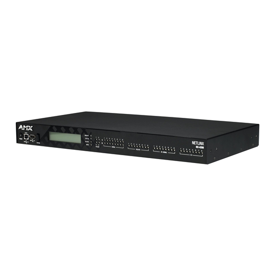
AMX NX-1200 Hardware Reference Manual

AMX NX-1200 Hardware Reference Manual

Integrated controller
Table of Contents

Advertisement

H A RDW A RE REF EREN CE M A N UA L
N E T LI N X N X S E R I ES
I N TE G RATED C O N T RO L LE RS
NX -1 20 0, N X- 220 0, N X- 320 0, N X-4 200

Advertisement

Table of Contents
loading

Summary of Contents for AMX NX-1200

  • Page 1 H A RDW A RE REF EREN CE M A N UA L N E T LI N X N X S E R I ES I N TE G RATED C O N T RO L LE RS NX -1 20 0, N X- 220 0, N X- 320 0, N X-4 200...
  • Page 2 COPYRIGHT NOTICE AMX© 2015, all rights reserved. No part of this publication may be reproduced, stored in a retrieval system, or transmitted, in any form or by any means, electronic, mechanical, photocopying, recording, or otherwise, without the prior written permission of AMX. Copyright protection claimed...
  • Page 3 Anyone performing field maintenance on AMX equipment should use an appropriate ESD field service kit complete with at least a dissipative work mat with a ground cord and a UL listed adjustable wrist strap with another ground cord WARNING: Do Not Open! Risk of Electrical Shock.
  • Page 4: Table Of Contents

    What’s New? ........................8 Two Discrete Network Interfaces (NICs) ....................8 Using the ICSLAN Network ........................8 Automatic Binding of AMX Devices on ICSLAN..................8 Support for IPv6 Networks ........................8 Link-Local Fallback in DHCP Mode......................8 Wired 802.1X Support ..........................8 ID Pushbutton Functionality........................
  • Page 5 Table of Contents Mounting the Controller ....................21 Installing the Controller into an Equipment Rack ................21 Rack Mount Safety Instructions ......................21 Mounting the NX-1200 ......................... 22 Wiring and Connections ..................23 Overview .......................... 23 Front Panel Components....................23 Power Button ............................23 Program Port ............................
  • Page 6 Table of Contents IPv6..................................35 INPUT PWR Connector.......................... 35 Preparing Captive Wires ............................. 35 Wiring a Power Connection ..........................35 Installation of the USB Gadget Serial Driver for Windows 8.x – 32/64-Bit Operating Systems ......................37 Overview ......................... 37 Disabling Driver Signature Verification Procedures ............37 Installing the Gadget Serial Driver.................
  • Page 7: Overview

    The NX-series of NetLinx Integrated Master Controllers can be programmed to control Ethernet, RS-232/422/485, Relay, IR, and Input/Output devices, as well as other AMX devices connected via AxLink, through the use of both NetLinx and Java programming languages. NetLinx programs are developed using the NetLinx Studio application version 4.x. Java programs are developed using the Cafe Duet application.
  • Page 8: What's New

    Serial Ports Differences Unlike current NI controllers, not all serial ports on the X-series controllers support RS-422 and RS-485. The NX-1200 and NX- 2200 have one serial port that supports RS-232/422/485, and the NX-3200 and NX-4200 have two. The rest of the serial ports (1 on the NX-1200, 3 on the NX-2200 and 6 on the NX-3200 and NX-4200) support only the RS-232 protocol.
  • Page 9: Copy And Clone Configuration

    Overview Copy and Clone Conf iguration On any X-Series controller, configuration information can be exported to and imported from a USB storage device. There are two different levels of configuration export: “COPY” and “CLONE”. See the NX Series NetLinx Integrated Controllers WebConsole & Programming Guide for information on using the EXPORT CONFIG and EXPORT CLONE telnet commands.
  • Page 10: Features

    2 IR / Serial ports 4 Digital I/O ports 1 AxLink port 1 LAN Ethernet port 1 IR Receiver port capable of interfacing with an AMX IR03 1 USB 2.0 host port 1600 MIPS 512 MB RAM 4 GB Internal MicroSD Memory Card...
  • Page 11: Nx-1200

    AMX Device Discovery enabled NX-1200 The NX-1200 (FG2106-01) has 512MB of on-board RAM, a 4GB CompactFlash card, and is Device Discovery enabled to simplify programming by standardizing device and function definitions, default touch panel button assignments, and control and feedback methods.
  • Page 12: Nx-1200 Specifications

    Overview NX-1200 Specif ications NX-1200 Specif ications Dimensions (HWD): 1.645" x 5.8" x 5.15" (41.78mm x 147.32mm x 130.81mm) RU: 1/3 Active Power • DC input voltage (typical): 12 V Requirements: • DC current draw: 200 mA @ 12 V •...
  • Page 13: Nx-2200

    • L/A (link/activity) - Green LED lights On when the Ethernet cables are connected and terminated correctly, and blinks when receiving Ethernet data packets. Power Connection: 2-pin 3.5 mm mini-Phoenix (male) connector with retention screws provides power to the NX-1200. General Specif ications: Operating •...
  • Page 14: Nx-2200 Specifications

    Overview NX-2200 Specif ications NX-2200 Specif ications Dimensions (HWD): 1.766" x 17" x 9.12" (44.85mm x 431.8mm x 231.64mm) RU: 1 Active Power • DC input voltage (typical): 12 V Requirements: • DC current draw: 250 mA @ 12 V •...
  • Page 15: Nx-3200

    FIG. 4 NOTE: Verify you are using the latest NX f irmware for the on-board Master. Verify you are using the latest version of NetLinx Studio 4.0 (available for download from www.amx.com). Hardware Reference Guide - NX-Series NetLinx Integrated Controllers...
  • Page 16: Port Numbers

    Overview Port Numbers The following table lists the port numbers for the NX-3200: NX-3200 Port Numbers RS-232 RS-422/485 IR/Serial Relay 2-4, 6-8 1, 5 11-18 NX-3200 Specif ications NX-3200 Specif ications Dimensions (HWD): 1.766" x 17" x 9.12" (44.85mm x 431.8mm x 231.64mm) RU: 1 Active Power •...
  • Page 17 Overview NX-3200 Specif ications (Cont.) Rear Panel Components: (Cont.) Relays (Port 21): 8-channel single-pole single-throw relay port Each relay is independently controlled. Supports up to 8 independent external relay devices Channel range = 1-8 Each relay can switch up to 24 V or 28 V @ 1 A Two 8-pin 3.5 mm mini-Phoenix (male) connectors provide connection to relays...
  • Page 18: Nx-4200

    The NX-4200’s on-board Master also provides the ability to update installed control card firmware. NOTE: Verify you are using the latest NX f irmware for the on-board Master. Verify you are using the latest version of NetLinx Studio 4.0 (available for download from www.amx.com). Port Numbers...
  • Page 19: Nx-4200 Specifications

    Overview NX-4200 Specif ications NX-4200 Specif ications Dimensions (HWD): 1.766" x 17" x 9.18" (44.85mm x 431.8mm x 233.17mm) RU: 1 Active Power • DC input voltage (typical): 12 V Requirements: • DC current draw: 200 mA @ 12 V •...
  • Page 20: Other Amx Equipment

    • 2 removable rack ears Other AMX Equipment This section lists optional AMX accessories and part numbers you may find useful for your NX controller. You can use all listed optional accessories with each model of NX controller. PSN6.5 - 6.5 A Power Supply (FG423-41) ...
  • Page 21: Mounting The Controller

    Overview Serial, IR, AxLink, and PoE Port Diagnostics When a string is sent to a serial port or an IR pulse to an IR port, the X-Series controllers can detect and report if the port being used is in a fault condition. The controllers can also detect certain fault conditions on the AxLink bus or Power-over-Ethernet (PoE) subsystem.
  • Page 22: Mounting The Nx-1200

    Consult the Mounting Options for V Style Modules Quick Start Guide included with the respective mounting kit for instructions on mounting the NX-1200. The NX-1200 also has rubber feet which you can apply to the bottom of the unit for table-top mounting.
  • Page 23: Wiring And Connections

    Wiring and Connections Wiring and Connections Overview This chapter provides details, specifications, wiring diagrams, and other important information for all port and connectors available on the NX-series controllers. FIG. 7 displays the NX-series controllers. NX-series controllers FIG. 7 Front Panel Components The following sections list the front panel components on the NX-series controllers.
  • Page 24: Usb Port

    Wiring and Connections USB Port The front panel of all models features one Type-A USB port you can use to connect a mass storage device for loading .tkn files, reading or writing configuration files and log files, or updating the firmware on the unit. NOTE: This USB port only supports a FAT32 f ile system.
  • Page 25: Poe Port Status

    General Status LEDs The General Status LEDs include the Link/Activity, Status, Output, and Input LEDs. These LEDs appear on all models of NX-series controllers. FIG. 12 displays the General Status LEDs for each NX-series controller. NX-1200 NX-2200/3200/4200 General Status LEDs FIG. 12 Link/Act - Lights green when the link is up and toggles off when a data packet is sent or received.
  • Page 26: Icslan Leds

    485 data (red = TX, yellow = RX). The light toggles on when a data packet is sent or received. There are two sets of eight SERIAL LEDs on the NX-3200 and NX-4200. The NX-2200 has two sets of four LEDs. The NX-1200 has two sets of two LEDs (see FIG.
  • Page 27: Irrx Port

    RS-232 Ports The RS-232 ports (ports 2-4 and 6-8 on the NX-3200/4200; ports 2-4 on the NX-2200; port 2 on the NX-1200) are 5-pin 3.5 mm mini-Phoenix (male) connectors used for connecting A/V sources and displays. These ports support most standard RS-232 communication protocols for data transmission.
  • Page 28: Rs-232/422/485 Ports

    RS-232/422/485 Ports The RS-232/422/485 ports (ports 1 and 5 on the NX-3200/4200; port 1 on the NX-1200/2200) are 10-pin 3.5 mm mini-Phoenix (male) connectors used for connecting A/V sources and displays. By default, these ports are RS-422- and RS-485-disabled ports.
  • Page 29: Relay Ports

    When used for outputs, the I/O port acts as a switch to GND and is rated for 200mA @ 12 VDC.  The NX-1200 and NX-2200 can use up to 4 I/O ports  The NX-3200 and NX-4200 can use up to 8 I/O ports ...
  • Page 30: Ir/Serial Port: Connections And Wiring

    These ports accept an IR Emitter (CC-NIRC) that mounts onto the device's IR window, or a mini-plug (CC-NSER) that connects to the device's control jack. You can also connect a data 0 - 5 VDC device to these ports. NX-3200 and 4200 units each ship with two CC-NIRC IR Emitters (FG10-000-11). NX-1200 and 2200 units ship with one emitter each.
  • Page 31: Axlink Port And Led (4-Pin Captive-Wire)

    The AxLink port can be used to supply power to downstream AxLink-compatible devices as long as the maximum current draw is less than 1.5 Amps on the NX-1200 and NX-2200, and 3 Amps on the NX-3200 and NX-4200. To isolate the central controller from high in-rush current, AxLink devices, or potential power faults on the AxLink bus, it is strongly recommended that you power external AxLink devices from an independent power supply.
  • Page 32: Sdhc Card Slot

    Switch for Boot from External SD Card (only applicable to the NX-3200 and NX-4200.)  NOTE: The Conf iguration DIP Switch is located on the front panel of the NX-1200 and not the rear panel. FIG. 30 displays the Configuration DIP Switch for the NX-series controllers.
  • Page 33: Icslan Ports

    The NX-2200/3200/4200 controllers have two types of Ethernet ports: LAN and ICSLAN. The LAN port is used to connect the master to an external network, and the ICSLAN ports are used to connect to other AMX equipment or third-party A/V equipment.
  • Page 34: Id Pushbutton

    ID pushbutton FIG. 34 NOTE: The ID pushbutton is located on the front panel of the NX-1200 and not on the rear panel. Switching to Static or Dynamic IP Addressing. To toggle between static or dynamic IP addressing, the controller cannot be currently booting or it must be in ID Mode. If these conditions are met, holding the ID pushbutton for 10 seconds changes the current IP addressing mode.
  • Page 35: Ipv4

    Wiring and Connections The LAN port gets its IP address(es) in one or more of the following ways: IPv4 Static assignment by the user  Dynamic assignment by an IPv4 DHCP server  Link local as a fall back when configured for DHCP but unable to successfully obtain address ...
  • Page 36 Wiring and Connections Hardware Reference Guide - NX-Series NetLinx Integrated Controllers...
  • Page 37: Installation Of The Usb Gadget Serial Driver For Windows 8.X - 32/64-Bit Operating Systems

    Overview With AMX's NX-Series Controllers, the USB Gadget Serial driver must be installed differently for users running the Windows 8.X 32/64 bit Operating Systems. This driver is necessary for users connecting to the USB programming port on the front panel of the NX-Series Controllers.
  • Page 38 Installation of the USB Gadget Serial Driver for Windows 8.x – 32/64-Bit Operating Systems When the Control Panel opens, select the General section. (Win 8.0 users can skip to step 6.) FIG. 42 displays the PC Settings options. PC Settings FIG.
  • Page 39 Installation of the USB Gadget Serial Driver for Windows 8.x – 32/64-Bit Operating Systems Once selected, you will see an Advanced startup section appear. Click on the Restart now button. FIG. 45 displays the Advanced startup page. Advanced Startup page FIG.
  • Page 40 Installation of the USB Gadget Serial Driver for Windows 8.x – 32/64-Bit Operating Systems After your PC restarts, you will see a list of startup settings that you can change. Press F7 to select the "Disable driver signature enforcement" setting. FIG.
  • Page 41: Installing The Gadget Serial Driver

    Installation of the USB Gadget Serial Driver for Windows 8.x – 32/64-Bit Operating Systems Installing the Gadget Serial Driver The NetLinx Studio v4.0 setup program installs the Gadget Driver into the Windows\INF directory. After completing the Disabled Driver Signature Verification procedures, use a Type-A-to-Type-B USB cable to connect your PC to the front program port on the NX controller (see FIG.
  • Page 42: Manually Installing/Updating The Usb Driver

    If you are still having problems with Windows 8.x finding the Gadget Serial driver files, the NetLinx Studio installer will copy a set of the driver files into the following directory: C:\Program Files (x86)\AMX Control Disc\NetLinx Studio 4\USBGadgetDriver From the Windows Control Panel, select Hardware and Sound, then select the Device Manager option. You can manually update the driver by performing the following steps: Click the Ports branch and select the Gadget Serial driver.
  • Page 43 © 2015 Harman. All rights reserved. NetLinx, AMX, AV FOR AN IT WORLD, and HARMAN, and their respective logos Last Revised: are registered trademarks of HARMAN. Oracle, Java and any other company or brand name referenced may be 9/21/2015 trademarks/registered trademarks of their respective companies.

This manual is also suitable for:

Nx-4200Nx-2200' nx-3200

Table of Contents