Table of Contents
Advertisement
Quick Links
MODEL Mini-ICS
OXYGEN ANALYZER / CONTROLLER – PERCENT
Neutronics
Reference Manual for
Installation and
Operation Instructions
OPERATIONS MANUAL
Manual Part Number: 5-06-4900-53-0
Document Control Number: MN-A-0031
Revision Level: C – ECO 044952
Revision Date:
Phone: 610.524.8800 • Fax: 610.524.8807 • Email: info@neutronicsinc.com
RANGE
MODEL Mini-ICS O
P
!
NORMAL
May 08, 2018
456 Creamery Way, Exton, PA 19341
www.neutronicsinc.com
Controller
2
O
ERCENT
XYGEN
20.9
FAULT
LOW FLOW
O
MODE
ALARM
2
Advertisement
Table of Contents
Troubleshooting

Subscribe to Our Youtube Channel
Related Manuals for Bacharach Neutronics Mini-ICS


Summary of Contents for Bacharach Neutronics Mini-ICS
- Page 1 MODEL Mini-ICS OXYGEN ANALYZER / CONTROLLER – PERCENT RANGE Neutronics MODEL Mini-ICS O Controller ERCENT XYGEN 20.9 FAULT NORMAL LOW FLOW ALARM Reference Manual for Installation and MODE Operation Instructions OPERATIONS MANUAL Manual Part Number: 5-06-4900-53-0 Document Control Number: MN-A-0031 Revision Level: C –...
-
Page 3: Table Of Contents
Table of Contents TABLE OF CONTENTS ......................... III FOR YOUR SAFETY: ........................... VII WELCOME ............................VIII CHAPTER 1 – INTRODUCTION AND OVERVIEW ............1-1 ..........................1-1 ENERAL ..........................1-2 EATURES ....................1-3 YSTEM ARDWARE VERVIEW 1.3.1 Main Board ........................1-3 1.3.2 Relay Board ........................ - Page 4 2.1.3.1 Oxygen Sensor Input ....................2-6 2.1.3.2 Flow Switch Status Input ..................... 2-6 2.1.3.3 Oxygen Alarm Relay Outputs ..................2-6 2.1.3.4 Inert Gas Control Relay Outputs ................. 2-7 2.1.3.5 Fault Relay Outputs ..................... 2-7 2.1.3.6 Remote Calibration Relay Outputs ................2-7 2.1.3.7 Analog Voltage Output ....................
- Page 5 4.1.1.5 User Setup 5: Display Range Setup................4-2 4.1.1.6 User Setup 6: RS-232 Baud Rate................4-2 4.1.1.7 User Setup 7: Serial Output Format................4-2 4.1.1.8 User Setup 8: Sensor Disconnect Detection Test............4-2 4.1.1.9 User Setup 9: Minimum Analog Output Voltage Concentration ........4-2 4.1.1.10 User Setup 10: Maximum Analog Output Voltage Concentration .......
- Page 6 4.3.1.18 Fault Code 31 – Factory Setup Mode active ............. 4-22 4.3.1.19 Fault Code 32 – Program Starting................4-22 CHAPTER 5 – APPENDICES ..................5-1 A – S ..................... 5-1 PPENDIX PARE ARTS B - S ....................5-2 PPENDIX PECIFICATIONS ANALYZER FACTORY CONFIGURATION SETTINGS APPENDIX C –...
-
Page 7: For Your Safety
For Your Safety: PLEASE READ THIS MANUAL IN ITS ENTIRETY BEFORE ATTEMPTING INSTALLATION OR OPERATION! Attempting to operate the Model 1100 without fully understanding its features and functions may result in unsafe conditions • Always use protective eye wear and observe proper safety procedures when working with pressurized gases. -
Page 8: Welcome
WELCOME Thank you for purchasing the Model Mini-ICS Analyzer for percent range Oxygen measurement. The Model Mini-ICS Compact Analyzer is a user friendly, microprocessor-controlled Oxygen measuring instrument. It has many features to offer the user, which will be described in this manual. -
Page 9: Chapter 1 - Introduction And Overview
1 – I HAPTER NTRODUCTION AND VERVIEW General The Model Mini-ICS [Inert Gas Control System] analyzer by Neutronics offers a cost effective solution in a small package for industrial process Oxygen measurement and inert gas control applications for flash-fire/explosion prevention, or product quality. The Model Mini-ICS is a custom analytical instrument, designed to accurately measure 0.1 to 50.0% Oxygen, and provide direct control of Oxygen levels in your process by controlling inert gas purging. -
Page 10: Features
System Hardware Overview Features The Model Mini-ICS analyzer module is designed to be flush mounted to a panel or console. Packaging options available from Neutronics Inc. include General Purpose and Explosion Proof surface-mount enclosures, and custom rack-mount designs. Because of the small size of the Model Mini-ICS analyzer, the basic panel-mount unit can be integrated into a variety of equipment or control panels. -
Page 11: System Hardware Overview
System Hardware Overview System Hardware Overview Control Panel Power Supply Board Relay Board Chassis Main Board Display Board Figure 3 – Basic analyzer components 1.3.1 Main Board The main board houses the microprocessor, and supporting electronics for controlling the operation of the Model Mini-ICS Analyzer. The main board receives the sensor signal and flow switch inputs, and provides the control and display functions of the analyzer. -
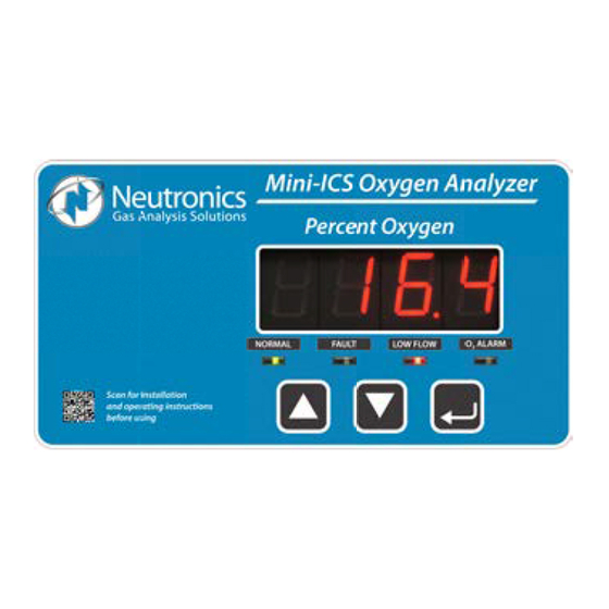
Page 12: Control Panel
System Hardware Overview 1.3.5 Control Panel The Control Panel serves as the main user interface. The Control Panel features the keypad (ramp-UP, ramp-DOWN, and MODE keys) and the status LED’s. The control panel is designed to be splash and water-resistant. At the four corners of the panel are the #8-32 mounting studs, which allow flush mounting of the instrument to a control or equipment panel. - Page 13 System Hardware Overview 4-20 mA Output RS 232 COM Line Analog Voltage Output Range ID Output Fault and Remote Calibration Relay Outputs Alarm & Inert Gas Control Relay Outputs Relay Board Sensor Line Power Main Board Filter Supply Flow Switch Display Mains Power Board...
-
Page 14: System Inputs And Outputs
System Hardware Overview System Inputs and Outputs 1.4.1 Oxygen Sensor Input The Oxygen Sensor electrical input is used to indicate the Oxygen level concentration in a process vessel headspace, or a process gas stream. Sensors are available to measure the Oxygen concentration in percent by volume or partial pressure in the ranges from 0.1% to 25.0%, and 0.1% to 50.0%. -
Page 15: Remote Calibration Relay Output
System Hardware Overview 1.4.6 Remote Calibration Relay Output The Remote Calibration relay is used to activate a valve that flows calibration gas to the sensor during gas calibration. This is a convenience item for applications where the sensor/sampling system is a long distance from the analyzer. The Calibration relay is mapped to the analyzer Calibration function. -
Page 17: Front Panel User Interface
Front Panel User Interface 1.5.1 The “UP” Pushbutton The “UP” pushbutton can be used to program the Mini-ICS Analyzer via the front panel. This momentary push-button soft key is used to enter incremental information. Its function is menu- driven. 1.5.2 The “DOWN” Pushbutton The “DOWN”... -
Page 18: Installing The Analyzer
Installing the Analyzer 2 – S HAPTER YSTEM NSTALLATION TART Installing the Analyzer PANEL CUTOUT Figure 6 – Installation outline Manual Part Number: Revision Level: C Revision Date: Page 5-06-4900-53-0 ECO 044952 May 08, 2018... -
Page 19: Step 1 - Locate And Mount The Analyzer Unit
Installing the Analyzer 2.1.1 Step 1 – Locate and Mount the Analyzer unit The Model Mini-ICS is designed to be mounted flush to the surface of equipment or on a control panel. Select a suitable location for the Model Mini-ICS analyzer unit where the digital display and status LED’s will be easy to read, and the interface buttons on the display panel will be easy to access. -
Page 20: Step 2 - Install The Oxygen Sensor
Installing the Analyzer 2.1.2 Step 2 – Install the Oxygen Sensor The Model Mini-ICS will be supplied with the Model GP, the Model CAG-250, or the Model IT Oxygen sensor, depending on the application. In most cases, it will also be supplied with a Neutronics-specified Sampling system. - Page 21 Installing the Analyzer Power In Sensor/Flow Switch In Alarms/Range ID Out Serial/Analog Out 11- 30 VDC INPUT, 2.5W VDC+ 90- 264 VAC INPUT, 2.5VA AC-L AC-N Range Fault O2 ALARM ICS VALVE V-Out VALVE NC NO C NO NC NO C NO Bat.
-
Page 22: Oxygen Sensor Input
Installing the Analyzer 2.1.3.1 Oxygen Sensor Input Connections to the sensor are made at terminal block TB4 on the rear of the analyzer chassis. Be certain to match the terminal pins against the terminal ID label on the top of the analyzer chassis. Refer to Appendix F –... -
Page 23: Inert Gas Control Relay Outputs
Installing the Analyzer 2.1.3.4 Inert Gas Control Relay Outputs Connections from the Inert Gas Control relay contacts to a Neutronics Inc. Inert Gas Control solenoid valve are made at terminal block TB2 on the rear of the analyzer chassis, for stand-alone control of Oxygen in a process vessel or stream. -
Page 24: Analog Voltage Output
Installing the Analyzer 2.1.3.7 Analog Voltage Output Connections from the Analog Voltage output to the user’s auxiliary equipment are made at terminal block TB3 on the rear of the analyzer chassis. Be certain to match the terminal pins against the terminal ID label on the top of the analyzer chassis. -
Page 25: Rs-232 Service Port
Installing the Analyzer 2.1.3.10 RS-232 Service Port Connections from the Range ID output to the user’s auxiliary equipment are made at terminal block TB3 on the rear of the analyzer chassis. Be certain to match the terminal pins against the terminal ID label on the top of the analyzer chassis. -
Page 26: Mains Power
Installing the Analyzer 2.1.3.12 Mains Power Connections for Mains Power input are made at terminal block TB1 on the rear of the analyzer chassis. Be certain to match the terminal pins against the terminal ID label on the top of the analyzer chassis. -
Page 27: Starting Up And Commissioning The System
Starting up and Commissioning the System Starting up and Commissioning the System STEP 1: POWER UP STEP 2: INITIAL CALIBRATION STEP 3: SET OXYGEN ALARM & INERT GAS CONTROL LIMITS Figure 10 – start-up outline The Model Mini-ICS is shipped ready to use, right from the carton. Factory default configuration settings are listed in Appendix C for your information. -
Page 28: Step 2 - Calibrate The Unit
Starting up and Commissioning the System 2.2.2 STEP 2 – Calibrate the Unit Refer to section 3.2.1 for detailed analyzer calibration instructions. All units are shipped freshly calibrated. If, however, the unit is stored for more than thirty days, a calibration may be required for best accuracy. -
Page 29: Chapter 3 - Analyzer Operation
RUN Modes 3 – A HAPTER NALYZER PERATION System Organization The Model Mini-ICS has two types of operational modes – User-type, and Run-type. “User” modes are initiated and controlled by the user, and are used to setup and maintain the analyzer. “Run” modes are accessed automatically by the Model Mini-ICS during normal operation, according to its programming, and its configuration parameters. -
Page 30: Procedure For Calibrating The Model Mini-Ics
RUN Modes 3.2.1.3 Procedure for calibrating the Model Mini-ICS 3.2.1.3.1 Apply calibration gas to the Oxygen Sensor Apply calibration gas to the Oxygen Sensor at a similar flow rate and pressure to that of the sampled gas. Be sure to flow calibration gas to the sensor until the display has stabilized to allow calibration gas to sweep out the sample lines. -
Page 31: Set O
RUN Modes 3.2.2 SET O ALARM Mode To enter Set O Alarm mode from any Run mode using the keypad; scroll through the User Mode menu by pressing momentarily the “MODE” button two (2) times, until the 7-segment alphanumeric display reads “AL” (Set O Level). -
Page 32: Run Modes
RUN Modes RUN Modes After power-up and self-test, and analyzer immediately enters into one of its Run modes – Normal, Alarm Active, Inerting Control Active, or Fault Active. The Run mode active at any time, provided no manual input is received at the front panel or service port, is determined by the analyzer setup parameters entered at the factory, and by the user, compared against the analyzer’s monitored inputs and other monitored hardware in real time. -
Page 33: Fault Active Mode
RUN Modes The 7-segment alphanumeric display will flash and continue to display the measured Oxygen level. The “NORMAL” indicator LED will remain lit. The Inerting Control relays will change state according to the analyzer configuration. The Inerting Control function will be cleared automatically when measured Oxygen concentration falls below the set threshold value of the Low Inerting Control Limit. -
Page 35: Chapter 4 - Maintenance And Troubleshooting
4 – M HAPTER AINTENANCE AND ROUBLESHOOTING System Setup The Model Mini-ICS is shipped ready to install and operate with complete factory configuration already programmed and tested. The user may however wish to change the system configuration to suit the application of the analyzer. Some setup parameters may be changed by the user via the front panel keypad. -
Page 36: User Setup 2: O2 Alarm Relays Ascending Trip
System Setup 4.1.1.2 User Setup 2: O2 Alarm Relays Ascending Trip. This parameter allows the user to set the O Alarm relay to trip either ascending or descending. Ascending trip is defined as; the relay is set to active when the Oxygen level is above the O Alarm level set point. -
Page 37: User Setup 11: Minimum Analog Output Current Concentration
System Setup Valid Settings: Any oxygen concentration between 0 to 100% Note: The Analog Output scale may be inverted if the voltage in User Setup 9 is set to be higher than voltage in User Setup 10. 4.1.1.11 User Setup 11: Minimum Analog Output Current Concentration This parameter is only valid if Menu 5 is set to option 5 –... -
Page 38: Troubleshooting Your Hyperterminal Interface
System Setup On your PC computer, open HyperTerminal: Navigate from the Windows desktop – Select Start → Programs → Accessories → Communications → HyperTerminal In HyperTerminal, create and configure a new connection – follow the prompts: PROMPT YOU ENTER CONNECTION NAME 1100ICS CONNECT TO COM1, or other available... -
Page 39: Standard Level Access
System Setup Advanced Level-2 Access: Allows access to vital control areas via password. 4.1.2.4 Standard Level Access Standard Access level is the default level of access to the Model Mini-ICS available to the user via a host computer or printer over a standard RS-232 serial interface. In Standard Level access, the user can make inquiries about Oxygen concentration, sensor signal level, and other parameters for system servicing, and troubleshooting. - Page 40 System Setup Active Fault codes Active Fault code descriptions Long software version Unit Serial Number STANDARD ACCESS level commands – continued: TYPED COMMAND DESCRIPTION OF QUERIED FUNCTION Manual O Alarm relay override Manual Fault relay override Manual Remote Calibration relay override Manual Inert Gas Control relay override Cancel all manual relay overrides Helpful Hint: Standard Level Access commands 1 through 5 can be used to manually cycle valves,...
- Page 41 System Setup 4.1.2.4.2 Human Readable Data Format – SSERFMT=1 The factory default format is Human Readable and can be changed via the analyzer front panel, or through the RS-232 interface in Standard Access level. Human Readable data is presented in dynamic columns (columns appear only when data is present).
-
Page 42: Advanced Level 1 Access
System Setup 4.1.2.5 Advanced Level 1 Access Advanced Level-1 access is the user setup mode, and is available to the user via a PC or directly at the Model Mini-ICS analyzer control panel (section 14.1.1). Access to Advanced Level-1 can be accomplished on a PC by typing “setup”... -
Page 43: Setting Up The Model Mini-Ics - The Rs-232 User Setup Menu
System Setup SETTING UP THE MODEL Mini-ICS – The RS-232 User Setup Menu 4.1.2.7 The RS-232 User Setup menu U00 is the “Home” screen in Advanced Level-1 access (section 4.1.2.5), and provides access to all the parameters that may need to be adjusted by the user. The interactive menu is initiated by typing “setup”... - Page 44 System Setup 4.1.2.9.3 O Alarm Level Setting This setting sets the threshold level for the O Alarm relay. Depending on whether or not it is set to ascending or descending, the O Alarm relay becomes active when the Oxygen concentration is above or below this threshold level.
-
Page 45: U30) Analog Output Setup Menu
System Setup 4.1.2.10 (U30) Analog Output Setup Menu The RS-232 Analog Output Setup menu U30 provides access to all of the settings related to the Analog Voltage Output (TB3-pin5, TB3-pin6) and Analog Current Output (TB3-pin7, TB3-pin8). It is accessed from the Setup Main Menu by typing “3” on the RS-232 terminal. To navigate backwards, use the <Esc>... - Page 46 System Setup 4.1.2.10.6 Calibrate 0 To 1 Volt Output This menu calibrates the 0-1V Analog Voltage Output. A digital multi-meter set to measure volts must be attached to TB3-pin5 and TB3-pin6. Jumper RA must be open and RB must be shorted (section 4.1.3).
-
Page 47: U04) Display/Analog Output Range
System Setup 4.1.2.10.14 Test with Percentage Full Scale This menu may be used to test the Analog Current and Voltage output in terms of percentage full scale. Any percentage between 0.0 and 100.0 may be entered at the prompt. Navigate from Analog Output Setup menu to the Analog Output Calibration menu by typing “3”... -
Page 48: U60) Front Panel Locks Menu
System Setup 4.1.2.12.2 Automatic Serial Output Format This menu sets the format of the automatic timed RS-232 serial output. The timed serial output format may be set to 0 (Output on Request), 1 (Human Readable), 2 (Machine Code), 3 (Machine Code with Checksum), 4 (Tab Delimited). -
Page 49: U70) Auto Calibration Setup Menu
System Setup 4.1.2.13.6 User Setup Password The Front Panel User Setup mode may be given limited access by setting up as password. The password may be a number between 1 and 9999. The user then enters this number from the front panel to initiate the Front Panel User Setup mode. -
Page 50: Sensor Disconnect Test
System Setup 4.1.2.14.1 Relay on to Start Sample Delay This setting determines the delay between the activation of the Calibration relay and the start of calibration gas sampling. The purpose of this delay is to give enough time for the calibration gas to propagate through to the sensor before the Model Mini-ICS starts reading the calibration gas. -
Page 51: Auto Return To Run Mode Time
System Setup 4.1.2.18 Auto Return to Run Mode Time This setting sets the time that the Mini-ICS will stay in Front Panel Calibration mode or Front Panel User Setup mode without any user input. The purpose of this feature is that if a user enters either mode, and forgets to exit, the setting will automatically send the unit back to run mode. - Page 52 System Setup Model Mini-ICS Bottom View Ntron Process Analyzer Division Division of Neutronics Inc. 456 Creamery Way Exton, PA 19341 Jumper access port in analyzer Case (JP4) (JP5) Figure 11 – Range select jumpers SELECT JP4 / JP5 JUMPERS VOLTAGE (1=SHORTED;...
-
Page 53: Routine Periodic Maintenance
Troubleshooting Routine Periodic Maintenance Maintenance for the Model Mini-ICS Oxygen analyzer is very simple. Apart from the normal maintenance for any instrument, such as cleaning the chassis, wiping the display, and replacing the sensor, the Model Mini-ICS does not require any major servicing. Periodic calibration of the sensor on known gas should be performed on a regular basis (see section 4.2). -
Page 54: Troubleshooting
Troubleshooting Troubleshooting 4.3.1 Fault Codes When trouble occurs during normal operation of the Model Mini-ICS, the user has several tools available to aid in isolating the cause(s) of given symptoms. As a starting point, the user may use the front panel to enter into “View Active Faults” mode (section 3.2.5). The user may also view active faults and other useful information via the Service Port (section 4.1.2). -
Page 55: Fault Code 6 - Unstable Calibration Sample
Troubleshooting Fault Code 6 – Unstable Calibration Sample 4.3.1.6 The Unstable Calibration Sample fault indicates that during the “relay on to start sample delay” (section 4.1.2.14.1, and Appendix C), plus the “calibration sample period” (section 4.1.2.14.2, and Appendix C), the analyzer detected a window of variation in the sensor output that exceeded the Standard Deviation Error Limit (section 4.1.2.14.5). -
Page 56: Fault Code 17 - Bad Cell Calibration Coefficient
Troubleshooting Fault Code 17 – Bad cell Calibration Coefficient 4.3.1.12 The Bad cell Calibration Coefficient indicates that during the calibration sample period (section 4.1.2.14.3), the analyzer cannot access all reference data necessary to perform the routine. The presence of this fault indicates corrupted non-volatile data. Please contact the Neutronics Inc. Service Department. -
Page 57: Chapter 5 - Appendices
5 – A HAPTER PPENDICES Appendix A – Spare Parts List PART NUMBER DESCRIPTION Vac Fuses for Power Supply Board (for Vac units only). – 1A, C1-11-1220-03-0 250Vac, Slo-Blo 8-01-1000-02-2 Oxygen Sensor Model GP: 0-25% 6-01-1001-91-0 Oxygen Sensor Model IT: 0-25% C1-16-1000-01-1 Oxygen Sensor Model CAG-250N: 0-100% 5-06-4900-53-0... -
Page 58: Appendixb - Specifications
Appendix B - Specifications Appendix B - Specifications 0 – 1 / 0 – 10 / 0 – 25 / 0 – 50 % Oxygen – Fixed or Auto Range MEASUREMENT: 0.75” 7-segment LED digital display, 4 characters DISPLAY: Displays Oxygen from 0.0 to 50.0 Percent. 0 –... - Page 59 Appendix B - Specifications 31 - 104° F • 5° to 40° C OPERATING TEMPERATURE 5 - 122° F • -15° to 50° C STORAGE TEMPERATURE HUMIDITY 0-95% non-condensing WARM UP TIME 20 seconds to system stabilization 90 – 264 VAC, 47 – 63 Hz, Single Phase, 2.5 POWER AC Unit: Watts...
-
Page 60: Appendix C - Analyzer Factory Configuration Settings
Appendix C – Factory Configuration Settings APPENDIX C – ANALYZER FACTORY CONFIGURATION SETTINGS Supply Voltage 90 – 250 VAC, 50-60HZ 12-36 VDC Sensor Type GP Sensor (Part No: 8-01-1000-02-3) CAG-250 Nylon (Part No: C1-16-1000-01-1) IT (CR) Sensor (Part No: 6-01-1001-91-0) Safety Barrier Type MTL (Passive) STAHL (Passive) - Page 61 Appendix C – Factory Configuration Settings Analog Output Range Setting 0 – 1 Percent Fixed 0 – 10 Percent Fixed 0 – 25 Percent Fixed 0 – 50 Percent Fixed Auto Ranging Rs-232 Baud Rate 300 BPS 1200 BPS 2400 BPS 4800 BPS 9600 BPS 19200 BPS...
-
Page 62: Appendix D - Front Panel Hot-Key Functions
Appendix C – Factory Configuration Settings APPENDIX D – Front Panel Hot-Key Functions For convenience in operating and troubleshooting, the Model Mini-ICS has four Front Panel Hot- Key Functions that can be performed quickly via the front panel without entering the normal Front Panel, or Service Port user menus. -
Page 63: Appendix E - Warranty
Appendix E – Warranty APPENDIX E – Warranty Neutronics warrants to the original purchaser, that the Model Mini-ICS Oxygen analyzer is free from defects in material and workmanship for a period of one (1) year from the date of shipment from Neutronics or from one of Neutronics’... -
Page 64: Appendix G - Mounting Configurations
Appendix E – Warranty APPENDIX G – Mounting Configurations The enclosure requirement for the Model Mini-ICS will be determined by the area classification in which it will be installed. The enclosure type will also affect the user interface with the front panel. The following figures will depict how the interface changes with each enclosure type. -
Page 65: Rack Mount Enclosure
Appendix E – Warranty 5.7.2 Rack Mount Enclosure Users will activate the three push buttons mounted on the enclosure door to interface with the module. Each button corresponds to one button on the front panel and is clearly labelled to indicate its function (“Up”, “Down”, or “Mode”) as shown below. -
Page 66: Explosion Proof Enclosure
Appendix E – Warranty 5.7.3 Explosion Proof Enclosure Model Mini-ICS modules housed in explosion proof enclosures have only two switches to interface with the unit. The left side has a three-position spring return to center from left or right switch. Turning the switch counter clockwise (and releasing) corresponds to incremental up (“UP”), and turning it clockwise (and releasing) corresponds to incremental down (“DOWN”).
Need help?
Do you have a question about the Neutronics Mini-ICS and is the answer not in the manual?
Questions and answers