
Related Manuals for Bacharach Parasense GRM2 CO2 Series


Summary of Contents for Bacharach Parasense GRM2 CO2 Series
- Page 1 GRM2 CO2 REFRIGERANT MONITOR OPERATION & MAINTENANCE MANUAL Models GRM2-104D2-1xxCO2 Doc. Ref. MNGRM2CO2 REV. 3...
- Page 2 GRM2 CO2 Refrigerant Monitor Models GRM2-104D2-1xxCO2 Copyright Notice Copyright © Parasense. All rights reserved. Must not be copied or reproduced without the written permission of Parasense. Disclaimer The information contained within this document is subject to change without notice. While Parasense continue to make the information within this document as accurate as possible, it may contain unintentional typographical or technical errors.
-
Page 3: Table Of Contents
TABLE OF CONTENTS 1 INTRODUCTION ..........................1-1 GENERAL ARRANGEMENT......................1-2 2 INSTALLATION GUIDE ........................2-1 ENCLOSURE DIMENSIONS......................2-1 MONITOR FITTING INSTRUCTIONS ....................2-1 ELECTRICAL REQUIREMENTS ..................... 2-2 MAINS INPUT CONNECTIONS ....................... 2-3 SINGLE GROUND EARTH SCREW CONNECTION ............... 2-3 RELAY CONNECTIONS ........................2-4 EXTERNAL COMMS ........................ - Page 4 SYSTEM TEST - RS485 NETWORKED SAMM ................7-24 SYSTEM TEST – RS485 AMMONIA NETWORKED SAMMS ............7-26 SYSTEM TEST – BACHARACH MGS.150 SENSORS ..............7-28 ZERO CALIBRATION OF SMARTGAS RS485 NETWORK SAMMS..........7-31 FIELD CALIBRATION OF GDS RS485 NETWORK SAMMS ............7-33 CALIBRATION OF BACHARACH MGS.150 NETWORK SENSOR ..........
- Page 5 Apr 2017 2-6: Wiring schematics for Clairair CO2 sensor added. May 2017 Amended field calibration instructions for CO2 sensor. Calibration and test procedures added for Bacharach MGS.150 2-7: sensor March 2018 PS0778 updated to include Bacharach MGS.150 details Parasense logos updated...
-
Page 6: Introduction
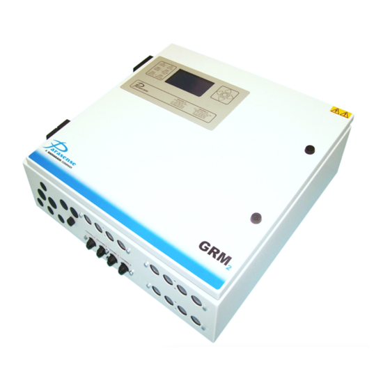
1 INTRODUCTION The Parasense GRM2 CO2 series monitors are advanced refrigerant leak detection devices utilising infrared absorption sensors to analyse air samples. Dependent on model, the monitor will have 4, 8, 12, or 16 individual internal SAMMs (SAMpling Module), each having their own pump and filter. Each SAMM is connected to the area to be sampled by semi-rigid nylon pipework, referred to as freeway. -
Page 7: General Arrangement
GENERAL ARRANGEMENT Operation & Maintenance Manual Doc. Ref. MNGRM2CO2 REV. 3... -
Page 8: Installation Guide
2 INSTALLATION GUIDE ENCLOSURE DIMENSIONS GRM2-104D2- WEIGHT 116CO2 Metric (mm) 22Kg Imperial (In) 21.7 19.7 23.6 17.7 25.6 24.4 27.5 48.4lb The monitor enclosure is not intended for external use. Where possible the enclosure and pipework should be positioned in areas with similar environmental conditions. MONITOR FITTING INSTRUCTIONS As the installation will require the disconnection and reconnection of main electrical circuits, work must be carried out by SUITABLY QUALIFIED PERSONNEL ONLY, and must be in accordance with... -
Page 9: Electrical Requirements
ELECTRICAL REQUIREMENTS Each monitor requires an earthed, AC single phase mains supply in the range 100 to 240 volts, 50 to 60 Hz, protected by a 5 amp fuse or similar over current circuit breaker. Power consumption for this monitor is 65 watts. The final connection should be made as indicated, incorporating a water tight strain relief bush with a smoothly rounded opening, through the detector enclosure. -
Page 10: Mains Input Connections
MAINS INPUT CONNECTIONS SINGLE GROUND EARTH SCREW CONNECTION Operation & Maintenance Manual Doc. Ref. MNGRM2CO2 REV. 3... -
Page 11: Relay Connections
RELAY CONNECTIONS 16 separate, volt-free, configurable change-over relays are provided rated at 5.0 amps (resistive). We recommend that contact voltages should not exceed a nominal 24Vac/dc. Two pilot relays are also provided on the power input module, voltages should not exceed 240 volts, rated at 5 amps (resistive). -
Page 12: External Comms
EXTERNAL COMMS An Ethernet socket is available for local area network (LAN) or wide area network (WAN) communications. Connection to the GRM2 CO2 is via the network module mounted RJ45 connector. Internal Ethernet Socket on network module FREEWAY INSTALLATION GUIDELINES Parasense sampling pipework, known as freeway, is used to draw samples of air from areas of potential leakage to the respective internal SAMM of the GRM2 CO2 monitor. -
Page 13: Installation - Do's
INSTALLATION – DO’S Maximum of one spur kit per internal SAMM. Maximum of 4 way split. Spur kit freeway pipe lengths must always be 5m/16ft (coil excess freeway). No exceptions. Ensure that the freeway is pushed fully into the connectors on the SAMM and spur kit branch connectors. -
Page 14: Network Module Connections
NETWORK MODULE CONNECTIONS Operation & Maintenance Manual Doc. Ref. MNGRM2CO2 REV. 3... -
Page 15: Beacon Installation
BEACON INSTALLATION Remote beacon/sounders may be installed. The maximum number of beacon/sounders that can be powered by the GRM2 CO2 is determined by the following information:- Internal 24V DC PSU spare capacity: 1.2A up-to 50°C (122°F) enclosure temperature (max 10 Parasense Beacon/sounders) 0.6A between 50-60°C (122-140°F) enclosure temperature (max 5 Parasense Beacon/sounders) No spare capacity above 60°C (140°F) -
Page 16: Optional Rs485 Networked Gas Sensors
OPTIONAL RS485 NETWORKED GAS SENSORS Optional network gas sensors are hard-wired to the GRM2 using the RS485 connections on the main network module. An overview of a GRM2 system using RS485 networked gas sensors is shown below. The analogue sensor trip module (RM2C-104-ATM2R) must be installed at the gas sensor end of the installation, either inside or outside the room being monitored or as near as possible to the area being monitored (in order to keep the connection between the analogue sensor trip module and gas sensor as short as possible). -
Page 17: Optional Atm2R Single/Multiple Beacon Installation
OPTIONAL ATM2R SINGLE/MULTIPLE BEACON INSTALLATION Each analogue sensor trip module (RM2C-104-ATM2R) can accommodate up to two beacon/sounders Below is the diagram for the connection of beacon/sounders: Parasense Beacon Operation & Maintenance Manual 2-10 Doc. Ref. MNGRM2CO2 REV. 3... -
Page 18: Optional Networked Gas Sensors
OPTIONAL NETWORKED GAS SENSORS The gas sensors are wired to the analogue sensor trip modules (RM2C-104-ATM2R) as detailed below: Some examples of the gas sensors are pictured below: Operation & Maintenance Manual 2-11 Doc. Ref. MNGRM2CO2 REV. 3... -
Page 19: Optional Analogue Sensor Trip Module
OPTIONAL ANALOGUE SENSOR TRIP MODULE The analogue sensor trip module (RM2C-104-ATM2R) is wired as follows on the RS485 network: The analogue sensor trip module, with beacon test button: Operation & Maintenance Manual 2-12 Doc. Ref. MNGRM2CO2 REV. 3... -
Page 20: Adc-104 Terminal Panel (Optional)
3 ADC-104 TERMINAL PANEL (OPTIONAL) The ADC-104 terminal panel is used in conjunction with the GRM2 CO2 to increase the available number of beacon/sounders, terminal connections and integration with onsite facility management systems. ADC-104 DIMENSIONS ADC Terminal Box WEIGHT Metric (mm) 10kg Imperial (Inches) 11.8... -
Page 21: Adc-104 Mains Power Input Connections
ADC-104 MAINS POWER INPUT CONNECTIONS Single Ground Earth Screw Connection GRM2 CO2 WITH ADC-104 INSTALLATION OVERVIEW NOTE: For full installation and maintenance details please refer to the ADC-104 O&M Manual Operation & Maintenance Manual Doc. Ref. MNGRM2CO2 REV. 3... -
Page 22: Setting A Windows Pc To Communicate With Agrm2 Co2
4 SETTING A WINDOWS PC TO COMMUNICATE WITH A GRM2 CO2 Communication with the GRM2 CO2 utilises the Ethernet socket mounted on the network module. A Cat5/Ethernet cable can then be plugged into the Ethernet socket, with the other end plugged into the Ethernet port of a PC running Windows XP or later. - Page 23 6) The existing settings for your PC will be shown. If the option ‘Use the following IP address’ is set, take a note of the values that are shown onscreen. This information will be required at step 9 of these instructions. 7) Click on ‘Use the following IP address’.
- Page 24 4) Right-click the ‘Local Area Connection’ option and choose ‘Properties’ from the popup menu. 5) Scroll down the list in the middle of the form and click on ‘Internet Protocol (TCP/IP)’ then click the ‘Properties’ button. Continue with steps 5 to 8 of the Windows 10, 8 and 7 instructions. Operation &...
-
Page 25: Monitor Setup
5 MONITOR SETUP The GRM2 CO2 refrigerant leak detection system is controlled using a 5 button panel on the outside of the enclosure. The buttons can be used to move the cursor between options. When the appropriate option is shown, pressing the button will confirm the selection. -
Page 26: Home Screen
HOME SCREEN The home screen is shown when the system is first accessed, or if no buttons have been pressed for more than 3 minutes. The home screen displays the product name and number of configured channels. Also displayed is the number of alarms (maximum of 100) that have occurred over the recording period (1 to 14 days as set during configuration). -
Page 27: Samms List
SAMMS LIST The SAMMs list shows each of the channels along with its ID, sampling or fault status, most recent sample concentration (reported as PPM for all gases except oxygen which is reported as a percentage accurate to 1 decimal place) and current alarm condition. The top two lines of this screen give a summary of the highlighted channels’... -
Page 28: Logs Menu
LOGS MENU The logs menu enables you to view logs that are held on the GRM2 CO2. There are 3 types of log; alarms, faults and events. Use the buttons to select the log to view, then press the button to access the information. -
Page 29: Faults Log
FAULTS LOG The faults log allows the user to view the most recent 100 faults. Function buttons perform in the same way as for the alarm logs. Use the buttons to highlight the desired channel. The name of the selected channel is displayed at the top of the screen. The buttons carry out the function of ‘Back’... -
Page 30: Events Log
EVENTS LOG The events log allows the user to view the most recent 100 events. Function buttons perform in the same way as for the alarm and fault logs. Use the buttons to highlight the desired channel. The name of the selected channel is displayed at the top of the screen. The buttons carry out the function of ‘Back’... -
Page 31: System Test
SYSTEM TEST ‘System Test’ will enable you to carry out a test sample of a chosen channel. Selecting this option from the ‘Management’ menu will forward you to a channel select screen. Choose a channel to be buttons. The type of channel (‘SAMM’ for internal aspirated channel, or sampled using the ‘RS485’... -
Page 32: Management Functions
MANAGEMENT FUNCTIONS Selecting ‘Management’ from the menu displays a passcode entry keypad (unless the correct passcode has been entered within the previous 10 minutes). When the correct passcode has been entered, the management menu is displayed. MANAGEMENT Please select: System test Network settings Network defaults Reboot GRM2C... -
Page 33: Network Defaults
NETWORK DEFAULTS Selecting ‘Network Defaults’ will show the default IP network settings and ask for confirmation. Set network defaults and reboot the system? Address: 192.168. 0. 50 Netmask: 255.255.255. Server: 192.168. Gateway: 192.168. < Back Confirm that you want to set the IP networks settings as displayed on the screen by selecting ‘Yes’. If you wish to abort this function, select No and press the button to return to the management menu, leaving the network settings unchanged. -
Page 34: Change Passcode
CHANGE PASSCODE From the management menu, select ‘Change Passcode’. On the ‘Change Passcode’ keypad, enter the new passcode by highlighting each character and pressing the button to select. If you wish to delete the characters, highlight ‘C’ (clear) and press the button. -
Page 35: User Guide
6 USER GUIDE The GRM2 CO2 series monitor is operated via a door mounted user interface. This includes a traffic light alarm display, an LCD panel and a 5 button keypad. On power up of the monitor, self-diagnostics are carried out. This will cause the traffic lights to flash and some messages may appear on the screen. -
Page 36: Traffic Light Display
TRAFFIC LIGHT DISPLAY The traffic light display gives an “at a glance system status” of the monitor. The significance of the traffic lights is as follows: The most recent measurement of refrigerant Red Flashing Light: concentration has exceeded the ‘Critical’ threshold. The most recent measurement of refrigerant Red Steady Light: concentration has exceeded the ‘Alarm’... -
Page 37: Service And Maintenance
7 SERVICE AND MAINTENANCE The Parasense refrigerant detection monitor has been designed to automatically collect and analyse samples of air, to record and report the time, presence and concentration of refrigerants, in accordance with the set configuration. Parasense warrants the monitor for a period of one year from the date of purchase against defects in materials and workmanship. -
Page 38: System Fault Diagnosis
SYSTEM FAULT DIAGNOSIS In the event of a fault occurring with the system, the green LED will flash. The SAMMs list will show which SAMM is involved and the nature of the fault. Bear in mind that more than one SAMM may have a fault. -
Page 39: Fault Messages
4) Reinstate the mains power, switch on at the internal power input module (green button pressed) and confirm there is between 100~240V AC across the top L1 & L2 terminals. Measure the DC voltage across the “POWER” terminals [J17 24V & GND] at the lower left of the network module. If 24V DC is found then proceed to the next step. - Page 40 3) Initiate a manual sample and confirm solenoid 1 has 0V DC across it and solenoid 2 has 24V DC across it when the pump has just started running. After a period of pump operation, solenoid 1 and solenoid 2 should both change state (such that solenoid 1 has 24V DC across it and solenoid 2 has 0V DC across it) and the pump should be heard to lower in tone.
-
Page 41: Replacing The Enclosure Door
REPLACING THE ENCLOSURE DOOR IMPORTANT: Before powering off the system to remove the door: If you have changed the default passcode, make a note of your passcode. Using the latest version of the GRM2 configuration tool, ‘Load’ the configuration from the GRM2. - Page 42 Disconnect the earth strap (4). If there is one fitted, remove the anti-lift peg located above the lower hinge (5), the enclosure door can now be lifted off and a new one hung in place. Replace the anti-lift peg. Reconnect the earth strap and display power lead.
-
Page 43: Replacing The Network Module (Inc. Insert Plate)
REPLACING THE NETWORK MODULE (INC. INSERT PLATE) IMPORTANT: Before powering off the system to change the network module: Using the latest version of the GRM2 configuration tool, ‘Load’ the configuration from the GRM2. In order to do this you will need a working network connection to the GRM2 (refer to section 4) and you will need to know the IP address of the GRM2 (refer to section 5-8) You can now follow the below procedure for removal and refitting. -
Page 44: Replacing A Samm Block
REPLACING A SAMM BLOCK Switch off the mains supply to the monitor and wait for a few seconds while the power supply discharges. Open the enclosure door with the key provided and switch off at the internal power input module using the red button (1). -
Page 45: Replacing The Styx Module
REPLACING THE STYX MODULE Switch off the mains supply to the monitor and wait for a few seconds while the power supply discharges. Open the enclosure door with the key provided and switch off at the internal power input module using the red button (1). Disconnect the earth cable from the mounting plate (2) and disconnect the cables to the network module (3). -
Page 46: Replacing The Power Supply Module
REPLACING THE POWER SUPPLY MODULE Switch off the mains supply to the monitor and wait for a few seconds while the power supply discharges. Open the enclosure door with the key provided and switch off at the internal power input module using the red button (1). -
Page 47: Replacing The Dual Pilot Relay Module
REPLACING THE DUAL PILOT RELAY MODULE Switch off the mains supply to the monitor and wait for a few seconds while the power supply discharges. Open the enclosure door with the key provided and switch off at the internal power input module using the red button (1). -
Page 48: System Test - Internal Samms
SYSTEM TEST – INTERNAL SAMMS The purpose of the system test is to provide the operator with a method of verifying the operation and functionality of the monitor, alarm relays, associated field wiring and beacon/sounders using a known concentration of gas. System test should be carried out after the initial installation and commissioning of the equipment and after any maintenance is undertaken on the system. -
Page 49: Air Flow - Internal Samms
upper section of valve (5) clockwise to close. Disconnect hose (1) from the gas cylinder valve (2), unscrew valve (2) from the gas cylinder and safely store the gas cylinder in the service kit case. f) Disconnect the freeway/sampling pipe from the required SAMM inlet using the pipe release tool and insert the rigid end of pipe from the Parasense calibration reservoir. -
Page 50: Field Calibration (Co2 Dynament Sensor)
FIELD CALIBRATION (CO2 DYNAMENT SENSOR) Field calibration should be performed annually. The process involves calibrating the CO2 sensor zero and span outputs. For the purposes of these instructions the round shaped PCB mounted on the CO2 styx module is referred to as the ‘sensor PCB’. The sensor PCB has an LCD display and a row of 4 push buttons. - Page 51 Sensor Zero Calibration Ensure the “CO2 ZERO” sample bag is completely empty. Fill (to 75% full) the “CO2 ZERO” sample bag with “CO2 ZERO” test gas. On the GRM2 CO2 display/keypad, navigate to the System Test screen. Use the Up/Down keys to select a channel on which to perform the System Test. NOTE: The calibration process applies to all channels.
- Page 52 On the GRM2 CO2 display/keypad, press the key to begin the System Test sample. The sample process is complete when the measured concentration is reported. Wait for the sample process to complete. Press the key again to begin the System Test sample for a second time. Wait for the sample process to complete.
- Page 53 Sensor 4mA Calibration On the GRM2 CO2 display/keypad, navigate to the System Test screen. This will halt the sampling activity on the system for a few minutes. NOTE: This is not required, but the sampling activity of the system may prove distracting whilst performing the subsequent steps.
- Page 54 In the terminal program: 4.1. Enter the ‘ver’ command to confirm successful communication has been established. 5. On the Sensor PCB: 5.1. Press the A button to open the menu system. 5.2. Using the C and D buttons select menu option: E:5 on the sensor PCB screen. 5.3.
-
Page 55: Field Calibration (Co2 Clairair Sensor)
FIELD CALIBRATION (CO2 CLAIRAIR SENSOR) NOTE: You need to hold the sensor PCB buttons for at least 2 seconds for them to respond. Sensor PCB The Parasense CO2 calibration kit includes: 1 x 10 litre cylinder of 100% Nitrogen test gas, labelled “CO2 ZERO”. ... - Page 56 the original air. Monitor the sensor PCB display, ensuring the display reads to its lowest possible value. This can take about 2 minutes. Press the B button (Z on the display) to set the zero calibration. Press the A button (X on the display) 3 times until you return to the main display. The sensor display should read close to 0.00%.
- Page 57 NOTE: The following calibration is not required during lifetime of the unit. Only attempt this if all else fails Sensor PCB Sensor 4mA Calibration On the GRM2 CO2 display/keypad, navigate to the System Test screen. This will halt the sampling activity on the system for a few minutes. NOTE: This is not required, but the sampling activity of the system may prove distracting whilst performing the subsequent steps.
- Page 58 In the terminal program: Enter the ‘adc’ command a few times and note the ADC 12 0: value reported 6.1. (highlighted below in yellow). Channel Bits mVolts Value. -------------------------------------- Pressure 1111 Detector Source ADC 3: 1918 DAC offset 1264 Amb. Temp. ADC12 0: 400 ADC12 1: 2 ADC12 2: 1...
- Page 59 In the terminal program: Enter the ‘adc’ command a few times and note the ADC 12 0: value reported 6.1. (highlighted below in yellow). Channel Bits mVolts Value. -------------------------------------- Pressure 1111 Detector Source ADC 3: 1918 DAC offset 1264 Amb. Temp. ADC12 0: 2000 ADC12 1: 2 ADC12 2: 1...
-
Page 60: System Test - Rs485 Networked Samms
SYSTEM TEST - RS485 NETWORKED SAMMS The purpose of the system test is to provide the operator with a method of verifying the operation and functionality of the monitor, alarm relays, associated field wiring and beacon/sounders using specific concentrations of the target gas, referred to here as the test gas. The concentration of the test gas should be greater than the critical threshold value configured for the channel being tested. - Page 61 a) Before commencing a system test, confirm that the monitor and associated sensor modules have been powered and running continuously for a period of at least 1 hour, with all doors/covers closed/fitted and secured. This will ensure that the system and associated sensor modules are operating at a stable temperature.
-
Page 62: System Test - Rs485 Ammonia Networked Samms
SYSTEM TEST – RS485 AMMONIA NETWORKED SAMMS The concentration of the test gas should be 500ppm which is 50% of the sensor range. The routine is as follows: At the remote gas sensor - before commencing system test, confirm the monitor and associated sensors have been powered and running for a period of at least 1 hour with all doors/covers closed/fitted and secured. - Page 63 Attach the sensor adaptor (6) to the inlet tube (3) of the sample bag. Open the sample bag valve (5) by turning it 360 (one turn) anti-clockwise and insert the sensor adaptor (6) into the ammonia sensor port (7). Apply the test gas to the sensor by gently squeezing the sample bag for a period of 60 seconds. It is important to gently squeeze the bag to ensure a steady flow of test gas for the full 60 seconds.
-
Page 64: System Test - Bacharach Mgs.150 Sensors
SYSTEM TEST – BACHARACH MGS.150 SENSORS To comply with the requirements of EN378 and the European F-GAS regulation, sensors must be tested annually. However, local regulations may specify the nature and frequency of this test. IMPORTANT: Failure to test or calibrate the unit in accordance with applicable instructions and with industry guidelines may result in serious injury or death. - Page 65 After installation, the units should be bump tested. Expose the sensors to appropriate test gas. The system will alarm when the test gas ppm value is above the alarm level. The gas should put the system into alarm and light the red LED. The delay prevents the audible alarm from sounding and the relay from switching (if delay is set).
- Page 66 The bump test procedure utilizing Calibration Gas Ampoules to be conducted as follows: 1. Make sure that both the ampoules and the calibration beaker are clean and dry. 2. Unscrew the beaker hold screw and place the ampoule so that it sits in the base of the beaker. 3.
-
Page 67: Zero Calibration Of Smartgas Rs485 Network Samms
ZERO CALIBRATION OF SMARTGAS RS485 NETWORK SAMMS It is very important that the smartGAS sensors (shown below) have a zero calibration performed after installation to ensure no spurious readings are registered by the system. The zero calibration can be performed without a specific test gas providing they are located in fresh air. The air around the sensor must be free from additional gases other than those normally found in air. - Page 68 e) Once the output measures 4mA, press ZERO for 3 seconds to exit zero calibration and return to service mode level one. If done successfully, the STATUS LED will change from flashing yellow to flashing green for 3 seconds before returning to steady yellow. To exit service mode and save the changes –...
-
Page 69: Field Calibration Of Gds Rs485 Network Samms
FIELD CALIBRATION OF GDS RS485 NETWORK SAMMS THIS PROCEDURE SHOWS HOW TO RECALIBRATE AS PART OF ROUTINE MAINTENANCE OR INTERNAL SENSOR CELL REPLACEMENT. The GDS Sensor is able to be calibrated in the field. It is essential that the Calibration gas is not present until step 4. -
Page 70: Calibration Of Bacharach Mgs.150 Network Sensor
CALIBRATION OF BACHARACH MGS.150 NETWORK SENSOR IMPORTANT: Failure to test or calibrate the unit in accordance with applicable instructions and with industry guidelines may result in serious injury or death. The manufacturer is not liable for any loss, injury, or damage arising from improper testing, incorrect calibration, or inappropriate use of the unit. - Page 71 The calibration procedure to be conducted as follows: 1. Open the sensor enclosure and locate Pot VR201 on the sensor PCB. VR201 is used to adjust the zero point (refer to the picture below). 2. Monitor the output between 0V (negative) and VS (positive). 3.
-
Page 72: Specification
8 SPECIFICATION Model GRM2-104D2-1xxCO2 Power 100V to 240V, 100W, 50/60Hz or Over-current Protection 4A DP MCB Mains Filter Overvoltage Protection Ethernet 10 Base-T RJ45 Socket USB2.0, Type B Socket Volt free, change-over Fault, Alarm Relay Max switching voltage: 250V AC/100V DC Max switching current: 10A AC/5A DC, resistive Volt free, change-over Pilot Relays... -
Page 73: Appendix
9 APPENDIX GRM2 CO2 GENERAL ARRANGEMENT (PM2067) Operation & Maintenance Manual Doc Ref. MNGRM2CO2 REV. 3... -
Page 76: Grm2 Co2 Connection Schematics (Ps0748R7)
GRM2 CO2 CONNECTION SCHEMATICS (PS0748) Operation & Maintenance Manual Doc. Ref. MNGRM2CO2 REV. 3... -
Page 82: Adc-104 General Arrangement (Pm2098)
ADC-104 GENERAL ARRANGEMENT (PM2098) Operation & Maintenance Manual Doc. Ref. MNGRM2CO2 REV. 3... -
Page 84: Adc-104 Panel Mounting Details (Pm2247)
ADC-104 PANEL MOUNTING DETAILS (PM2247) Operation & Maintenance Manual Doc. Ref. MNGRM2CO2 REV. 3... -
Page 86: Adc-104 Connection Schematic (Ps0753R7)
ADC-104 CONNECTION SCHEMATIC (PS0753) Operation & Maintenance Manual Doc. Ref. MNGRM2CO2 REV. 3... -
Page 90: Grm2 Co2 With Adc-104 Installation Overview (Ps0790)
GRM2 CO2 WITH ADC-104 INSTALLATION OVERVIEW (PS0790) Operation & Maintenance Manual Doc. Ref. MNGRM2CO2 REV. 3... -
Page 92: Rm2C-104-Atm2R Connection Details (Ps0768)
RM2C-104-ATM2R CONNECTION DETAILS (PS0768) Operation & Maintenance Manual Doc. Ref. MNGRM2CO2 REV. 3... -
Page 94: Network Sensor Mounting And Connections (Ps0778)
NETWORK SENSOR MOUNTING AND CONNECTIONS (PS0778) Operation & Maintenance Manual Doc. Ref. MNGRM2CO2 REV. 3... - Page 97 Parasense Limited Parasense, Inc Phone: +44 (0) 1452 724123 Phone: +1 (540) 948 9919 Email: salesuk@parasense.com Email: sales@parasense.com Web: www.parasense.com Web: www.parasense.com Operation & Maintenance Manual Doc Ref. MNGRM2CO2 REV. 3...
Need help?
Do you have a question about the Parasense GRM2 CO2 Series and is the answer not in the manual?
Questions and answers