Bacharach Fyrite INTECH Configuration And Operation Manual
Combustion gas analyzer
Hide thumbs
Also See for Fyrite INTECH:
- Quick start manual (2 pages) ,
- Configuration and operation manual (69 pages)

Related Manuals for Bacharach Fyrite INTECH


Summary of Contents for Bacharach Fyrite INTECH
- Page 1 Combustion Gas Analyzer Configuration and Operation Manual Instruction 0024-9486 Revision 2 December 27, 2012 Product Leadership • Training • Service • Reliability...
- Page 2 Bacharach, Inc. warrants to buyer that it will convey good title to this product. Bacharach’s liability and buyer’s remedy under this warranty of title are limited to the removal of any title defects or, at the election of Bacharach, to the replacement of this product or parts thereof that are defective in title.
- Page 3 Product improvements and enhancements are continuous; therefore the specifications and information contained in this document may change without notice. Bacharach, Inc. shall not be liable for errors contained herein or for incidental or consequential damages in connection with the furnishing, performance, or use of this material.
- Page 4 Fyrite InTech Manual 0024-9486 Rev 2...
-
Page 5: Table Of Contents
Fyrite InTech Manual Table of Contents Table of Contents Section 1. Overview ..................1 1.1. Introduction .................... 1 1.2. Conventions..................... 1 1.3. Safety ....................... 1 1.4. Product Overview ..................3 1.5. North American (NA) vs. Siegert (S) Combustion Equations ....3 1.6. - Page 6 Table of Contents Fyrite InTech Manual 4.7. PC Interface and Fyrite User Software ..........47 Section 5. Calibration and Maintenance ..........48 5.1. Serviceability ..................48 5.2. Cleaning the Probe ................48 5.2.1. Equipment Required ..............49 5.2.2.
-
Page 7: Overview
Section 1. Overview 1.1. Introduction Thank you for investing in a Bacharach Fyrite InTech combustion analyzer. To assure proper use and operator safety, please read the contents of this manual for important information on the operation and maintenance of the analyzer. - Page 8 Except for sensor and battery replacement, this analyzer should only be opened and/or serviced by authorized Bacharach personnel. Failure to comply may void the warranty. HAZARDOUS AREA WARNING: This instrument has not been designed to be intrinsically safe for use in areas classified as hazardous locations.
-
Page 9: Product Overview
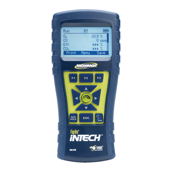
Fyrite InTech Manual Overview 1.4. Product Overview The Fyrite InTech is a portable hand-held combustion analyzer for use in residential and light commercial applications. It is intended to be used by: • HVAC contractors • home inspectors •... - Page 10 Overview Fyrite InTech Manual Feature North American (NA) versus Siegert (S) Configurations Typical North American Typical Countries (NA) Users Siegert (S) Users Asia Belgium Australia Denmark Latin America France North America Germany South America Italy Netherlands Poland Spain United Kingdom For combustion calculations, Siegert uses the fuel’s lower Heating Values...
-
Page 11: Components
Fyrite InTech Manual Overview 1.6. Components 0024-9486 Rev 2... - Page 12 Overview Fyrite InTech Manual 0024-9486 Rev 2...
-
Page 13: Features
Fyrite InTech Manual Overview 1.7. Features • Sensors (pp 51, 60) Field-replaceable electrochemical sensors (O and B-SMART Flue gas temperature measurement using a Type K thermocouple • Fuel codes (p 19) Six available fuels (in North American configuration) Ten available fuels (in Siegert configuration) •... -
Page 14: Combustion Test Process Overview
Overview Fyrite InTech Manual 1.8. Combustion Test Process Overview FUNCTION ..........PAGES Connect Probe ............13 Turn On Instrument ........14, 15, 16 Verify Power ............15 Zero Instrument (Auto/Manual) ....17, 32, 56 Use Menu System ..........17 Set System Parameters ........ -
Page 15: Fyrite Intech Sales Combinations
Fyrite InTech Manual Overview NOTE: The North American (NA) configuration of Fyrite InTech computes and displays the calculations as long as the measured oxygen is not above 16% O and the stack temperature is not above ... - Page 16 Overview Fyrite InTech Manual 0024-9486 Rev 2...
-
Page 17: Specifications
Fyrite InTech Manual Overview 1.10. Specifications Specification Description Temperature Storage: -20° to 50° C ( -4° to 122° F) 0° to 20° C (32° to 68° F ) optimal Operation: -5° to 45° C (23° to 113° F) Reference: 20°... - Page 18 Overview Fyrite InTech Manual Specification Description Power Supply Type: Disposable Alkaline (Included) Options Duration: 15 hours min, continuous max draw Type: Disposable Lithium Batteries (4 AA) Duration: 20 hours, continuous max draw Type: Rechargeable Duration: 8 hours, continuous max draw Response Measure Range...
-
Page 19: Setup
Fyrite InTech Manual Setup Section 2. Setup 2.1. Connecting the Probe and Thermocouple A rigid stainless steel probe with handle is connected to a flexible hose with an integral water-trap/filter used to draw a gas sample into the analyzer from the room, grilles, diffusers, and furnace flues. -
Page 20: Front Panel Buttons
Setup Fyrite InTech Manual 2.2. Front Panel Buttons Button Description • Powers the analyzer ON and OFF. Hold this button down for at least 2 seconds to turn the power OFF. Toggles the backlight ON and OFF while the analyzer is •... -
Page 21: Power Options
Fyrite InTech Manual Setup 2.3. Power Options You use the PWR button to turn on the Fyrite InTech . Power options include: • Disposable AA alkaline batteries (included) • Disposable AA lithium (Li) batteries • Externally charged rechargeable NiMH batteries. ... -
Page 22: Turning On The Fyrite Intech
Setup Fyrite InTech Manual NOTE: A Set Clock error message will be displayed if the instrument is without power for an extended period of time. 2.4. Turning On the Fyrite InTech To turn on the Fyrite InTech , press the PWR button. -
Page 23: Configuration
3.2. The Warm-up Sequence Boot Screens Description Splash screen shows the Bacharach logo with version, model number, and serial number information. This screen is displayed for approximately 3 seconds. A warm-up screen is displayed during which the instrument is purged and initialized. -
Page 24: Main Menu
Configuration Fyrite InTech Manual 3.3. Main Menu Display the Main Menu by pressing the F2 key. Note that features and items displayed in menus are model dependent. Your screens may vary. Main Menu Function Access the Select Fuel Menu (see page 19) •... -
Page 25: Select Fuel Menu
Fyrite InTech Manual Configuration 3.4. Select Fuel Menu Select Fuel Function Select the combustion fuel from the fuel list. Use the ) and DOWN ) UP ( arrow keys to highlight the desired fuel and use the ENTER key to select. NA Fuel List Siegert Fuel List Natural Gas... -
Page 26: Ambient Co Menu (Siegert Only)
Configuration Fyrite InTech Manual 3.5. Ambient CO Menu (Siegert Only) Ambient CO Function Access the Ambient CO Menu (Siegert only). When initiated, the Ambient CO feature monitors CO values continuously and captures a reading every minute for 15 minutes (a total of 16 readings from t to t Press ENTER to initiate the Ambient CO test. - Page 27 Fyrite InTech Manual Configuration Ambient CO Function The test results can be printed by pressing F1 and saved to memory (with a time and date stamp) by pressing F3. Press F2 to return to the menu. NOTE: If the ambient CO results are saved to memory, they are not included as part of the Print Average feature.
-
Page 28: Memory Options Menu
Configuration Fyrite InTech Manual 3.6. Memory Options Menu Memory Options Function Access the Memory Directory. This directory contains a numbered list of saved combustion tests (starting at “1”). “NO DATA” is displayed if no tests were saved since the last time that memory was cleared. - Page 29 Fyrite InTech Manual Configuration Memory Options Function Print Average (Siegert Only) displays the memory directory with the first 3 samples highlighted. Use the UP () and DOWN () arrow buttons to move the scrolling window up and down to select which three contiguous samples are to be averaged, then press ENTER.
-
Page 30: Setup Menu
Configuration Fyrite InTech Manual 3.7. Setup Menu Setup Menu Function Access Temperature Units (°C or °F) to be used by the instrument and for display and printing purposes. ) and ) Use the UP ( DOWN ( arrows buttons to highlight the desired choice. - Page 31 Fyrite InTech Manual Configuration Setup Menu Function WARNING: DO NOT use the Fyrite InTech to sample gas from an oil-based combustion system without first doing a smoke test and adjusting your combustion process as needed. Smoke test results of greater than indicate...
- Page 32 Configuration Fyrite InTech Manual Setup Menu Function A boiler temperature (Siegert only) can be recorded manually. Enter the boiler temperature as measured by an external thermocouple. Use the LEFT () and RIGHT () arrow buttons to change position. Use the UP () and DOWN () arrow buttons to scroll through numerals 0-9 for the selected position.
- Page 33 Fyrite InTech Manual Configuration Setup Menu Function NOTE: The presence of AM or PM after the time on the Set Clock display indicates 12-hour time format and MM/DD/YY date format. (This also indicates that the instrument must be in the North American configuration.) Similarly, the absence of AM or PM indicates 24-hour time format and the...
- Page 34 Configuration Fyrite InTech Manual Setup Menu Function Provides an interface for entering user identification information used on printouts. Generally, the Username fields contain the HVAC company and related information. NOTE: This data can be entered using the Fyrite User Software (FUS).
- Page 35 Fyrite InTech Manual Configuration Setup Menu Function The Language Selection option allows the user to choose a language for all menus. Use the UP () and DOWN () arrow buttons to scroll through language options (varies based on instrument model). ENTER to enable the selected language.
- Page 36 Configuration Fyrite InTech Manual Setup Menu Function Provides a list from which to select an inactivity (key press) timeout for automatic shutdown. If no key presses occur for the time specified, the Fyrite InTech initiates an automatic shutdown. Use the UP () and DOWN () arrow buttons to scroll never [default], through Inactivity Timeout options (...
- Page 37 Fyrite InTech Manual Configuration Setup Menu Function Date format (North American Configuration only) Provides a list from which the user may select the desired date format used by the instrument: • MM/DD/YY (default for NA configurations) • DD/MM/YY (standard for Siegert) NOTE: The DD/MM/YY date format is the only format available in instruments configured...
- Page 38 Configuration Fyrite InTech Manual Setup Menu Function Provides a list from which the user may select the desired method for zeroing the CO sensor. • Auto-Zero happens automatically at warm-up. • Manual zero is used to initiate the zeroing process whenever desired.
- Page 39 Fyrite InTech Manual Configuration Setup Menu Function IMPORTANT: Changing this setting resets several configuration parameters to their default values. Below is a list of affected parameters, and those unaffected. Reset to Unchanged Default Values Temperature units Manual/Auto zero (Oxygen) reference Calibration data Fuel...
-
Page 40: Calibration Menu
Configuration Fyrite InTech Manual 3.8. Calibration Menu Calibration Menu Function Calibration is performed by applying known values and accessing the password-protected menu items. When the Calibration Menu is selected, the user must enter a 4-digit numeric security code in order to proceed to the calibration options. -
Page 41: Diagnostics Menu
Fyrite InTech Manual Configuration 3.9. Diagnostics Menu Diagnostics Menu Function Displays time metrics for pump use and total operation time. Displays information about the measurement sensors of the instrument. Displays the estimated oxygen (O ) sensor life based •... - Page 42 Configuration Fyrite InTech Manual Diagnostics Menu Function In this case: • Note the 3-digit date code on the new sensor • Replace the O sensor • Press F3 to change and verify sensor date code. Resetting the Sensor Date Code Use the LEFT () and RIGHT () arrow buttons to move the cursor horizontally to select between the 2-digit month code (00-12) and the one digit year code...
-
Page 43: Status Menu
Fyrite InTech Manual Configuration Diagnostics Menu Function NOTE: If either of the entered values is incorrect, the status of your O sensor life will not be accurate. Actual sensor life may vary. Displays fresh air diagnostics similar to the display at warm-up. -
Page 44: Operation
Fyrite InTech Manual Operation Section 4. Operation 4.1. Prerequisites Before beginning your combustion test, verify the following: • menu items are properly configured • the water trap is empty, filter is clean, and arrow is pointing UP • the probe and thermocouple are attached to the instrument •... - Page 45 Fyrite InTech Manual Operation Example Forced Air Furnace Example Hot Water Tank For atmospheric burner or gravity Domestic hot water tanks with the ‘bell’ vented, forced air heating equipment shaped draft diverter can be accurately with a clamshell or sectional heat tested by inserting the probe tip directly exchanger design, test each of the into the top of the fire tube below the...
- Page 46 Operation Fyrite InTech Manual Example 80% Efficiency Example Example 90% Efficiency Fan Assist or Power Atmospheric/Gravity Condensing Furnace Vented Furnace Vented Boiler Condensing furnaces/ Combustion testing of fan Boilers, which have a ‘bell’ boilers can be tested assist or power vented, shaped draft diverter on through a hole drilled in furnaces/boilers...
-
Page 47: Combustion Testing Process
Fyrite InTech Manual Operation 4.3. Combustion Testing Process WARNING: The Fyrite InTech calculates combustion parameters based on North American or Siegert combustion equations. NA or Siegert configuration is selected in the SETUP MENU. Be sure that ... -
Page 48: The Run Screen
Operation Fyrite InTech Manual Step Example Combustion Testing Procedure purge component that clears the sensors of combustion gases. Turn on the instrument to optionally print and/or evaluate saved test results (based on your local codes and practices for combustion data and CO levels). -
Page 49: Printing Using The Optional Irda Printer
Fyrite InTech Manual Operation Combustion Test Parameters Siegert Oxygen O₂ O₂ Carbon Monoxide Excess Air Lambda Efficiency Using Higher Heating Value Carbon Dioxide CO₂ CO₂ Setting for Maximum Carbon Dioxide in Flue Gas CO₂ Max Stack Temperature T-STK T-STK Ambient Air Temperature T-AIR... - Page 50 Operation Fyrite InTech Manual Combustion Equations are shown below. Fyrite InTech provides three lines of 20 characters for user information. This information will appear with test records when they are printed. User name and optional information are entered via software menu selections in the ...
- Page 51 Fyrite InTech Manual Operation IR Communications Settings: Baud Rate: 9600 Data Bits: Stop Bits: Parity: None Protocol: IRDA-SIR Distance: 8-16 in (20-41 cm) Angle: 60° maximum 0024-9486 Rev 2...
-
Page 52: Instruction
Operation Fyrite InTech Manual Fyrite InTech can be setup to include a custom logo on printouts. Logos are loaded into the instrument using the Fyrite User Software (FUS). Logo size is limited to 192 x 384 pixels (height x width) and must be in one of the following formats: .BMP, .JPG, .PNG, or .TIFF. -
Page 53: Pc Interface And Fyrite User Software
Fyrite InTech Manual Operation 4.7. PC Interface and Fyrite User Software A PC with Fyrite User Software (FUS) installed can set, edit, and transfer the following: • instrument time and date • calibration password • time meters ... -
Page 54: Calibration And Maintenance
Fyrite InTech Manual Calibration and Maintenance Section 5. Calibration and Maintenance 5.1. Serviceability The instrument operator is able to easily replace the following components without the use of tools: • probe assembly • probe filters • batteries • printer paper. -
Page 55: Equipment Required
Fyrite InTech Manual Calibration and Maintenance 5.2.1. Equipment Required • Alcohol • Aerosol Can of Automotive Carburetor Cleaner • Clean Rag • Source of Compressed Air (optional) CAUTION: Do not use flammable or combustible substances (like carburetor fluid used for cleaning the probe) near an open flame. 5.2.2. -
Page 56: Water Trap And Filter Replacement
Calibration and Maintenance Fyrite InTech Manual 5.3. Water Trap and Filter Replacement 0024-9486 Rev 2... -
Page 57: O 2 And/Or Co Sensor Replacement
Fyrite InTech Manual Calibration and Maintenance 5.4. O and/or CO Sensor Replacement NOTE: The O sensor life is approximately 2 years. The CO sensor life is greater than 3 years. 5.4.1. Accessing the Sensors 5.4.2. Material Required (As Needed) •... -
Page 58: Sensor Replacement Procedure
Calibration and Maintenance Fyrite InTech Manual 5.4.3. O Sensor Replacement Procedure Follow the procedure below for O sensors. Step Sensor Replacement Remove battery door and connector tubing from both sensors. Pull O sensor from its socket. Remove the O cap. -
Page 59: B-Smart Co Sensor Replacement
CALIBRATION MENU. If an incorrect code was entered, the screen will display "Invalid Code." Check to make sure the correct code has been entered. If problem persists, contact your nearest Bacharach Service Provider. NOTE: B-SMART codes can be entered through the Fyrite User Software (FUS). -
Page 60: T-Stack Calibration
Calibration and Maintenance Fyrite InTech Manual NOTE: Bacharach offers a convenient Exchange Program (where available) that allows the customer to regularly receive pre-calibrated replacement sensors that include a code that can be entered into the analyzer for a quick convenient setup. - Page 61 Fyrite InTech Manual Calibration and Maintenance Step T-STACK Calibration Procedure "Measured" is the current temperature reading. "Applied" is a known temperature that will be applied for calibration purposes. Set thermocouple simulator to 32° F (0° C), and then use the UP (), DOWN (), LEFT (), and RIGHT () arrow buttons to enter an Applied value that exactly equals the setting of the simulator.
-
Page 62: Co Sensor Calibration
Calibration and Maintenance Fyrite InTech Manual Step T-STACK Calibration Procedure Wait until the Measured reading stabilizes, and then press ENTER to calibrate the TS-Span Measured value to that of the “Applied” value, after which the message “Good Calibration” should briefly appear followed by the CALIBRATION menu being re-displayed. -
Page 63: Co Sensor Span Procedure
Applied value that exactly equals the concentration stamped on the CO cylinder. NOTE: Bacharach recommends using a 500 ppm calibration gas, however the calibration range is from 20 to 1,000 ppm. An attempt to calibrate outside this range will cause the message “Applied Value High”... -
Page 64: T-Ref Sensor Calibration
Calibration and Maintenance Fyrite InTech Manual 5.7. T-Ref Sensor Calibration The T-Ref sensor is located inside the instrument. Calibration is done at the factory and should not need to be done in the field. ∇ ∇ ∇ 0024-9486 Rev 2... -
Page 65: Troubleshooting
Fyrite InTech Manual Troubleshooting Section 6. Troubleshooting 6.1. Error and Warning Messages Message Description T-STK The probe thermocouple is not connected to the analyzers T-Stack connector. Plug the probe thermocouple plug into the T-Stack connector at the bottom of the instrument. Check Sensor sensor output is low, but still usable. -
Page 66: Replacement Parts
Troubleshooting Fyrite InTech Manual Message Description instrument. • Messages will indicate which sensors are in error. Set Clock Time and date values need to be set in the instrument. If a “set clock” message occurs, then NOTE: instrument ignores –related messages except “Bad Sensor.”... -
Page 67: Accessories
Fyrite InTech Manual Troubleshooting Part Number Description 0024-1484 CO Sensor Cap 0024-1458 CO Sensor Base 0024-9486 Instruction manual 0019-3265 Water trap 6.3. Accessories Part Number Optional Accessory 0024-1400 IrDA printer 0024-1310 Printer paper, box of 5 rolls 0021-7006 Smoke kit 0104-1798 Thermocouple (temperature, air), K type (1 inch long) -
Page 68: Instrument Identification
North American Label Siegert Label 6.5. Service Centers Replacement parts and service can be obtained by contacting one of the following Bacharach Service Centers. Canada United States Bacharach of Canada, Inc. Bacharach, Inc. 20 Amber Street Unit #7... -
Page 69: Declaration Of Conformity
Apparatus Used in Non-Statutory Servicing of Gas-Fired Heating Appliances Signature: Name: Doug Keeports Title: VP of Product Development Date: November 12, 2012 The technical documentation file required by this directive is maintained at the corporate headquarters of Bacharach, Inc. 0024-9486 Rev 2... - Page 70 Declaration of Conformity Fyrite InTech Manual 0024-9486 Rev 2...
- Page 71 Fyrite InTech Manual 0024-9486 Rev 2...
- Page 72 Fyrite InTech Manual World Headquarters 621 Hunt Valley Circle, New Kensington, Pennsylvania 15068 Phone: 724-334-5000 • Toll Free: 1-800-736-4666 • Fax: 724-334-5001 Website: www.MyBacharach.com • E-mail: help@MyBacharach.com 0024-9486 Rev 2...
Need help?
Do you have a question about the Fyrite INTECH and is the answer not in the manual?
Questions and answers