Table of Contents
Advertisement
Quick Links
Quick Start Guide
EDID MANAGER V4
Important safety instructions
Please read and keep the information in the attached safety instructions supplied with the
product before you start using the device.
Introduction
Thank You for choosing Lightware EDID MANAGER V4, our HDCP compatible HDMI/DVI
EDID Emulator and cable extender with USB control. The device can store 79 EDIDs. It
emulates and keeps a fixed EDID for the source. Thanks to our Advanced EDID Management,
the device can trick the source (PC computer, laptop, etc.) by emulating any DVI/HDMI display
(LCD monitor, projector) for continuous video output - even if the AV system is disconnected or
powered down. With EDID emulation, the user can set up any DVI or HDMI output resolution,
regardless of the used projector or monitor. This ensures that the overall system resolution can
be controlled. There are 49 factory and 29 user programmable presets available, and the last
attached display device's EDID is also stored separately on address 00#, to be able to clone
it to the input (clone mode).
Box Contents
EDID MANAGER V4 unit
5V DC adaptor with
Safety and warranty info,
interchangeable plugs
Quick Start Guide
Features
ƒ Advanced EDID Management – The user can emulate any EDID on the device's input
by using the 49 factory or 29 user presets. Any attached monitor's EDID can be read out,
edited and stored as user presets by the Lightware Device Controller Software.
ƒ HDCP Management – HDCP communication between source and display devices can
be permitted or prohibited by the unit. Lightware is a legal HDCP adopter.
ƒ 60 meter input cable compensation – Using 22AWG high quality DVI cable, the input
is automatically compensated for up to 60 meter cable length, which extends installation
possibilities even on highest HDTV or computer resolutions. In case of lower pixel
resolutions, this length can be even higher.
ƒ Top panel control – EDID address selection with two decimal rotary switches, Learn
EDID and Burn EDID buttons are available for Advanced EDID Management.
ƒ USB control – The EDID Manager V4 is controllable via the Lightware Device Controller
software where Advanced EDID Management is available. Firmware upgrade can also
be performed over this interface.
ƒ Supports all HDTV resolutions – Supports HDCP encrypted and unencrypted HDTV
signals up to 225 MHz pixel clock frequency regardless of the resolution being passed
through. (720p, 1080i and 1080p etc.)
ƒ Fiber cable support – Self-powered DVI fiber cables using +5V from DVI sources
(VGA cards, etc.) usually consumes more than 50 mA (maximum suggested by DVI 1.0
standard). Lightware devices support +5V 500 mA constant current output on the DVI
outputs to power long distance fiber optical cables.
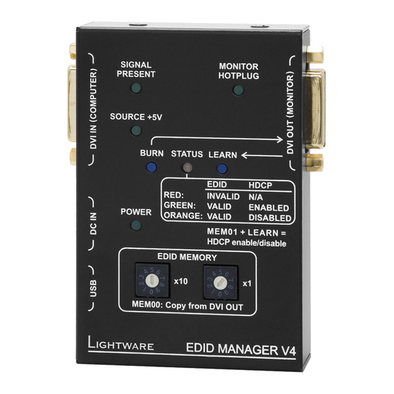
Top View
1
2
3
4
5
6
7
8
9
Locking DC Plug
Twist 90° clockwise to lock.
DVI Connectors
DVI Input
The input has a built-in signal detection circuit with a LED indicator. The Signal Present LED
lights green, if the INPUT connector senses an active DVI/HDMI signal.
DVI Output
Monitor hotplug is detected on the output port (Monitor Hotplug LED lights green). After a
hotplug event, the EDID Manager V4 tries to read the EDID of the connected device. No output
reclocking is provided. If a long DVI cable is connected then equalization and reclocking may
be necessary at the receiver end of the cable.
Fiber Cable Powering
As a special feature, the device is able to supply 500 mA current on DDC +5V output (pin 14 on
output connector) to power fiber optical DVI transmitters. Standard DVI outputs or VGA cards
supply only 55 mA current on +5V output, thus unable to power directly a fiber optical cable.
Appliable Cable Length
Maximum 60 meters 22AWG DVI cable is recommended for 1080p (Full HD) resolution on
the input.
Specification
General
Compliance ...............................................................................................................CE
EMI / EMC .................................................................................. EN 55024 / EN 55032
Safety ..................................................................................................................Class II
Warranty ............................................................................................................. 3 years
Cooling .............................................................................................................. passive
Power consumption ....................................................................................... 2 W (max)
Operating temperature ....................................................... 0 to +50˚C (+32 to +122˚F)
Operating humidity ......................................................... 10% to 90%, non-condensing
Enclosure
DC power connector .............................................. locking DC connector, 2.5 / 5.5 mm
Material ......................................................................................................... 1 mm steel
Dimensions ..................100.4 W x 67.6 D x 26 H mm (3.95 W x 2.66 D x 1.02 H inch)
Weight .................................................................................................225 g (0.496 lbs)
Rack mountable ......................................................................................................... No
Supplied Power Adaptor
Input ............................................................................. AC 100-240 V, 50~60 Hz, 0.6 A
Output ........................................................................................................ DC 5V, 2.6 A
1
Status LED
LED gives feedback about the current status of the device.
ON - GREEN: EDID and HDCP status indicator: if the selected
EDID is valid and HDCP is enabled the LED lights green.
ON - ORANGE: EDID and HDCP status indicator: if the selected
EDID is valid and HDCP is disabled the LED lights orange.
ON - RED: EDID status indicator: if the selected EDID is invalid
e
the LED lights red.
w
BLINKING - GREEN: EDID status indicator: Burn / Learn
process or reading connected device's EDID was successful.
BLINKING - RED: EDID status indicatior: Burn / Learn process
q
or reading connected device's EDID failed.
BLINKING - RED/GREEN: Firmware upgrade status indicator:
during firmware upgrade the LED flashes red and green.
2
Signal
Indicates if a valid DVI / HDMI clock signal is present on the DVI
Present LED
IN connector.
3
DVI IN
DVI-I input connector for DVI-D / HDMI signal.
connector
4
Source +5V
Indicates if 5V power signal is sent to pin 14 of the input DVI
LED
connector by the DVI source (PC, Laptop, etc.).
Pinout of the DVI-I Connector
1
2
3
4
5
6
7
8
9 10 11
12 13
14 15
16
17 18 19
20 21
22 23
24
Pin
Signal
Pin
Signal
1
TMDS Data2-
9
TMDS Data1-
2
TMDS Data2+
10
TMDS Data1+
3
TMDS Data2 Shield
11
TMDS Data1 Shield
4
Not connected
12
Not connected
5
Not connected
13
Not connected
6
DDC Clock
14
+5V Power
7
DDC Data
15
GND (for +5V)
8
Not connected
16
Hot Plug Detect
C1
Not connected
C2
Not connected
C4
Not connected
C5
GND
Input
Connector ............................................................................... 29-pole DVI-I digital only
Input cable equalization ...................................................................... Yes, +40 dB max
EDID emulation......................................................................................................... Yes
HDCP compliant ....................................................................................................... Yes
Output
Connector ............................................................................... 29 pole DVI-I digital only
Reclocking ................................................................................................................. No
+5V output current ..............................................................................................500 mA
Signal
Data rate ................................. all between 250 Mbps and 2.25 Gbps / TMDS channel
Channels .................................................................1x TMDS Clock + 3x TMDS Colors
Resolutions ............................................all between 640x480 and 1920x1200@60Hz,
..................................................................................................... or 2048x1080@60Hz
Color depth ..................................................................... maximum 36 bits, 12 bit/color
Color space ................................................................................................ RGB, YCbCr
HDTV resolutions ............................................................................720p, 1080i, 1080p
HDMI 1.3a compatible ........................................................Yes (with embedded audio)
HDCP compliant ....................................................................................................... Yes
5
Burn button
Reprograms the attached device's input EDID data (legacy
purpose). Attention: burning a wrong EDID can damage the display!
6
DC input
Locking 5V DC power input connector, center pin positive.
connector
Protected from polarity exchange.
7
Power LED
The LED indicates the presence of proper power supply voltage.
8
USB
USB interface for LDC connection (Advanced EDID
connector
management) and firmware upgrade.
9
EDID Rotary
The rotary switches select one of the EDID memory addresses.
switches
Addresses 01#..49# are factory presets and 51#..79# are user
programmable presets. Address 00# enables transparent mode.
Address 01# is also used for HDCP status change.
q
Learn button
Stores the EDID of the display device attached to DVI OUT in
the selected memory address between 51#..79#. To learn the
EDID, select an appropriate address with the rotary switches
and press and hold the Learn button for two seconds.
w
DVI OUT
DVI-I output connector for DVI-D / HDMI signal.
connector
e
Monitor
Indicates if a powered display device (or matrix switcher,
Hotplug LED
repeater, etc.) is connected to the DVI output connector and
sends a valid hotplug signal on pin 16 through the DVI cable.
Connecting Steps
PC
Projector
C1 C2
C3 C4
C5
DVI
DVI
Pin
Signal
17
TMDS Data0-
EDID
18
TMDS Data0+
MANAGER
V4
19
TMDS Data0 Shield
20
Not connected
Power
USB
21
Not connected
22
TMDS Clock Shield
23
TMDS Clock+
24
TMDS Clock-
Power adaptor
Laptop
C3
Not connected
The document is valid with the following firmware version: 1.2.3
The product brief and further information are available at www.lightware.eu.
See the
Downloads
Lightware Visual Engineering LLC.
Peterdy 15, Budapest H-1071, Hungary
DVI
Connect the EDID Manager
V4 and the source device (e.g.
PC) using a DVI cable.
DVI
Connect the EDID Manager
V4 and the sink device (e.g.
projector) using a DVI cable.
USB
Optionally connect a controller
device (e.g. laptop) to the USB
port of the device.
Power
Firstly connect the power
adaptor to the DC input on the
device, then to the AC power
socket.
Powering on the devices is recommended to
do as the final step during the installation.
Further information
section on the website of the product.
Contact us
sales@lightware.eu
+36 1 255 3800
support@lightware.eu
+36 1 255 3810
Doc. ver.: 2.1
19200051
Advertisement
Table of Contents

Subscribe to Our Youtube Channel
Related Manuals for Lightware EDID MANAGER V4


Summary of Contents for Lightware EDID MANAGER V4
-
Page 1: Quick Start Guide
EDID is also stored separately on address 00#, to be able to clone Power Firstly connect the power hotplug event, the EDID Manager V4 tries to read the EDID of the connected device. No output Not connected Not connected Not connected it to the input (clone mode). - Page 2 Lightware Device Controller. Please download the application from ƒ Check the device - Check whether the EDID Manager V4 is properly powered and the Power www.lightware.eu, install on a Windows PC or a Mac OS X and connect to creation.
Need help?
Do you have a question about the EDID MANAGER V4 and is the answer not in the manual?
Questions and answers