DURKOPP ADLER 610-10 Operating Instructions Manual
Hide thumbs
Also See for 610-10:
- Service instructions manual (152 pages) ,
- Additional instructions (14 pages)
Table of Contents
Advertisement
Quick Links
Advertisement
Table of Contents

Related Manuals for DURKOPP ADLER 610-10


Summary of Contents for DURKOPP ADLER 610-10
- Page 1 610-10/630-10 Operating Instructions...
- Page 2 IMPORTANT READ CAREFULLY BEFORE USE KEEP FOR FUTURE REFERENCE All rights reserved. Property of Dürkopp Adler GmbH and protected by copyright. Any reuse of these contents, including extracts, is prohibited without the prior written approval of Dürkopp Adler GmbH. Copyright © Dürkopp Adler GmbH 2021...
-
Page 3: Table Of Contents
Input of numeric values ............... 44 5.1.2 Inputting text ..................46 Controller operating modes ..............48 Operating mode MAN................49 5.3.1 Parameters that can be set ..............50 5.3.2 Sewing process ................... 53 Operating mode AUTO................ 54 Operating Instructions 610-10/630-10 - 01.0 - 01/2021... - Page 4 Setting operating pressure ..............106 Carrying out a test run ............... 108 Decommissioning ................109 Packing, transportation ..............111 Disposal ................... 113 Troubleshooting ................115 11.1 Customer Service ................115 11.2 Messages of the software ..............115 Operating Instructions 610-10/630-10 - 01.0 - 01/2021...
- Page 5 Table of Contents Errors in sewing process ..............132 11.3 Technical data ................. 135 Appendix ..................137 Operating Instructions 610-10/630-10 - 01.0 - 01/2021...
- Page 6 Table of Contents Operating Instructions 610-10/630-10 - 01.0 - 01/2021...
-
Page 7: About These Instructions
Representation conventions – symbols and characters Various information in these instructions is represented or high- lighted by the following characters in order to facilitate easy and quick understanding: Proper setting Specifies proper setting. Operating Instructions 610-10/630-10 - 01.0 - 01/2021... - Page 8 Important Special attention must be paid to this point when performing a step. Information Additional information, e.g. on alternative operating options. Order Specifies the work to be performed before or after a setting. Operating Instructions 610-10/630-10 - 01.0 - 01/2021...
-
Page 9: Other Documents
Dürkopp Adler cannot be held liable for any damage resulting from: • Breakage and damage during transport • Failure to observe these instructions • Improper use • Unauthorized modifications to the machine • Use of untrained personnel • Use of unapproved parts Operating Instructions 610-10/630-10 - 01.0 - 01/2021... - Page 10 Leave machines, equipment and packaging material in the con- dition in which they were found when the damage was discovered. This will ensure any claims against the transport company. Report all other complaints to Dürkopp Adler immediately after receiving the product. Operating Instructions 610-10/630-10 - 01.0 - 01/2021...
-
Page 11: Safety
Obligations Follow the country-specific safety and accident prevention regu- of the operator lations and the legal regulations concerning industrial safety and the protection of the environment. Operating Instructions 610-10/630-10 - 01.0 - 01/2021... -
Page 12: Signal Words And Symbols Used In Warnings
Signal words Signal words and the hazard they describe: Signal word Meaning DANGER (with hazard symbol) If ignored, fatal or serious injury will result WARNING (with hazard symbol) If ignored, fatal or serious injury can result Operating Instructions 610-10/630-10 - 01.0 - 01/2021... - Page 13 If ignored, environmental damage can result NOTICE (without hazard symbol) If ignored, property damage can result Symbols The following symbols indicate the type of danger to personnel: Symbol Type of danger General Electric shock Puncture Crushing Environmental damage Operating Instructions 610-10/630-10 - 01.0 - 01/2021...
- Page 14 Type and source of danger! Consequences of non-compliance. Measures for avoiding the danger. This is what a warning looks like for a hazard that could result in moderate or minor injury if the warning is ignored. Operating Instructions 610-10/630-10 - 01.0 - 01/2021...
- Page 15 CAUTION Type and source of danger! Consequences of non-compliance. Measures for avoiding the danger. This is what a warning looks like for a hazard that could result in environmental damage if ignored. Operating Instructions 610-10/630-10 - 01.0 - 01/2021...
- Page 16 Safety Operating Instructions 610-10/630-10 - 01.0 - 01/2021...
-
Page 17: Machine Description
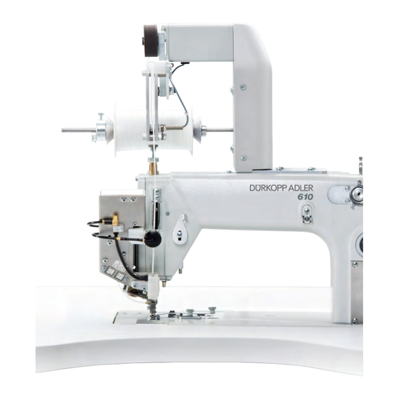
④ ④ ⑤ (1) - Tape unwinder (5) - Knee button (2) - Machine head (6) - Controller (3) - Stand (7) - Control panel (4) - Pedal (8) - Thread reel holder Operating Instructions 610-10/630-10 - 01.0 - 01/2021... -
Page 18: Declaration Of Conformity
The machine may only be set up and operated in dry conditions on well-maintained premises. If the machine is operated on premises that are not dry and well-maintained, then further measures may be required which must be compatible with DIN EN 60204-31. Operating Instructions 610-10/630-10 - 01.0 - 01/2021... - Page 19 Machine description Only authorized persons may work on the machine. Dürkopp Adler cannot be held liable for damages resulting from improper use. Operating Instructions 610-10/630-10 - 01.0 - 01/2021...
- Page 20 Improper use can result in electric shock, crushing, cutting and punctures. Follow all instructions provided. NOTICE Property damage from non-observance! Improper use can result in material damage at the machine. Follow all instructions provided. Operating Instructions 610-10/630-10 - 01.0 - 01/2021...
-
Page 21: Operation
Complete the following steps in preparation of sewing before starting to work: • Changing the needle • Threading the needle thread • Threading the looper thread • Threading the reinforcement tape (610-10 only) • Adjusting the thread tension Operating Instructions 610-10/630-10 - 01.0 - 01/2021... -
Page 22: Switching On And Off The Machine
Once the pneumatic connection ( p. 105) has been established, the machine can be switched on and off using the main switch on the controller. Fig. 2: Switching on and off the machine ① (1) - Main switch Operating Instructions 610-10/630-10 - 01.0 - 01/2021... -
Page 23: Changing The Needle
After switching to needles with a thickness of 100 or greater, have the needle evasive movement of the looper (ellipsis width) adjust- ed by qualified specialists. For the proper setting, refer to the Service Instructions. Operating Instructions 610-10/630-10 - 01.0 - 01/2021... - Page 24 3. Pull the needle out towards the bottom. 4. Insert the new needle. Important Align the needle in such a way that the groove (2) is pointing to the rear. 5. Tighten the screw (3). Operating Instructions 610-10/630-10 - 01.0 - 01/2021...
-
Page 25: Threading The Needle Thread
2. Feed the thread from the front to the rear through the 1 hole on the front. Feed the thread from the rear to the front through the next hole. Important The thread guide (1) must be positioned vertically above the thread reel holder (2). Operating Instructions 610-10/630-10 - 01.0 - 01/2021... - Page 26 (11). 9. Feed the thread from the right to the left through the diverter (3). 10. Feed the thread from right to left through the thread regulator (4) and the thread lever (5): Operating Instructions 610-10/630-10 - 01.0 - 01/2021...
-
Page 27: Threading The Looper Thread
Fig. 7: Threading the looper thread (1) ① ② (1) - Thread guide (2) - Thread reel holder To thread the looper thread: 1. Slip the thread reel onto the right plate of the thread reel holder (2). Operating Instructions 610-10/630-10 - 01.0 - 01/2021... - Page 28 ⑧ ⑦ ⑥ ⑤ ③ ④ (3) - Thread channel (6) - Looper thread tensioner element (4) - Thread advancing device (7) - Thread guide (5) - Thread guide (8) - Thread guide Operating Instructions 610-10/630-10 - 01.0 - 01/2021...
- Page 29 11. Turn the handwheel to position D in such a way that the thread take-up disk (11) is adjusted accordingly. 12. Insert the thread from the right to the left through the holes (12) of the looper thread guide. Operating Instructions 610-10/630-10 - 01.0 - 01/2021...
-
Page 30: Threading The Reinforcement Tape (610-10 Only)
Facing the head cover, the reel of reinforcement tape must rotate clockwise when unwinding. Fig. 11: Threading the reinforcement tape (1) ① ② ③ (1) - Reel of reinforcement tape (3) - Counter bearing (2) - Reel holder Operating Instructions 610-10/630-10 - 01.0 - 01/2021... - Page 31 2. Insert the reinforcement tape through the guide (4). 3. Feed the tape between transport roller (5) and spring-loaded pressure roller (8). 4. Feed the tape through underneath the sensor transducer (6). 5. Insert the reinforcement tape through the guide (7). Operating Instructions 610-10/630-10 - 01.0 - 01/2021...
- Page 32 (11) and the guide piece (10). Grab the reinforcement tape, using, for example, a pair of twee- zers while holding on to the end. Operating Instructions 610-10/630-10 - 01.0 - 01/2021...
-
Page 33: Adjusting Thread Tension And Thread Quantity For The Seam Pattern
• Too tight: Crimping of the sewing material • Too loose: Missing stitches Use the control panel ( et sqq) to set the thread tension ( p. 50 f). 4.7.3 Adjusting the needle thread quantity See Service Instructions. Operating Instructions 610-10/630-10 - 01.0 - 01/2021... -
Page 34: Adjusting The Looper Thread Quantity
Disturbance from incorrectly set sewing foot pressure • Excessively high sewing foot pressure: Impressions on the sewing material, possibly ruffling of the sewing material • Excessively low sewing foot pressure: Slipping of the sewing material, stitch length too short Operating Instructions 610-10/630-10 - 01.0 - 01/2021... - Page 35 • Reduce sewing foot pressure = turn the nut (2) counter- clockwise. Important Hold the adjusting wheel (1) in place during the adjustment in order to prevent the pressure of the top feed foot from being altered inadvertently! 3. Re-tighten the nut (3). Operating Instructions 610-10/630-10 - 01.0 - 01/2021...
- Page 36 To adjust the sewing foot pressure for the top feed foot: 1. Setting the sewing foot pressure: • Increase sewing foot pressure = turn the adjusting wheel (1) clockwise • Reduce sewing foot pressure = turn the adjusting wheel (1) counterclockwise Operating Instructions 610-10/630-10 - 01.0 - 01/2021...
-
Page 37: Lifting Sewing Foot
The sewing foot is raised and remains raised while the pedal is held in position. To lift the sewing foot at the seam end: 1. Press the pedal to position -2 (4). The thread is cut, and the sewing foot is lifted. Operating Instructions 610-10/630-10 - 01.0 - 01/2021... - Page 38 (3) - Rest position cut off thread (4) - Sewing active (2) - Lift sewing foot To lower the sewing foot: 1. Press the pedal to position 0. The sewing foot lowers. Operating Instructions 610-10/630-10 - 01.0 - 01/2021...
-
Page 39: Locking The Sewing Foot In Place In Top Dead Center
2. Press the locking button. 3. Release the pedal. The sewing foot is locked in place in top dead center. You can remove the lock by lowering the sewing foot ( p. 35). Operating Instructions 610-10/630-10 - 01.0 - 01/2021... -
Page 40: 4.11 Tilting And Re-Erecting The Machine Head
Use the handle (3) to tilt the machine head (1) up to the support (2). Erecting the machine head To erect the machine head: Carefully erect the machine head (1) using the handle (3). Operating Instructions 610-10/630-10 - 01.0 - 01/2021... -
Page 41: 4.12 Switching The Sewing Lamp On And Off
(1) - Switch To switch on the sewing lamp: 1. Press switch (1) to the left to position I. To switch off the sewing lamp: 1. Press switch (1) to the right to position 0. Operating Instructions 610-10/630-10 - 01.0 - 01/2021... -
Page 42: 4.13 Sewing
The sewing foot lowers onto the sewing material. AT SEAM BEGINNING Proceed as follows to start a seam: 1. Press the pedal (4) forward. The machine sews. The speed increases the further forward the pedal is pressed. Operating Instructions 610-10/630-10 - 01.0 - 01/2021... - Page 43 Proceed as follows to end the seam: 1. Press the pedal to position -2 (1) and keep it there The thread is cut. The machine stops. Needle and sewing foot are raised. 2. Remove the sewing material. Operating Instructions 610-10/630-10 - 01.0 - 01/2021...
- Page 44 Operation Operating Instructions 610-10/630-10 - 01.0 - 01/2021...
-
Page 45: Settings Via Software
Programs can be mirrored for the other side of the sewing material. All functions and inputs are triggered by touching the screen. Numeric values for the individual parameters and text for the program names can be input in the individual operating modes. Operating Instructions 610-10/630-10 - 01.0 - 01/2021... -
Page 46: Input Of Numeric Values
• Header, consisting of: • Symbol of the selected parameter • Name of the parameter • Value range of the parameter • Symbol for exiting the user interface • Input line for the value • Keypad Operating Instructions 610-10/630-10 - 01.0 - 01/2021... - Page 47 / down. Delete numerical value position from the input line Delete the input value Exit the user interface without inputting or saving any values Save the value that was input and exit the user interface Operating Instructions 610-10/630-10 - 01.0 - 01/2021...
-
Page 48: Inputting Text
• Symbol for exiting the user interface • Input line for the text • Keypad Meaning of the buttons Symbols/buttons Meaning Input of numbers in the text Input of text Input of a hyphen Operating Instructions 610-10/630-10 - 01.0 - 01/2021... - Page 49 Exit the user interface without inputting or saving any text Input of a space Switching between upper case/lower case Delete letters or digits from the input line Save the value that was input and exit the user interface Operating Instructions 610-10/630-10 - 01.0 - 01/2021...
-
Page 50: Controller Operating Modes
You can use Edit mode to create (PROGRAMMING), modify, delete, copy (EDIT) and optimize (LENGTH CORRECTION) sewing programs. • SERVICE Service mode contains functions for use during service work. Service mode is password-protected to avoid accidentally changing the machine settings. Operating Instructions 610-10/630-10 - 01.0 - 01/2021... -
Page 51: Operating Mode Man
The gray fields above the parameter symbols show the respective current values. Right pane (4) Another user interface or another operating mode can be selected here. Operating Instructions 610-10/630-10 - 01.0 - 01/2021... -
Page 52: Parameters That Can Be Set
1. Tap the desired button. The user interface for setting the desired parameter is displayed. For some parameters the setting is more than just a numerical value. These parameters are described below. Operating Instructions 610-10/630-10 - 01.0 - 01/2021... - Page 53 3. Input the fullness using the buttons 0 to 16. Mode MAN Other program parameters A tap on the Other program parameters button will bring up an overview of all available parameters. Operating Instructions 610-10/630-10 - 01.0 - 01/2021...
- Page 54 (= 1) or off (= 0) Stitch Condensing at End Stitch condensing at seam 0 – 1 on (= 1) or off (= 0) Thread Trimmer Thread trimmer 0 – 1 on (= 1) or off (= 0) Operating Instructions 610-10/630-10 - 01.0 - 01/2021...
-
Page 55: Sewing Process
1. Press the pedal to position 0. 2. Change the desired parameter on the control panel ( p. 50). 3. Press the pedal forward again and sew. The seam will be sewn using the altered parameter value. Operating Instructions 610-10/630-10 - 01.0 - 01/2021... -
Page 56: Operating Mode Auto
The graphical representation of the entire seam, divided into the number of programmed sewing steps, is displayed here. A red bar with an arrow indicates the direction of sewing and progress of the sewn seam. Operating Instructions 610-10/630-10 - 01.0 - 01/2021... -
Page 57: Parameters That Can Be Set
Applying a % correction to the fullness val- ues of all sewing steps, p. 59 Setting the needle thread tension. If changed in AUTO operating mode, the value is permanently saved in the sewing program. Operating Instructions 610-10/630-10 - 01.0 - 01/2021... - Page 58 Mode AUTO Selecting the sewing program Fig. 29: Selecting the sewing program To select a sewing program: 1. Tap the desired sewing program. The selected sewing program is displayed in an activated control field within the line. Operating Instructions 610-10/630-10 - 01.0 - 01/2021...
- Page 59 To set the sewing material size: 1. Select the size table. 2. Tap the desired sewing material size. The user interface for AUTO operating mode is displayed. Operating Instructions 610-10/630-10 - 01.0 - 01/2021...
- Page 60 • Top and bottom (differential top and bottom feed) The fullness selected is displayed in an activated control field. Display of further buttons for inputting the fullness. The buttons 0 to 16 are available for input. Operating Instructions 610-10/630-10 - 01.0 - 01/2021...
- Page 61 + F% and - F% or the fullness correction parameter. Fig. 32: Correcting the fullness value To correct the fullness value: 1. Input the correction value for the fullness in %. Information for inputting numeric values: p. 49. Operating Instructions 610-10/630-10 - 01.0 - 01/2021...
- Page 62 A tap on the Other program parameters button will bring up an overview of all available parameters. Fig. 33: Other program parameters in operating mode AUTO Parameter Meaning Value range Thread Tension at Hook Looper thread tension 1 – 99 Operating Instructions 610-10/630-10 - 01.0 - 01/2021...
-
Page 63: Sewing Process
4. Press the pedal forward and sew the seam. The sewing progress is displayed graphically in the left pane as a red bar. Fig. 34: Sewing process The remaining sewing length per sewing step is displayed: Operating Instructions 610-10/630-10 - 01.0 - 01/2021... - Page 64 3. Press the pedal forward and sew. The seam will be sewn using the altered parameter value. Canceling sewing program 1. Press the pedal to position -2. The sewing program is canceled. Operating Instructions 610-10/630-10 - 01.0 - 01/2021...
-
Page 65: Operating Mode Edit
Header (1) Operating mode EDIT is displayed. The buttons TF on / TF off are used to switch the tape feed on / off (610-10 only) or to display if sewing takes place with or without tape. Left pane (2) The graphical representation of the entire seam, divided into the number of programmed sewing steps, is displayed here. -
Page 66: Parameters That Can Be Set
Set the sewing material size, p. 65 Other program parameters in operating mode EDIT, p. 60 Temporarily setting the fullness value until the next sewing step, p. 58 Setting the needle thread tension Operating Instructions 610-10/630-10 - 01.0 - 01/2021... - Page 67 For some parameters the setting is more than just a numerical value. These more complex parameters are described in detail below. Mode EDIT Setting the sewing material size Abb. 36: Setting the sewing material size Operating Instructions 610-10/630-10 - 01.0 - 01/2021...
- Page 68 User interface EDIT is displayed. Mode EDIT Setting the fullness in the current sewing step Fig. 37: Setting the fullness Buttons for manually inputting the fullness are displayed in the left pane. Operating Instructions 610-10/630-10 - 01.0 - 01/2021...
- Page 69 3. Input the fullness using the buttons 0 to 16. Mode EDIT Other program parameters A tap on the Other program parameters button will bring up an overview of all available parameters. Operating Instructions 610-10/630-10 - 01.0 - 01/2021...
- Page 70 1 – 99 Adjust Bottom Fullness Fullness correction -50 – 50 in % parameter bottom (%) Adjust Flat Sewing in % Flat sewing correction, 0 – 50 only when sewing without fullness (%) Operating Instructions 610-10/630-10 - 01.0 - 01/2021...
-
Page 71: Creating A New Sewing Program (Programming)
Value range Thread Tension at Hook Looper thread tension 1 – 99 Maximum Speed Maximum speed 100 – 4000 5.5.2 Creating a new sewing program (PROGRAMMING) Prerequisite: • Operating mode EDIT is displayed. Operating Instructions 610-10/630-10 - 01.0 - 01/2021... - Page 72 4. Set all parameters for the 1 sewing step. 5. Use the buttons TF on and TF off to specify if the tape feed is turned on or off during this sewing step (610-10 only). Operating Instructions 610-10/630-10 - 01.0 - 01/2021...
- Page 73 The left pane displays the 2 sewing step with its number. Fig. 41: Creating a new sewing program (2) 8. Repeat sewing step 2 until all the sewing steps have been programmed. Operating Instructions 610-10/630-10 - 01.0 - 01/2021...
- Page 74 10. If the thread was not cut after sewing, the message Cut off thread appears. The message is cleared, and the following selection window appears: Fig. 42: Creating a new sewing program, selection window Operating Instructions 610-10/630-10 - 01.0 - 01/2021...
- Page 75 Meaning Input the program name There is only one display under PROGRAMMING. A new sewing program is automatically assigned the next free program slot. Select the right or left piece to be sewn Operating Instructions 610-10/630-10 - 01.0 - 01/2021...
- Page 76 1. Tap the desired button. The user interface for setting the desired parameter is displayed. For some parameters the setting is more than just a numerical value. These more complex parameters are described in detail below. Operating Instructions 610-10/630-10 - 01.0 - 01/2021...
- Page 77 • The sizes marked in red indicate the sizes in which the sewing program was created or modified. To set the sewing material size: 1. Select the size table. 2. Tap the desired sewing material size. The PROGRAMMING user interface is displayed. Operating Instructions 610-10/630-10 - 01.0 - 01/2021...
- Page 78 • Top and bottom (differential top and bottom feed) The fullness selected is displayed in an activated control field. Display of further buttons for inputting the fullness. The buttons 0 to 16 are available for input. Operating Instructions 610-10/630-10 - 01.0 - 01/2021...
- Page 79 3. Input the fullness using the buttons 0 to 16. Mode Other program parameters PROGRAMMING A tap on the Other program parameters button will bring up an overview of all available parameters. Fig. 45: Other program parameters Operating Instructions 610-10/630-10 - 01.0 - 01/2021...
- Page 80 (% per size) Mode Other sewing step parameters PROGRAMMING A tap on the Other sewing step parameters button will bring up an overview of all available parameters. Abb. 46: Other sewing step parameters Operating Instructions 610-10/630-10 - 01.0 - 01/2021...
-
Page 81: Copying The Sewing Program
Length correction (LENGTH CORRECTION) All the sewing steps are graded with the same factor. In some cases, the preset gradation is not suitable. You can use the length correction to achieve these local adjustments. Operating Instructions 610-10/630-10 - 01.0 - 01/2021... - Page 82 3. Select the next sewing step by tapping the number of the 1 sewing step or by pressing the Knee button. The sewing progress is displayed graphically. Operating Instructions 610-10/630-10 - 01.0 - 01/2021...
-
Page 83: Displaying Software Version
The controller starts in the operating mode that was active when it was switched off - MAN or AUTO. Operating mode SERVICE More information on the contents of Service mode can be found in the Service Instructions. Operating Instructions 610-10/630-10 - 01.0 - 01/2021... - Page 84 Settings via software Operating Instructions 610-10/630-10 - 01.0 - 01/2021...
-
Page 85: Maintenance
Switch the machine off prior to any maintenance work. WARNING Risk of injury from moving parts! During maintenance work, the machine may start up unintentionally. Crushing is possible. Switch the machine off prior to any maintenance work. Operating Instructions 610-10/630-10 - 01.0 - 01/2021... -
Page 86: Cleaning
Flying particles can enter the eyes, causing injury. Wear safety goggles. Hold the compressed air gun so that the particles do not fly close to people. Make sure no particles fly into the oil sump. Operating Instructions 610-10/630-10 - 01.0 - 01/2021... -
Page 87: Lubricating
Risk of injuries from contact with oil! Oil can cause a rash if it comes into contact with skin. Avoid skin contact with oil. If oil has come into contact with your skin, wash the affected areas thoroughly. Operating Instructions 610-10/630-10 - 01.0 - 01/2021... - Page 88 • Lubricating the looper Lubrication of the machine head Fig. 49: Lubrication of the machine head ① ③ ② (1) - Filler openings (3) - Minimum level mark (2) - Maximum level mark Operating Instructions 610-10/630-10 - 01.0 - 01/2021...
- Page 89 • Flash point: 150 °C You can order the lubricating oil from our sales offices using the following part numbers: Container Part no. 250 ml 9047 000011 9047 000012 9047 000013 9047 000014 Operating Instructions 610-10/630-10 - 01.0 - 01/2021...
- Page 90 Too little or too much oil can damage the machine. Top off oil as described. Tilt the machine head ( p. 38). Check the fill level in the oil reservoir (2) of the looper drive housing. Erect the machine head again. Operating Instructions 610-10/630-10 - 01.0 - 01/2021...
-
Page 91: Servicing The Pneumatic System
The operating pressure cannot deviate by more than ± 0.5 bar. Check the operating pressure on a daily basis: You can read the operating pressure on the pressure gage (2). Operating Instructions 610-10/630-10 - 01.0 - 01/2021... -
Page 92: Draining The Water Condensation
3. Push the pressure controller (1) down. 6.3.2 Draining the water condensation NOTICE Property damage from excess water condensation! Too much water condensation can result in damage to the machine. If necessary, drain the condensation water as described. Operating Instructions 610-10/630-10 - 01.0 - 01/2021... - Page 93 Disconnect the connection hose from the compressed air supply. Unscrew the drain screw (3) completely. Allow water to drain into the collection tray. Re-tighten the drain screw (3). Connect the machine to the compressed air supply. Operating Instructions 610-10/630-10 - 01.0 - 01/2021...
-
Page 94: Cleaning The Filter Element
Drain the water condensation ( p. 92). Unscrew the water separator (2). Unscrew the filter element (1). Blow out the filter element (1) using a compressed air gun. Wash out the filter tray using benzine. Operating Instructions 610-10/630-10 - 01.0 - 01/2021... - Page 95 Maintenance Tighten the filter element (1). Tighten the water separator (2). Tighten the drain screw (3). 10. Connect the machine to the compressed air supply. Operating Instructions 610-10/630-10 - 01.0 - 01/2021...
- Page 96 Maintenance Operating Instructions 610-10/630-10 - 01.0 - 01/2021...
-
Page 97: Setup
Check that the scope of delivery is correct after taking delivery. Removing the transport locks Remove all transport locks before setting up the machine. • Wooden blocks on the machine head • Safety clips on the stand feet Operating Instructions 610-10/630-10 - 01.0 - 01/2021... -
Page 98: Assembling The Stand
Ensure that the tabletop has sufficient load-bearing capacity and strength. If you want to make your own tabletop, use the dimen- sions given in the diagram (Appendix, p. 137) as an example. Operating Instructions 610-10/630-10 - 01.0 - 01/2021... -
Page 99: Assembling The Controller
1. Use screws to mount the controller to the underside of the tabletop at positions (1) and (2). The side housing the type plate will be pointing to the left. Fig. 55: Assembling the controller ② ① (1) - Screws (2) - Screws Operating Instructions 610-10/630-10 - 01.0 - 01/2021... -
Page 100: Assembling Thread Reel Holder
2. Assemble the thread reel holder tube (1) using the included nuts (2) and washers (3). 3. Align thread reel holder and thread guide. Important The thread guide must be positioned vertically above the thread reel holder. Operating Instructions 610-10/630-10 - 01.0 - 01/2021... - Page 101 Fig. 57: Assembling the thread reel holder (tabletop upper side) ① ② ③ (1) - Thread reel holder tube (3) - Washer (2) - Nut Fig. 58: Assembling the thread reel holder (tabletop underside) ② ③ (2) - Nut (3) - Washer Operating Instructions 610-10/630-10 - 01.0 - 01/2021...
-
Page 102: Setting The Working Height
Adjust the working height to the body height of the person who will operate the machine. The working height can be adjusted between 750 mm and 950 mm (measured to the upper edge of the tabletop). Operating Instructions 610-10/630-10 - 01.0 - 01/2021... -
Page 103: Adjusting The Pedal
Property damage from incorrect setting! If done carelessly, adjusting the settings separately can cause damage to the machine. Always adjust the inclination and position of the pedal as a function of one another. Operating Instructions 610-10/630-10 - 01.0 - 01/2021... - Page 104 1. Loosen the screw with wing nut (1) on both sides of the stand. 2. Slide the cross strut that holds the pedal (2) forward or backward. 3. Tighten the screw with wing nut (1) on both sides of the stand. Operating Instructions 610-10/630-10 - 01.0 - 01/2021...
-
Page 105: Electrical Connection
The voltage on the type plate of the sewing motor must correspond to the mains voltage. You establish the electrical connection as follows: 1. Connect the machine as specified in the wiring diagram (Appendix, p. 137). Operating Instructions 610-10/630-10 - 01.0 - 01/2021... -
Page 106: Connecting The Controller
1. Lay all cables (1) to the controller and fix them in place with cable ties. 2. Insert all plugs (2) following the marking on the rear of the controller. Important Cable (1) and connection (3) have the same designation / symbol! Operating Instructions 610-10/630-10 - 01.0 - 01/2021... -
Page 107: Establishing Equipotential Bonding
The pneumatic system of the machine and of the additional equip- ment must be supplied with dry and oil-free compressed air. The supply pressure must lie between 8 and 10 bar. Operating Instructions 610-10/630-10 - 01.0 - 01/2021... -
Page 108: Connecting The Compressed Air Maintenance Unit
Setting operating pressure NOTICE Property damage from incorrect setting! Incorrect operating pressure can result in damage to the machine. Ensure that the machine is only used when the operating pressure is set correctly. Operating Instructions 610-10/630-10 - 01.0 - 01/2021... - Page 109 2. Turn the pressure controller (1) until the pressure gage (2) indicates the desired operating pressure. • Increase pressure = turn clockwise • Reduce pressure = turn counterclockwise 3. Push the pressure controller (1) down. Operating Instructions 610-10/630-10 - 01.0 - 01/2021...
-
Page 110: Carrying Out A Test Run
6. Start the sewing process at low speed and then continuously increase the speed. 7. Check that the seams conform to the desired requirements. If they are not, set the thread tension ( p. 31). Operating Instructions 610-10/630-10 - 01.0 - 01/2021... -
Page 111: Decommissioning
Remove residual oil from the oil pan using a cloth. Cover the control panel to protect it from contamination. Cover the controller to protect it from soiling. Cover the entire machine if possible to protect it from contam- ination and damage. Operating Instructions 610-10/630-10 - 01.0 - 01/2021... - Page 112 Decommissioning Operating Instructions 610-10/630-10 - 01.0 - 01/2021...
-
Page 113: Packing, Transportation
Crushing injuries may be sustained during packing. Wear safety shoes. Pack the machine so that it cannot slip or fall over. Use a stable base and fasten the machine to this base. Protect the machine from external damage. Operating Instructions 610-10/630-10 - 01.0 - 01/2021... - Page 114 Crushing injuries may be sustained if the machine is transported improperly. Ensure the highest possible degree of safety when transporting the machine. Follow the chapter Safety ( p. 9) before transporting the machine. Operating Instructions 610-10/630-10 - 01.0 - 01/2021...
-
Page 115: 10 Disposal
When disposing of the machine, be aware that it consists of a range of different materials (steel, plastic, electronic components, etc.). Comply with the national regulations when disposing of these materials. Operating Instructions 610-10/630-10 - 01.0 - 01/2021... - Page 116 Disposal Operating Instructions 610-10/630-10 - 01.0 - 01/2021...
-
Page 117: 11 Troubleshooting
Fax +49 (0) 521 925 2594 Email: service@duerkopp-adler.com Internet: www.duerkopp-adler.com 11.2 Messages of the software Please contact customer service if an error occurs that is not described here. Do not attempt to correct the error yourself. Operating Instructions 610-10/630-10 - 01.0 - 01/2021... - Page 118 • Sewing motor defective • Perform reset • Replace the sewing motor • Contact customer service 1007 Error Error in the reference run • Replace the encoder • Eliminate stiff movement in the machine Operating Instructions 610-10/630-10 - 01.0 - 01/2021...
- Page 119 • Controller defective • Replace the controller 1058 Error Sewing motor speed greater • Replace the reference switch than setpoint: • Replace the sewing motor • Reference switch defective • Sewing motor defective Operating Instructions 610-10/630-10 - 01.0 - 01/2021...
- Page 120 • Replace the stepper motor 2103 Error X-axis stepper motor step losses: • Remove the cause of the stiff • Stiff mechanical movement or mechanical movement or blockage blockage Operating Instructions 610-10/630-10 - 01.0 - 01/2021...
- Page 121 Error X-axis stepper motor error • Check the connection • Test stepper motor phases (R = 2.8Ω, high impedance to • Replace the encoder • Replace the stepper motor • Replace the controller Operating Instructions 610-10/630-10 - 01.0 - 01/2021...
- Page 122 Stepper motor overcurrent • Replace the sewing motor cable • Replace the stepper motor • Replace the controller 2184 Error Software error • Perform reset • Performing a software update • Contact Customer Service Operating Instructions 610-10/630-10 - 01.0 - 01/2021...
- Page 123 • Check stepper motor for stiff movement 2230 Error Y-axis stepper motor not • Performing a software update responding • Replace the controller 2252 Error Y-axis stepper motor overcurrent • Replace the stepper motor Operating Instructions 610-10/630-10 - 01.0 - 01/2021...
- Page 124 2275 Error Magnet wheel search • Check the connection • Test stepper motor phases (R = 2.8Ω, high impedance to • Replace the encoder • Replace the stepper motor • Replace the controller Operating Instructions 610-10/630-10 - 01.0 - 01/2021...
- Page 125 • Check motor phase and PE for low-impedance connection • Replace the encoder • Replace the stepper motor 2286 Error Software error • Perform reset • Performing a software update • Contact Customer Service Operating Instructions 610-10/630-10 - 01.0 - 01/2021...
- Page 126 • Remove the blockage or the (I²T): cause of the stiff movement • Stepper motor not moving • Replace the stepper motor freely or blocked • Replace the controller • Stepper motor defective • Controller defective Operating Instructions 610-10/630-10 - 01.0 - 01/2021...
- Page 127 • Remove the cause of the stiff movement or blockage • Replace the stepper motor • Replace the controller 2378 Error Encoder error • Check the connection of the encoder cable and replace, if necessary • Replace the controller Operating Instructions 610-10/630-10 - 01.0 - 01/2021...
- Page 128 • Contact Customer Service 2387 Error Software error • Perform reset • Performing a software update • Contact Customer Service 2388 Error Software error • Perform reset • Performing a software update • Contact Customer Service Operating Instructions 610-10/630-10 - 01.0 - 01/2021...
- Page 129 • Replace the stepper motor • Stepper motor defective • Replace the controller • Controller defective 2462 Error • U-axis stepper motor distur- • Switch the machine off and on bance (IDMA auto increment) again Operating Instructions 610-10/630-10 - 01.0 - 01/2021...
- Page 130 Encoder error • Check the connection of the encoder cable and replace, if necessary • Replace the controller 2479 Error Current sensor: • Replace the controller • Stepper motor card defective • Controller defective Operating Instructions 610-10/630-10 - 01.0 - 01/2021...
- Page 131 Referencing timeout • Switch the machine off and on again • Check the clamping of the stepper motor 3010 Error Controller: 100 V voltage error • Check the connections • Replace the controller Operating Instructions 610-10/630-10 - 01.0 - 01/2021...
- Page 132 • Performing a software update 6299 • Contact Customer Service 6351 Error Controller defective (I²C) • Replace the controller – 6354 6360 Warning Data on machine ID not • Replace the controller admissable Operating Instructions 610-10/630-10 - 01.0 - 01/2021...
- Page 133 • Replace the tape unwinder 9910 Error Tilt sensor: • Erecting the machine head • Machine head is tilted over • Fit or replace tilt sensor • Tilt sensor not assembled or defective Operating Instructions 610-10/630-10 - 01.0 - 01/2021...
- Page 134 • Incorrect parts used for the desired • Check the parts based on the sewing equipment equipment sheet • Throat plate, looper or spread have • Have parts reworked by qualified been damaged by the needle specialists Operating Instructions 610-10/630-10 - 01.0 - 01/2021...
- Page 135 • Needle thickness is unsuitable for • Use recommended needle breakage the sewing material or the thread Seam begin- • Residual tension is too tight for the • Adjust residual tension ning not secure needle thread Operating Instructions 610-10/630-10 - 01.0 - 01/2021...
- Page 136 Troubleshooting Operating Instructions 610-10/630-10 - 01.0 - 01/2021...
- Page 137 1.0 – 4.0 Speed maximum 5000 [min Speed on delivery 3200 [min Feed length maximum [mm] for diff. feed dog Feed length maximum [mm] for feeding foot Needle bar stroke [mm] Sewing foot stroke [mm] Operating Instructions 610-10/630-10 - 01.0 - 01/2021...
- Page 138 [Hz] Operating pressure [bar] Air consumption [per cycle] [NL] Length [mm] 1350 1350 Width [mm] Height [mm] 1250 1100 Weight [kg] Rated power: [kW] - StandBy < 0.05 - Operation Power input [kVA] Operating Instructions 610-10/630-10 - 01.0 - 01/2021...
- Page 139 Appendix 13 Appendix Fig. 64: Dimensions for manufacturing a table top Operating Instructions 610-10/630-10 - 01.0 - 01/2021...
- Page 140 Appendix Fig. 65: Dimensions for manufacturing a table top (2) Operating Instructions 610-10/630-10 - 01.0 - 01/2021...
- Page 141 Appendix Fig. 66: Wiring diagram (1) Operating Instructions 610-10/630-10 - 01.0 - 01/2021...
- Page 142 Appendix Fig. 67: Wiring diagram (2) Operating Instructions 610-10/630-10 - 01.0 - 01/2021...
- Page 143 Appendix Fig. 68: Wiring diagram (3) Operating Instructions 610-10/630-10 - 01.0 - 01/2021...
- Page 144 Appendix Fig. 69: Wiring diagram (4) Operating Instructions 610-10/630-10 - 01.0 - 01/2021...
- Page 145 Appendix Fig. 70: Wiring diagram (5) Operating Instructions 610-10/630-10 - 01.0 - 01/2021...
- Page 146 Appendix Fig. 71: Wiring diagram (6) Operating Instructions 610-10/630-10 - 01.0 - 01/2021...
- Page 148 DÜRKOPP ADLER GmbH PotsdamerStraße190 33719Bielefeld GERMANY Phone +49(0)521/925-00 E-mail service@duerkopp-adler.com www.duerkopp-adler.com...
Need help?
Do you have a question about the 610-10 and is the answer not in the manual?
Questions and answers