
Related Manuals for JUMO flowTRANS MAG S Series


Summary of Contents for JUMO flowTRANS MAG S Series
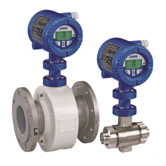
- Page 1 JUMO flowTRANS MAG S/H Electromagnetic flowmeter for the process industry and hygienic applications Safety Manual Ex for device versions 406012 - 406019 40601200T99Z001K000 V5.00/EN/00643289...
-
Page 3: Table Of Contents
JUMO flowTRANS MAG S/H - remote mount design ....... . - Page 4 Contents Ex relevant data for operation in zones 1, 21 and 22 ....25 Electrical connection ............25 4.1.1 Sensor and transmitter in zone 1 .
-
Page 5: Safety
Other applicable device documentation For measuring systems used in potentially explosive areas, this document "JUMO flowTRANS MAG S/ H - Ex Safety Manual for Devices 406012 - 406019" supplements the operating manual "JUMO flowTRANS MAG S/H for Devices 406012 - 406019". -
Page 6: Symbols And Signal Words
1 Safety Symbols and signal words DANGER – Serious damage to health/risk to life! This symbol in connection with the signal word "Danger" indicates an imminent threat of danger. Failure to observe the safety information results in death or serious injuries. DANGER –... -
Page 7: Device Versions
1st and 2nd basic type supplements. Based on this device designation, the device ver- sions can be distinguished. The device designation is explained in full in the operating manual "JUMO flowTRANS MAG S/H“, chap- ter 2 "Layout and function", starting on page 22. -
Page 8: Explosion Protection
CD or at www.jumo.de). JUMO flowTRANS MAG electromagnetic flowmeters are available for use in potentially explosive areas. The design type for potentially explosive areas is indicated by the digit "1" in the 2nd basic type supple- ment of the device designation. -
Page 9: Jumo Flowtrans Mag S/H - Compact Design
2 Device versions JUMO flowTRANS MAG S/H - compact design Sensor and transmitter form a mechanical unit. 2.4.1 ATEX/IECEx Zone 1 JUMO flowTRANS MAG S01/S02 JUMO flowTRANS MAG H01/H02 406012/1-1 (Ex-protection zone 1) 406015/1-1 (Ex-protection zone 1) 406013/1-1 (Ex-protection zone 1) -
Page 10: Jumo Flowtrans Mag S/H - Remote Mount Design
Ex e ia IIC T6 ... T2 Gb Ex tb IIIC T70° C ... T Ex tb [ia Db] IIIC T70° C Db Medium NOTE The JUMO flowTRANS MAG H model series with a remote mount design is not available for ATEX/ IECEx zone 1. -
Page 11: Atex/Iecex Zone 2
The electrical connection between the transmitter and sensor may only be established using the signal cable included in the scope of delivery. see chapter 2.5.3 "Signal cable length and preamplifier", page 12. JUMO flowTRANS MAG S01/S02 JUMO flowTRANS MAG H01/H02 406012/2-1 (Ex-protection zone 2) -
Page 12: Signal Cable Length And Preamplifier
2 Device versions 2.5.3 Signal cable length and preamplifier For devices in the remote mount design, the electrical connection between the transmitter and sensor is made via a signal cable. Transmitter housing Single-compartment Ex-zone 2 Ex-zone 2 or design housing outside the Ex-area Maximum signal cable 406018/2-0... -
Page 13: Overview: The Fast Way To The Devices
This Ex-safety information applies in connection with the following inspection documents and certifi- cates: Scope of application Inspection documents/certificates ATEX FM15ATEX0024X, FM15ATEX0025X IECEx FME 15.0006X JUMO flowTRANS MAG S01/S02 Model in the Ex-area Electrical Electrical Temperature Connection Data data 406012/1-1 in zone 1, 21 ... -
Page 14: Nameplate
2 Device versions Nameplate 2.7.1 Nameplate for compact design (dual-compartment housing) Model number (for technical version details, see data sheet or order confirmation) Serial number for identification by the manufacturer Nominal width and nominal pressure levels Material: flange/lining/electrode = Maximum admissible measurement medium temperature = Maximum admissible ambient temperature Calibration value Qmax DN Calibration value Ss (range) -
Page 15: Nameplate For Compact Design (Single-Compartment Housing)
2 Device versions 2.7.2 Nameplate for compact design (single-compartment housing) Nameplate Model number (for technical version details, see data sheet or order confirmation) Serial number for identification by the manufacturer Nominal width and nominal pressure levels = Maximum admissible measurement medium temperature = Maximum admissible ambient temperature Protection type according to DIN EN 60529 Calibration value Qmax DN... -
Page 16: Nameplate For Remote Mount Design
2 Device versions 2.7.3 Nameplate for remote mount design Model number (for technical version details, see data sheet or order confirmation) Serial number for identification by the manufacturer Nominal width and nominal pressure levels Material: flange/lining/electrode Customer-specific TAG number (if provided) = Maximum admissible measurement medium temperature = Maximum admissible ambient temperature Protection type according to DIN EN 60529... -
Page 17: Nameplate Of The Transmitter (Dual-Compartment Housing)
2 Device versions 2.7.4 Nameplate of the transmitter (dual-compartment housing) Model number (for technical version details, see data sheet or order confirmation) Serial number for identification by the manufacturer Customer-specific TAG number (if provided) = Maximum admissible ambient temperature Protection type according to DIN EN 60529 Voltage supply Transmitter communication protocol Software version... -
Page 18: Nameplate Of The Transmitter (Single-Compartment Housing)
2 Device versions 2.7.5 Nameplate of the transmitter (single-compartment housing) Nameplate Model number (for technical version details, see data sheet or order confirmation) Serial number for identification by the manufacturer Voltage supply = Maximum admissible ambient temperature Transmitter communication protocol CE mark Order number Customer-specific TAG number (if provided) -
Page 19: Mounting
3 Mounting Notes on opening and closing the housing To install, start up and maintain the JUMO flowTRANS MAG devices, it is necessary to open the housing of the sensor or transmitter. Be sure to observe the following safety instructions before opening and after closing the housing for re- starting: DANGER –... -
Page 20: Opening The Case Lid (Single-Chamber Housing)
3 Mounting 3.1.2 Opening the case lid (single-chamber housing) Recessed head screws 1. Observe chapter 3.1 "Notes on opening and closing the housing", page 19! 2. Loosen the recessed head screws (1) and remove the case lid. 3. Relocate the case lid and screw down the recessed head screw (1) tightly before re-starting. 3.1.3 Rotation of the transmitter housing Dual-compartment housing... -
Page 21: Turning The Lcd Display
3 Mounting 3.1.4 Turning the LCD display Depending on the installation position, the LCD display or transmitter housing can be rotated to allow for horizontal read-off. Transmitter with LCD display Housing for transmitter plug-in module Rotation lock 1. Switch off voltage supply. 2. -
Page 22: Protection Type Ip68
3 Mounting Black cable fittings are installed at the factory. If signal outputs are connected to intrinsically safe elec- trical circuits, we recommend replacing the black caps on the respective cable fittings with the blue ones provided. Protection type IP68 WARNING –... -
Page 23: Notes On Using The Device In Areas With Combustible Dust
3 Mounting Notes on using the device in areas with combustible dust DANGER – Explosion hazard! Among other things, the dust explosion protection is ensured by the housing. No changes may be made to the housing (e.g. removing or not using parts). The device with dual-compartment transmitter housing is approved for use in potentially explosive areas (gas and dust). -
Page 24: Installation Of The High-Temperature Version
3 Mounting Installation of the high-temperature version Complete thermal insulation of the sensor part is required for the high-temperature version. The pipeline and sensor insulation (1) must be implemented as shown in the figure after installing the device. The thermal resistance of the insulation must not exceed λ = 0.036 W/(mK); otherwise reduce the insu- lation thickness. -
Page 25: Ex Relevant Data For Operation In Zones 1, 21 And 22
Ex relevant data for operation in zones 1, 21 and 22 4 Ex relevant data for operation in zones 1, 21 and 22 Electrical connection 4.1.1 Sensor and transmitter in zone 1 Modell 406012/1-1, 406013/1-1, 406015/1-1, 406012/2-1 with 406018/2-1, 406013/2-1 with 406019/2-1 HART protocol, PROFIBUS-PA, FOUNDATION Fieldbus Ex-zone 1 A = Transmitter, B = Sensor... - Page 26 4 Ex relevant data for operation in zones 1, 21 and 22 Input and output connection Terminal Function 31/32 Current/HART output - The current output is available in "active" or "passive" mode. The configuration must be specified when ordering the unit, since the configuration cannot be changed on-site. 97/98 PROFIBUS-PA (PA+/PA-) or FOUNDATION Fieldbus (FF+/FF-) –...
-
Page 27: Sensor In Zone 1 And Transmitter In Zone 2 Or Outside Of The Ex-Area
4 Ex relevant data for operation in zones 1, 21 and 22 4.1.2 Sensor in zone 1 and transmitter in zone 2 or outside of the Ex-area Modell 406012/2-1 with 406018/2-1 or with 406018/2-0, 406013/2-1 with 406018/2-1 or with 406018/2-0 HART protocol, PROFIBUS-PA, FOUNDATION Fieldbus Ex-zone 1 Ex-zone 2... - Page 28 4 Ex relevant data for operation in zones 1, 21 and 22 Input and output connection Terminal Function 31/32 Current/HART output - The current output is available in "active" or "passive" mode. 97/98 PROFIBUS-PA (PA+/PA-) or FOUNDATION Fieldbus (FF+/FF-) – according to IEC 61158-2 51/52 Digital output DO1 active/passive - Function can be configured locally as "Pulse output"...
-
Page 29: Electrical Data For Operation In Zones 1, 21, 22
4 Ex relevant data for operation in zones 1, 21 and 22 Electrical data for operation in zones 1, 21, 22 4.2.1 Devices with HART protocol When operating in potentially explosive areas, observe the following electrical data for the transmitter signal inputs and outputs. - Page 30 4 Ex relevant data for operation in zones 1, 21 and 22 IMPORTANT (NOTE)! Special connection conditions: The output circuits are designed so that they can be connected to intrinsically safe and non-intrinsically safe electrical circuits. Intrinsically safe and non-intrinsically safe electrical circuits may not be combined. Potential equalization must be implemented for intrinsically safe circuits.
-
Page 31: Devices With Profibus Pa Or Foundation Fieldbus
4 Ex relevant data for operation in zones 1, 21 and 22 4.2.2 Devices with PROFIBUS PA or FOUNDATION Fieldbus Operation in zone 1 – Devices with PROFIBUS PA or FOUNDATION Fieldbus When operating in potentially explosive areas, observe the following electrical data for the transmitter signal inputs and outputs. - Page 32 4 Ex relevant data for operation in zones 1, 21 and 22 IMPORTANT (NOTE)! Special connection conditions: The output circuits are designed so that they can be connected to intrinsically safe and non-intrinsically safe electrical circuits. Intrinsically safe and non-intrinsically safe electrical circuits may not be combined. Potential equalization must be implemented for intrinsically safe circuits.
-
Page 33: Temperature Data For Operation In Zone 1
4 Ex relevant data for operation in zones 1, 21 and 22 Temperature data for operation in zone 1 Operation in zone 1 Model Surface temperature 406012/1-1 406013/1-1 70 °C (158 °F) 406015/1-1 406016/1-1 406012/2-1 85 °C (185 °F) 406013/2-1 406018/2-1 (dual-compartment housing) 70 °C (158 °F) 406019/2-1 (dual-compartment housing) - Page 34 4 Ex relevant data for operation in zones 1, 21 and 22 Table 2: Medium temperature (Ex data) for model 406012/1-1, 406013/1-1, 406015/1-1, 406016/1-1 IMPORTANT (NOTE)! If the installation location for the device is classified as a potentially explosive area for gases and dust, the temperature data in the "Gas &...
- Page 35 4 Ex relevant data for operation in zones 1, 21 and 22 High-temperature version Ambient temperature (-40 °C) -20 °C to +40 °C (-40 °C) -20 °C to +50 °C (-40 °C) -20 °C to +60 °C Not thermal- Thermally Not thermal- Thermally Not thermally...
- Page 36 4 Ex relevant data for operation in zones 1, 21 and 22 Table 3: Medium temperature (Ex data) for model 406012/2-1, 406013/2-1 IMPORTANT (NOTE)! The standard version includes Ex-protection for gases and dust. If the installation location for the device is classified as a potentially explosive area for gases and dust, the temperature data in the "Gas &...
- Page 37 4 Ex relevant data for operation in zones 1, 21 and 22 High-temperature version Ambient temperature (-40 °C) -20 °C to +40 °C (-40 °C) -20 °C to +50 °C (-40 °C) -20 °C to +60 °C Not thermal- Thermally Not thermal- Thermally Not thermally...
- Page 38 4 Ex relevant data for operation in zones 1, 21 and 22...
-
Page 39: Ex-Relevant Data For Operation In Zones 2, 21 And 22
Ex-relevant data for operation in zones 2, 21 and 22 5 Ex-relevant data for operation in zones 2, 21 and 22 Electrical connection 5.1.1 Sensor and transmitter in zone 2 or outside of the Ex-area Models 406012/1-1, 406013/1-1, 406015/1-1. 406016/1-1, 406012/2-1 or 406015/2-1 with 406018/2-1 or with 406018/2-0, 406013/2-1 or 406016/2-1 with 406019/2-1 or with 406019/2-0 HART protocol, PROFIBUS-PA, FOUNDATION Fieldbus Ex-zone 2... -
Page 40: Electrical Data For Operation In Zones 2, 21, 22
5 Ex-relevant data for operation in zones 2, 21 and 22 Input and output connection Termi- Function 31/32 Current/HART output - The current output is available in "active" or "passive" mode. 97/98 PROFIBUS-PA (PA+/PA-) or FOUNDATION Fieldbus (FF+/FF-) – according to IEC 61158-2 51/52 Digital output DO1 active/passive - Function can be configured locally as "Pulse output"... -
Page 41: Devices With Profibus Pa Or Foundation Fieldbus
5 Ex-relevant data for operation in zones 2, 21 and 22 5.2.2 Devices with PROFIBUS PA or FOUNDATION Fieldbus When operating in potentially explosive areas, observe the following electrical data for the transmitter signal inputs and outputs. For the (PROFIBUS-PA) version, see the identification marking in the device's terminal box. - Page 42 5 Ex-relevant data for operation in zones 2, 21 and 22 Table 1: Medium temperature depending on the lining and flange material Model 406012/1-1, 406013/1-1, 406012/2-1, 406013/2-1 Materials Medium temperature (operating data) Lining Flange Minimum Maximum Steel -10 °C (14 °F) Hard rubber 90 °C (194 °F) Stainless steel...
- Page 43 5 Ex-relevant data for operation in zones 2, 21 and 22 Table 2: Medium temperature (Ex data) for model 406012/1-1, 406013/1-1, 406015/1-1, 406016/1-1 IMPORTANT (NOTE)! If the installation location for the device is classified as a potentially explosive area for gases and dust, the temperature data in the "Gas &...
- Page 44 5 Ex-relevant data for operation in zones 2, 21 and 22 High-temperature version Ambient temperature (-40 °C) -20 °C to +40 °C (-40 °C) -20 °C to +50 °C (-40 °C) -20 °C to +60 °C Not thermal- Thermally Not thermal- Thermally Not thermally Thermally in-...
- Page 45 5 Ex-relevant data for operation in zones 2, 21 and 22 Table 3: Medium temperature (Ex data) for model 406012/2-1, 406013/2-1, 406015/2-1, 406016/2-1 IMPORTANT (NOTE)! If the installation location for the device is classified as a potentially explosive area for gases and dust, the temperature data in the "Gas &...
- Page 46 5 Ex-relevant data for operation in zones 2, 21 and 22 High-temperature version Ambient temperature (-40 °C) -20 °C to +40 °C (-40 °C) -20 °C to +50 °C (-40 °C) -20 °C to +60 °C Not thermal- Thermally Not thermal- Thermally Not thermally Thermally in-...
-
Page 47: Startup
Startup 6 Startup Checks prior to start-up IMPORTANT (NOTE)! The following points must be checked before startup: • The voltage supply must be switched off. • The voltage supply must match the specification on the nameplate. • The pin assignment must correspond to the connection diagram. •... -
Page 48: Special Features Of Device Version For Operation In Ex Zone 1
6 Startup Special features of device version for operation in Ex zone 1 6.3.1 Configuring the current output For devices designed for use in Ex-zone 1, the current output configuration cannot be subsequently changed. The desired configuration for the current output (active/passive) must be specified when the order is placed. - Page 49 6 Startup The configuration jumpers are located on the backplane in the transmitter housing. HART protocol PROFIBUS PA FOUNDATION Fieldbus BR902 for digital output DO1 BR901 for digital output DO2 BR902 in position 1: standard (non-NAMUR) BR901 in Position 1: Standard (non-NAMUR) BR902 in position 2: NAMUR BR901 in position 2: NAMUR Case lid...
- Page 50 6 Startup...
-
Page 51: Maintenance
All repair or maintenance work must only be carried out by qualified customer service personnel. When replacing or repairing individual components, original spare parts must be used. To install, start up and maintain the JUMO flowTRANS MAG devices, it is necessary to open the housing of the sensor or transmitter. -
Page 52: Replacing The Transmitter Or Sensor
MAG S01 or JUMO flowTRANS MAG H02). After the transmitter is replaced, the system data must be reloaded according to the specifications in chapter 7.5.1 "Loading the system data" of the „JUMO flowTRANS MAG S/H - Operating Manual for the devices 406012 - 406019". -
Page 53: Replacing The Transmitter
8. Close the case lid and secure the lid by unscrewing the lid lock (4). 9. Reload the system data, See operating manual "JUMO flowTRANS MAG S/H for the devices 406012 - 406019", chapter 7.5.1 "Loading the system data". - Page 54 7 Maintenance...
-
Page 55: Annex
Identification marking for intended use in potentially explosive areas according to: • ATEX Directive (identification marking in addition to CE mark) • IECEx standards IMPORTANT (NOTE)! All the documentation, declarations of conformity and certificates are also available in the download area www.jumo.de. - Page 56 8 Annex...
- Page 58 JUMO GmbH & Co. KG JUMO Instrument Co. Ltd. JUMO Process Control, Inc. Street address: JUMO House 6733 Myers Road Moritz-Juchheim-Straße 1 Temple Bank, Riverway East Syracuse, NY 13057, USA 36039 Fulda, Germany Harlow, Essex, CM20 2DY, UK Delivery address:...
Need help?
Do you have a question about the flowTRANS MAG S Series and is the answer not in the manual?
Questions and answers