JUMO flowTRANS US W02 Brief Instructions
Ultrasonic flow meter for liquids
Hide thumbs
Also See for flowTRANS US W02:
- Brief instructions (48 pages) ,
- Operating manual (62 pages)

Related Manuals for JUMO flowTRANS US W02


Summary of Contents for JUMO flowTRANS US W02
- Page 1 JUMO flowTRANS US W02 Ultrasonic flow meter For liquids Brief Instructions 40605100T97Z101K000 V1.01/EN/00769022/2022-06-29...
- Page 2 Further information and downloads qr-406051-en.jumo.info...
-
Page 3: Table Of Contents
Contents Contents About this documentation ........6 Purpose. - Page 4 Contents Acceptance of goods, storage, and transport ..... 19 Scope of delivery ............19 Checking the delivery .
- Page 5 Contents Shutdown ........... 43 12.1 Uninstalling the device .
-
Page 6: About This Documentation
About this documentation 1 About this documentation Purpose This documentation is part of the device and includes all information to ensure that it is used safely and as intended across all phases of the product lifecycle. If you do not follow the documentation and safety information, this may result in risk to life and damage to property due to improper use. -
Page 7: Safety
Safety 2 Safety Safe operation This device is built based on current state-of-the-art technology and is safe to use. The device has been tested and was shipped from the plant in perfect working order. If you do not follow the measures to ensure safe operation, this may result in risk to life and damage to property due to improper use. -
Page 8: Hazardous Materials
Declarations of conformity Radio Equipment Directive (RED) JUMO GmbH & Co. KG hereby states that the flowTRANS US W02 device complies with the Directive 2014/53/EU. The full text of the EU Declaration of Conformity is available at the following web address: qr-406051-en.jumo.info. -
Page 9: Device Description
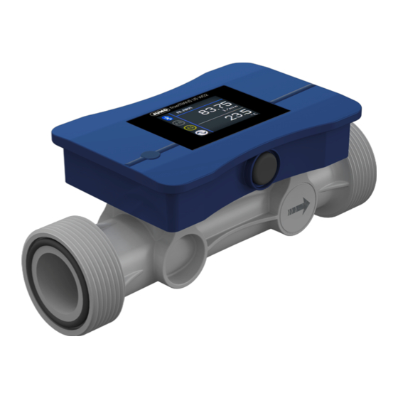
Device Description 3 Device Description Design Front view Rear view Measuring tube Display (TFT display) Transducer (ultrasonic converter) O-ring (seal for the process connection) Housing for electronic components M12 plug connection (4-pole) Function The transducers are on opposite sides of the measuring section and act as transmitters and receivers, i.e. -
Page 10: Nameplate
3 Device Description Nameplate (2)(3) (4) 3 6 0 3 9 Fu l d a G e r m a n y (10) (11) (12) (13) (14) (15) Manufacturer and address Device ID Nominal width Voltage supply Nominal pressure level Symbol for direct voltage) EU conformity label Medium temperature... -
Page 11: Device Id
The IODD is required for communication with the device via an IO-Link interface "IO-Link", Page 31. Nominal width: DN 15 with low-flow calibration Device ID Device version IODD 0x18403_ DN15LF flowmeter JUMO-184031-*.xml 0x1840B_ DN15LF flowmeter/pressure sensor 0 to 2.5 bar rel. JUMO-1840B1-*.xml 0x18413_ DN15LF flowmeter/pressure sensor -1 to +6 bar rel. JUMO-184131-*.xml 0x1841B_ DN15LF flowmeter/pressure sensor -1 to +10 bar rel. -
Page 12: Technical Data
Technical data 4 Technical data Electrical data Voltage supply DC 18 to 30 V SELV, PELV, Class 2 Current consumption ≤ 100 mA, with switching outputs ≤ 600 mA Power consumption ≤ 10 W Protection rating DIN EN 61140, Class III (protective low voltage ) Electrical safety The device must be equipped with an electrical circuit that meets the require- ments of DIN EN 61010-1 with regard to "Limited-energy circuits". -
Page 13: Temperature Input
4 Technical data 4.2.3 Temperature input Measuring range -40 to +125 °C Accuracy ±2 K 4.2.4 Pressure input (optional) Measuring range up to 16 bar relative Accuracy at 20 °C ±0.4% MSP at -20 to +100 °C ±1% MSP Includes: linearity, hysteresis, repeatability, deviation of measuring range initial value, and measuring range end value. -
Page 14: Digital Output
4 Technical data 4.3.2 Digital output Type Transistor output as switching output or pulse output (I/O Pin 1 only) Protection Against polarity reversal, short circuiting and overload Output signal Push-pull, PNP, NPN Ampacity ≤ 200 mA Voltage drop ≤ 3 V Switching output Function Output signal... -
Page 15: Interfaces
4 Technical data Interfaces 4.4.1 Bluetooth Communication Via (mobile) end device with JUMO smartCONNECT app Authentication Via Bluetooth radio module and NFC tag Connection status (configurable) Permanently Active Temporarily Restricted (via NFC) Range 10 m under rerference conditions Radio frequency Bluetooth radio module 2.45 GHz... -
Page 16: Environmental Influences
4 Technical data Environmental influences Admissible ambient temperature DIN 60068-2-1, DIN 60068-2-2 At a medium temperature ≤ 80 °C -20 to +60 °C At medium temperature of -20 to +45 °C > 80 °C Admissible storage temperature -20 to +60 °C Climatic conditions DIN EN 60721-3-1, DIN EN 60721-3-3, DIN EN 60068-2-78 Climate class... -
Page 17: Nominal Pressure
4 Technical data 4.7.2 Nominal pressure Nominal pressure levels PN 16 4.7.3 Pressure loss diagram Created under reference conditions "Reference conditions", Page 12. X = Flow mbar Y = Pressure loss (mbar) DN 15 DN 25 DN 20 DN 15 low DN 32 Measurement media Medium type... -
Page 18: Dimensions
4 Technical data Dimensions ØDi flowTRANS US W02 Nominal ØDi [mm] A [mm] B [mm] C [mm] L [mm] width DN 15 16.5 G 1″ 43.5 DN 20 21.5 G 1 1/4″ DN 25 G 1 1/2″ DN 32 G 2″... -
Page 19: Acceptance Of Goods, Storage, And Transport
5 Acceptance of goods, storage, and transport Scope of delivery 1× JUMO flowTRANS US W02 – Device in the ordered version, including calibration certificate 2× O-ring (seal for the process connection) in the ordered version 1× JUMO flowTRANS US W02 operating manual Checking the delivery •... -
Page 20: Installation
Installation 6 Installation Prepare installation Requirements: • Check the environmental influences to which the device will be exposed. • De-energize the system and secure it against being switched on again. • Stop medium circulation in the plant. • Drain and flush the pipe. •... - Page 21 6 Installation Avoid mechanical strain Ensure that the center lines of both ends of the pipes align be- fore installing in the pipe (3). Align the ends of the pipes parallel and at an angle to one another. Adhere to the insertion length L of the device.
-
Page 22: Installing The Device
6 Installation Installing the device 1. Insert the O-rings supplied into the sealing ring grooves in the two process connections. 2. Install the device between the two union ends of the mounting set. Ensure that the O-rings (2) be- tween the process connections (1) and union ends (3) are cor- rectly positioned. -
Page 23: Electrical Connection
Electrical connection 7 Electrical connection Preparing the electrical connection Requirements: • Switch off the plant's voltage and secure it so that it cannot switch on again. • Correctly prepare the connections for the voltage supply and signal processing. The device must be equipped with an electrical circuit that meets the requirements of DIN EN 61010-1 with regard to "Limited-energy circuits". -
Page 24: Connecting The Digital Input
7 Electrical connection 7.1.2 Connecting the digital input PLC level: logic level "0" < 7 V, logic level "1" > 15 V +24 V I/O Pin 2 I/O Pin 1 Device Connecting cable 7.1.3 Connection of analog output I/O Pin 1 and/or I/O Pin 2 can be configured as analog output. The connection examples for I/O Pin 2 also apply to I/O Pin 1. -
Page 25: Connection Of Digital Output
7 Electrical connection 7.1.4 Connection of digital output I/O Pin 1 and/or I/O Pin 2 can be configured as digital output. I/O Pin 1 can be configured as switching or pulse output; I/O Pin 2 can be configured as switching output. Requirements: •... -
Page 26: Connecting The Device
7 Electrical connection Digital output – PNP +24 V I/O Pin 2 ≤ 200 mA, ≤ 10 kHz I/O Pin 1 Device Connecting cable Connecting the device 1. Insert the connecting cable into the M12 plug connection. 2. Manually screw the union nut of the connecting cable onto the M12 plug connection on the de- vice... -
Page 27: Operation
BT SW: 464.01.01 I/O HW: 01.01 BT SW: 464.01.01 TAG: JUMO flowTRANS US TAG: JUMO flowTRANS US W02 Orientation: 0°, 180° Orientation: 90°, 270° Pos. Designation Description Startup display Shows the device software version. 2, 3 Shows the device hardware version. - Page 28 8 Operation Status bar Pos. Symbol, display Description ALARM Shows a device error or a warning. BATCH Shows an active batch operation. Shows an input that is in simulation mode. Process value display 1, Process value display 2 Totalizer, totalizer transmission Only appears when the totalizer function is active.
- Page 29 8 Operation System unit Pos. Symbol, display Description l/s, m /h, ft /min, l/min, ft Shows the configured system unit of the process value. usgal/min, impgal/min, l/h, /s, usgal/h, impgal/h, °C, °F, mbar, bar, psi, m/s, %, l, usgal, impgal, m , ft Toolbar Interface connections...
- Page 30 8 Operation I/O Pin 1 Shows the configuration, function and status of the device I/O Pin 1. Pos. Symbol, display Description Configuration: IO-Link Configuration: Analog output Configuration: Digital output Function: Switching output, pulse output Status: Inactive (switching output) Configuration: Digital output Function: Switching output Status: Active I/O Pin 2...
-
Page 31: Interfaces
8.2.1 Bluetooth The JUMO smartCONNECT app allows the device to be configured and its parameters to be set using an end device. Configuration data and device information are transmitted via Bluetooth. The Bluetooth radio module of the device is permanently active during initial startup. -
Page 32: Configuration
Configuration 9 Configuration Default settings The parameter list is based on the JUMO smartCONNECT app operating menu. The table headings lo- cate the respective parameters in the app operating menu. Sensor > display Parameter Value Default setting Description Language German; English;... - Page 33 Parameter function. output, digital out- Input/output 1 > IO-Link Parameter Value Default setting Description Application-spe- JUMO TAG designation (text input with max. 32 cific marking flowTRANS US characters possible). System designa- TAG designation (text input with max. 32 tion characters possible).
- Page 34 9 Configuration Parameter Value Default setting Description Error behavior Low, high, frozen, Output signal in the event of a malfunction substitute value Low: 3.4 mA or 0 V High: 22 mA or 11 V Frozen: Last valid value Replacement value: Specified replacement value Replacement val- Input range:...
- Page 35 9 Configuration Parameter Value Default setting Description Switch-off delay Input range: 0.000 Input value in s. 0.000 to 100.0 Error behavior Inactive, active, Inactive Behavior of the output signal in case of a frozen malfunction Error behavior Inaktiv value: If the function parameter of digital output 1 is configured as a switching output value, a process value error sets the switching output to inactive.
- Page 36 9 Configuration Parameter Value Default setting Description Replacement val- Input range: Parameter error behaviour must be config- 0.000 to 22.00 ured as a replacement value value. Input range: 3.4 to 22 mA (current output) 0 to 11 V (voltage output) Input/output 2 >...
- Page 37 9 Configuration Error behavior Inavtive value: If the function parameter of digital output 2 is configured as a switching output, a pro- cess value error sets this value to inactive. Frozen value: If the function parameter of digital output von 1 is configured as a switching output val- ue, a process value does not have any influence on the configuration of this value.
- Page 38 9 Configuration Parameter Value Default setting Description Set ACTUAL start Inactive, adopt Inactive Travel to actual starting value and use value actual start value adopt actual start value to adopt the mea- sured flow value. Alternatively: parameter actual start value Set actual end Inactive, adopt Inactive...
- Page 39 9 Configuration Simulation > flow Parameter Value Default setting Description Simulation On, Off Parameter function. Value Input range: 0.000 Input value for the simulation. -99999 to 99999 Simulation > temperature Parameter Value Default setting Description Simulation On, Off Parameter function. Value Input range: 0.000...
-
Page 40: Troubleshooting
Troubleshooting 10 Troubleshooting 10.1 Process value error Process value errors are displayed flashing instead of the process value. With error messages in line with the NAMUR classification NE 107, process value errors are supplemented by symbols and a two- line message (alternating with the process display). Message Cause Remedy... -
Page 41: Error Messages Outside Namur
10 Troubleshooting Symbol Designation Functional check Message Cause Remedy Simulation Simulation mode is active. Deactivate simulation mode. Alterna- active tively: Restart device. Symbol Designation Outside the specification Message Cause Remedy Outside the The device is operated outside the de- Operate the device within the device specification vice specifications. -
Page 42: Maintenance And Cleaning
Maintenance and cleaning 11 Maintenance and cleaning 11.1 Cleaning device housing The device housing can be cleaned when the device has been installed. Clean the device with a cloth dampened with water. 11.2 Cleaning parts that come into contact with the medium and replacing O- rings Requirements: •... -
Page 43: Shutdown
• Decontaminate the device "Decontaminating the device", Page 42. 1. The supplementary sheet for product returns (http://productreturn.jumo.info) must first be completed correctly and signed. Then enclose it with the shipping documents and attach it to the packaging, ideally on the outside. -
Page 44: Accessories
Accessories 13 Accessories Designation Part no. Mounting set PVC DN 15 with PP nut 00750871 PVC DN 20 with PP nut 00750872 PVC DN 25 with PP nut 00750874 PVC DN 32 with PP nut 00750876 PP socket welding DN 15 00750888 PP socket welding DN 20 00750890... -
Page 45: China Rohs
China RoHS 14 China RoHS Product group: 406051 China EEP Hazardous Substances Information Component Name Hg ) Cr(VI) PBDE Housing (Gehäuse) Process connection (Prozessanschluss) Nuts (Mutter) Screw (Schraube) (Leiterplatte) SJ/T 11364 This table is prepared in accordance with the provisions SJ/T 11364. ○... - Page 46 14 China RoHS...
- Page 48 JUMO GmbH & Co. KG JUMO Instrument Co. Ltd. JUMO Process Control, Inc. Street address: JUMO House 6724 Joy Road Moritz-Juchheim-Straße 1 Temple Bank, Riverway East Syracuse, NY 13057, USA 36039 Fulda, Germany Harlow, Essex, CM20 2DY, UK Delivery address:...
Need help?
Do you have a question about the flowTRANS US W02 and is the answer not in the manual?
Questions and answers