
Subscribe to Our Youtube Channel
Related Manuals for JUMO flowTRANS MAG H20


Summary of Contents for JUMO flowTRANS MAG H20
- Page 1 JUMO flowTRANS MAG H20 Electromagnetic flowmeter for liquids Operating manual SPE variant 40606512T90Z001K000 V1.00/EN/30050670/2023-07-17...
- Page 2 Further information and downloads qr-406065-en.jumo.info...
-
Page 3: Table Of Contents
Table of contents Table of contents About this documentation ........6 Validity. - Page 4 JUMO Cloud ........
- Page 5 Table of contents 10.3.1 Flow ..............40 10.3.2 Temperature .
-
Page 6: About This Documentation
1 About this documentation About this documentation Validity This manual is valid for all devices with an SPE interface (Single Pair Ethernet). Purpose This documentation is part of the device and includes all information to ensure that it is used safely and as intended across all phases of the product lifecycle. -
Page 7: Abbreviations
1 About this documentation Abbreviations Conformité Européenne (European Conformity) DHCP Dynamic Host Configuration Protocol (communication protocol for automatic assignment of the network configuration) Data Matrix Code Diamètre Nominal (nominal diameter) Domain Name System Electromagnetic compatibility Federal Communications Commission (issues FCC certification for electronic products sold or manufactured in the United States) Food and Drug Administration (US-amerikanische Arzneimittelbehörde;... -
Page 8: Definition Of Terms
1 About this documentation Definition of terms Use in the documentation Definition Device Electromagnetic flowmeter for liquids Medium, measurement medi- Conductive liquid for which flow and temperature are measured Product lifecycle Overall consideration of product identification, acceptance of the goods, storage, mounting, connection, operation, troubleshooting, maintenance to disposal Flow Totalized flow rate per time span... -
Page 9: Safety
2 Safety Safety Intended use The device is intended for measuring the flow and temperature of liquid media having a minimum con- ductivity of 20 μS/cm and a maximum viscosity of 70 mPa·s. In order to ensure the device's perfect condition, only media may be used to which the materials in con- tact with the media are sufficiently resistant. -
Page 10: Hazardous Materials
2 Safety Hazardous materials Using hazardous materials as a medium may result in abrasive and corrosive damage to components of the device that come into contact with the medium. The medium may leak and present a fire hazard and a risk to health. Carry out a risk assessment taking into consideration the safety data sheet for the relevant hazardous substance for mounting, operation, maintenance, cleaning, and disposal: •... -
Page 11: Description
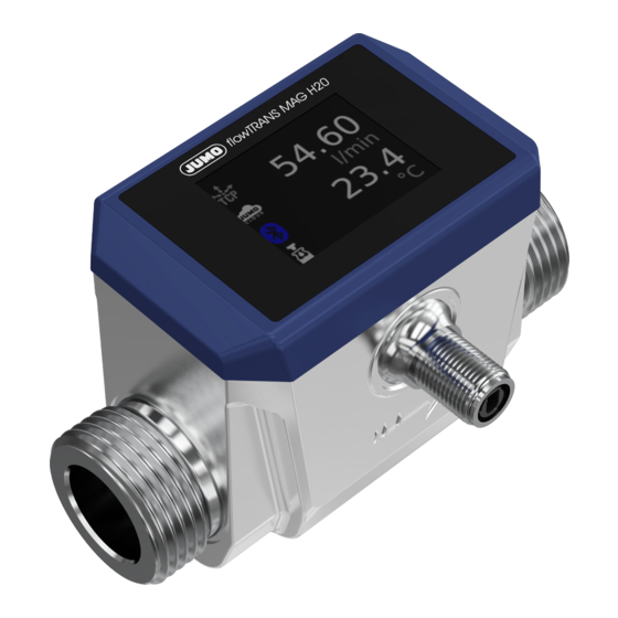
3 Description Description Scope of delivery Device in the ordered version Quick start guide 2 × Centellen seals (only for variant with thread connection) → no FDA approval Structure Device cover Flow direction arrow Process connection M12 connector Display Stainless steel case Function The device records the flow according to the principle of electromagnetic flow measurement. -
Page 12: Nameplate
3 Description Nameplate Manufacturer and address Device designation flowTRANS MAG H20 Product group number Part no. Input: Flow measuring range Eingang: Spannungsart und Spannungsversorgung → Zeichen für Gleichspannung) Maximum power consumption in watts [W] ...W DN... Nominal width Nominal pressure level PN... -
Page 13: Technical Data
4 Technical data Technical data Inputs, measurands Reference conditions Measurement medium Water Medium temperature 23 °C ±5 °C Ambient temperature 23 °C ±5 °C Medium pressure 1 to 4 bar Measuring pipe Horizontal installation Flow Maximum measuring range DN 6 0.005 to 5.000 l/min DN 15 0.050 to 35.000 l/min... -
Page 14: Interfaces
4 Technical data Interfaces 4.2.1 Bluetooth Communication Via mobile end device with the "JUMO smartCONNECT" app Authentication Via NFC Connection status (configurable) Active Inactive Restricted (can be activated via NFC) Range 10 m (open space) Radio frequency Bluetooth radio module 2.45 GHz... -
Page 15: Display
4 Technical data Display Type TFT display Size Display range 35.04 × 28.03 mm Screen size (diagonal) 1.77″ Dissolution 128 × 160 (RGB) Brightness 10 levels (configurable) Environmental influences Admissible ambient temperature DIN 60068-2-1, DIN 60068-2-2 At medium temperature ≤ 80 °C -20 to +60 °C At medium temperature >... -
Page 16: Nominal Pressure
4 Technical data 4.5.2 Nominal pressure Nominal pressure level PN 16 4.5.3 Pressure loss diagram X = maximum flow (%) Y = pressure loss (mbar) Measurement media Medium type Conductive liquids Conductivity ≥ 20 µS/cm Viscosity ≤ 70 mPa·s Temperature range -20 °C to +90 °C Return to the accuracy specifications after cooling down. -
Page 17: Dimensions
4 Technical data Dimensions 4.7.1 Thread connection according to DIN EN ISO 228-1 Ø flowTRANS MAG H20 Nominal Ø Di [mm] Ø D [″] A [mm] B [mm] C [mm] L [mm] H [mm] width DN 6 DN 15 12.5 DN 20 15.0... -
Page 18: Tri-Clamp Connection According To Din 32676, Series A
4 Technical data 4.7.2 Tri-Clamp connection according to DIN 32676, Series A Ø flowTRANS MAG H20 Nominal Ø Di [mm] Ø D [mm] A [mm] B [mm] C [mm] L [mm] H [mm] width DN 6 25.0 DN 15 12.5 34.0... -
Page 19: Transport And Storage
5 Transport and storage Transport and storage Transport If the device is not protected properly against external influences, it may become damaged during trans- port. • Transport the device in an impact-proof packaging solution that protects it against moisture and dirt. •... -
Page 20: Installation
6 Installation Installation Preparing for installation 6.1.1 Installation site The device is protected against electromagnetic interference. The device is protected from UV radiation. The device is protected from the weather when used outside. 6.1.2 Inlet and outlet sections No straight inlet or outlet sections are required to operate the device. 6.1.3 Installation position Flow direction... -
Page 21: Avoid Mechanical Strain
6 Installation 6.1.4 Avoid mechanical strain Install the device free of mechanical stress so that no pipeline forces can be transmitted to the device. Important: • Take into account the insertion length of the device including the two pipe adapters (X). •... -
Page 22: Alignment Of The Housing For Electronic Components
6 Installation 6.1.6 Alignment of the housing for electronic components The maximum admissible display temperature of 70 °C must not be exceeded. Appropriate measures must be taken to ensure compliance with the temperature limit. For this purpose, it can be helpful to install the device rotated by 180°. -
Page 23: Installing The Device
Aids: Suitable tools Lubricating paste For thread connections: 2 suitable pipe adapters (pipe adapters are available from JUMO on re- quest) For thread connections: suitable sealing material depending on pipe adapter For Tri-Clamp connections: 2 Tri-Clamp clamps ... - Page 24 6 Installation Tri-Clamp connection (DIN 32676, Series A) 1. Insert the device (2) according to the marked flow direction (→). Insert a suitable seal (1) between the two Tri-Clamp flanges on each side of the device. Position one Tri-Clamp clamp around each of the two Tri-Clamp flanges on both sides of the device. 4.
-
Page 25: Electrical Connection
7 Electrical connection Elect rical connection Terminal assignment 7.1.1 Terminal assignment, M12 connector, SPE Device M12 connecting cable Terminal assignment and color cod- RxTx+/PoDL+ (1) – WH (white) RxTx-/PoDL- (2) – BU (blue) Connection type Plug connector M12 according to IEC Plug connector M12 with screw lock- 63171-5... -
Page 26: Connecting The Device
7 Electrical connection Connecting the device Aids: M12 connecting cable for SPE Requirements: The connections for the voltage supply and signal processing have been prepared. A heat-resistant cable is used (≥ 80 °C). Do not lay the cable near power cables, high-voltage cables or high-frequency cables or maintain a minimum gap of 30 cm from them. -
Page 27: Operation
8 Operation Operation Startup display As soon as the device is supplied with voltage, a startup display appears on the display. The startup dis- play contains general information about the device: • Software version • Hardware version • Bluetooth version •... -
Page 28: Process Value Display
8 Operation 8.2.1 Process value display Symbol for totalizer or batch function Process value System unit Totalizer Only appears when the totalizer function is active. Symbol Description Shows positive count mode of the totalizer. ∑+ Shows negative count mode of the totalizer. ∑- Shows balanced count mode of the totalizer. -
Page 29: Toolbar
Gray icon: no connection White icon: connection active JUMO Cloud connection status Symbol Description Gray icon: no connection White icon: connection is established Green icon: there is a connection to the JUMO Cloud Red icon: no connection could be established... - Page 30 8 Operation Bluetooth connection status Symbol Description Gray icon: the Bluetooth wireless module is in the "Inactive" or "Restricted" oper- ating mode. The device cannot be found during a scan for new devices. White, flashing icon: connection is being established Blue icon: connection active Batch function status Symbol...
-
Page 31: Error Messages
8 Operation Error messages Error messages and warnings appear alternately with the basic status. Symbols according to NAMUR recommendation NE 107 are predominantly used. Symbol Designation F: Failure (according to NAMUR NE 107) C: Functional check (according to NAMUR NE 107) M: Maintenance required (according to NAMUR NE 107) S: Outside the specification (according to NAMUR NE 107) Alarm... -
Page 32: Interfaces
9 Interfaces Interfaces Bluetooth The device can be operated and configured via the JUMO smartCONNECT app. The connection is es- tablished via Bluetooth. Authentication takes place via NFC. 9.1.1 App download The "JUMO smartCONNECT" app is available as a free download for Android smartphones (via Google Play) and Apple smartphones (via App Store). -
Page 33: Connection
9 Interfaces NOTE! If authentication is not successful, the NFC antennas of the smartphone and device may be too far apart. The position of the smartphone must be corrected. The smartphone settings show where the NFC antenna is located. 9.1.3 Connection If the smartphone has been successfully authenticated, there is a Bluetooth connection between the de- vice and the smartphone. -
Page 34: Smartconnect App
Connection between smartphone and device is terminated JUMO Cloud The device can be connected to the JUMO Cloud or any instance of the audako Cloud. Values can be read out and the device configured via the cloud. However, not all parameters are available. -
Page 35: Data Exchange
The interval for live mode can be configured. NOTE! All process values are always transmitted to the cloud in JUMO base units. This happens regardless of what is configured as the unit for the display or for Modbus TCP. The relevant JUMO base units are: °C... -
Page 36: Startup
Address The Smart Device Wizard in the cloud simplifies startup. 9.2.3 Further information A detailed description of the JUMO Cloud can be found in the help center. Modbus TCP The device can be accessed via Modbus TCP using a tool or directly via PLC. -
Page 37: Configuration
10 Configuration Conf iguration The device has several interfaces and thus several operating options. The configuration parameters are mostly identical. Since the menu structure differs depending on the interface, the configuration parame- ters are listed sorted by function. 10.1 Display on the device Parameter Value Default setting... -
Page 38: Interfaces
10 Configuration 10.2 Interfaces 10.2.1 Bluetooth Parameter Value Default setting Description Bluetooth mode Inactive Active Inactive: Bluetooth permanently switched off Restricted Restricted: Bluetooth is temporarily activated by NFC Active Active: Bluetooth permanently switched on 10.2.2 Single Pair Ethernet Network settings Parameter Value Default setting... - Page 39 Default setting Description Connection to the Active Inactive – cloud Inactive JUMO Cloud: The JUMO Cloud is used. Cloud server JUMO Cloud JUMO Cloud Individual: The cloud server is determined by an individ- Individual ual URL. Server URL (de- –...
-
Page 40: Measurands
10 Configuration Modbus TCP Parameter Value Default setting Description Port 1 to 1024 TCP port of the device Flow unit l/min The unit configured here is independent of the unit used for the device display. l/min cm³/s m³/h ft³/min ft³/h usgal/min usgal/h impgal/min... -
Page 41: Temperature
10 Configuration 10.3.2 Temperature Parameter Value Default setting Description Temperature in- °C °C – put unit °F Filter time con- 0 s to 25 s The process value can be attenuated by a 2nd order filter. stant The larger the filter time constant, the slower the change in measured value at the output. -
Page 42: Totalizer
10 Configuration 10.4.2 Totalizer Parameter Value Default setting Description Counting mode Balanced Positive When the counting mode is changed, the added volume totalizer 1 is not reset. Positive Balanced: all flow components are taken into account re- Negative gardless of the flow direction Counting mode Balanced Balanced... -
Page 43: Batch Function
10 Configuration 10.4.3 Batch function Parameter Value Default setting Description BatchVolume 0 m³ to 99999 m³ 0 m³ Specified batch volume MaxBatchTime 0 s to 9999 s If the input value is exceeded, the batch function is abort- 0 s: The time limit of the batch function is deactivated. The batch function is used to signal volume quantities that have flowed through. -
Page 44: Low Flow Suppression
10 Configuration Example The activated batch function can be terminated in various ways: • The batch function is actively terminated ("start/stop batch"). • An error ("process value error") occurs. • The specified batch volume has been used up ("residual volume"). •... -
Page 45: Fine Adjustment
10 Configuration 10.4.5 Fine adjustment Parameter Value Default setting Description Fine adjustment Inactive Inactive – Activation Active Fine adjustment -165 l/min to 0 l/min Unit depending on the configuration of "Volume unit" (lim- +165 l/min it values are converted if necessary) Target start Fine adjustment -165 l/min to... -
Page 46: Limit Value Monitoring Function
10 Configuration Example The measured value deviates from the reference value. The deviation at the lower measuring point x (=start value) and at the upper measuring point x (=end value) is different. A correction by a measure- ment offset is thus not suitable. Characteristic line before fine adjustment Measured value Characteristic line after fine adjustment... - Page 47 10 Configuration Parameter Value Default setting Description Hysteresis 0 l/min to 150 l/ 0 l/min Only for "Switching function" = "SinglePointMode" and "WindowMode" 0 °C 0 °C to 90 °C Temperature: Relative temperature Switch-on delay 0 s to 100 s State is not given to the limit value switch output until after the time has elapsed.
- Page 48 10 Configuration Switching delay A switching delay for switching on and / or switching off can be configured. If the switching condition is fulfilled, the set timer for the switch-on delay (Δ ) starts to run. The state is only given to the output after the time has elapsed. If the switching condition is no longer fulfilled before the time has elapsed, the timer is restarted.
- Page 49 10 Configuration Hysteresis mode If the process value exceeds the switching point SP1, the output of the limit value switch becomes active. If the switching point SP1 reduced by the amount of the hysteresis is undershot again, the output of the limit value switch becomes inactive again.
- Page 50 10 Configuration Window mode Window mode checks whether the process value is within a certain range. SP is defined as the smaller value of switching points SP1 and SP2. SP is defined as the larger value of switching point SP1 and SP2.
-
Page 51: Selectors
10 Configuration Two-point mode In two-point mode, two switching points are defined. If the process value exceeds the SP switching point, the limit value switch output becomes active. If the process value falls below the SP switching inact point, the output becomes inactive. is defined as the larger value of switching points SP1 and SP2, SP is correspondingly the inact... -
Page 52: Troubleshooting
11 Troubleshooting Troubleshooting 11.1 Process value error Process value errors are displayed flashing instead of the process value. In part, process value errors are supplemented with error messages by symbols and a two-line message – always alternating with the basic status. Error message Cause Remedy... - Page 53 11 Troubleshooting Functional check (C) Error message Cause Remedy Simulation active Simulation mode is active. Deactivate simulation mode or restart the device. Outside the specification (S) Error message Cause Remedy Device operating condi- The device is operated outside the device Operate the device within the device speci- tions specifications.
-
Page 54: Maintenance And Cleaning
12 Maintenance and cleaning Maintenance and cleaning 12.1 Maintenance The device is maintenance-free. 12.2 Cleaning 12.2.1 Cleaning device housing The device housing can be cleaned when the device has been installed. Clean the device with a cloth dampened with water. 12.2.2 Cleaning meter run Requirements:... -
Page 55: Shutdown
13 Shutdown Shutdown 13.1 Dismounting the device Requirements: Medium circulation in the plant is stopped. The plant pipeline is emptied and flushed. The device has cooled down. Procedure: 1. Loosen the knurled screw on the connecting cable by hand. 2. Pull the connecting cable out of the M12 connector. 3. -
Page 56: Disposal
13 Shutdown 13.3 Disposal Requirements: The device housing is cleaned. The meter run is cleaned. DISPOSAL • Do not dispose of the device or replaced parts in the trash after use. • Delete programs and data stored on the device. •... -
Page 57: Open-Source Software
Insofar as the respectively applicable license terms justify a claim on the provision of source code or oth- er information, JUMO GmbH & Co. KG will provide the source code and the license texts on a conven- tional data carrier at the cost incurred for the provision of the data carrier. -
Page 58: Certificates And Declarations
Declarations of conformity Radio Equipment Directive 2014/53/EU JUMO GmbH & Co. KG hereby states that the flowTRANS MAG H20 device complies with the Directive 2014/53/EU. The full text of the EU Declaration of Conformity can be viewed on the JUMO website. -
Page 59: Modbus Address Tables
16 Modbus address tables Modbus address tables 16.1 Transmission All data types are transmitted in big-endian format according to Modbus standard. 16.2 Version and fabrication number Modbus PDU Data type Number of Data Encoding address Modbus cess registers string Software version number –... - Page 60 16 Modbus address tables Modbus PDU Data type Number of Data Encoding address Modbus cess registers 1003 selection Flow unit 0: m³/h 1: cm³/s 2: l/s 3: l/min 4: l/h 5: ft³/min 6: ft³/h 7: usgal/min 8: usgal/h 9: impgal/min 10: impgal/h 1004 string...
- Page 61 16 Modbus address tables Modbus TCP The following settings of the units concern the Modbus interface. For the display on the device, the units can be set separately "Display ", Page 59. Modbus PDU Data type Number of Data Encoding address Modbus...
- Page 62 16 Modbus address tables Bluetooth Modbus PDU Data type Number of Data Encoding address Modbus cess registers 2100 selection Bluetooth mode 0: Inactive 1: Restricted 2: Active r/w: Read and write access Totalizer Modbus PDU Data type Number of Data Encoding address Modbus...
- Page 63 16 Modbus address tables Modbus PDU Data type Number of Data Encoding address Modbus cess registers 2359 float LVS 1: Switch-on delay 0 s to 100 s 2361 float LVS 1: Switch-off delay 0 s to 100 s r/w: Read and write access Modbus PDU Data type Number of...
-
Page 64: Actions
16 Modbus address tables Modbus PDU Data type Number of Data Encoding address Modbus cess registers 2425 float LVS 4: Switching point SP1 -20 °C to +90 °C 2427 float LVS 4: Switching point SP2 -20 °C to +90 °C 2429 selection LVS 4: Inversion... -
Page 65: Process Values
16 Modbus address tables 16.5 Process values Measured values Modbus PDU Data type Number of Data Encoding address Modbus cess registers 6000 1770 float Flow – 6002 1772 float Temperature – r/-: Read access Transfer of configuration Modbus PDU Data type Number of Data Encoding... - Page 66 16 Modbus address tables Limit value monitoring function Modbus PDU Data type Number of Data Encoding address Modbus cess registers 3625 unsigned Measuring channel for 1: Measuring channel 1 (limit short inte- which teach process is to value switch 1 - flow) be executed 2: Measuring channel 1 (limit value switch 2 - flow)
-
Page 67: Error
16 Modbus address tables 16.6 Error Modbus PDU Data type Number of Data Encoding address Modbus cess registers 6400 1900 boolean General error – 6401 1901 boolean Configuration faulty – 6402 1902 boolean Calibration faulty – 6403 1903 boolean Device not calibrated –... - Page 68 JUMO GmbH & Co. KG JUMO Instrument Co. Ltd. JUMO Process Control, Inc. Street address: JUMO House 6724 Joy Road Moritz-Juchheim-Straße 1 Temple Bank, Riverway East Syracuse, NY 13057, USA 36039 Fulda, Germany Harlow, Essex, CM20 2DY, UK Delivery address:...
Need help?
Do you have a question about the flowTRANS MAG H20 and is the answer not in the manual?
Questions and answers