Sign In
Upload
Manuals
Brands
JUMO Manuals
Measuring Instruments
flowTRANS MAG H01
JUMO flowTRANS MAG H01 Manuals
Manuals and User Guides for JUMO flowTRANS MAG H01. We have
2
JUMO flowTRANS MAG H01 manuals available for free PDF download: Operating Manual, Safety Manual
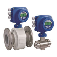
JUMO flowTRANS MAG H01 Operating Manual (260 pages)
Electromagnetic flowmeter for the process industry and hygienic applications
Brand:
JUMO
| Category:
Measuring Instruments
| Size: 14.89 MB
Table of Contents
Table of Contents
3
1 Safety
9
General Information and Notes for the Reader
9
Other Applicable Device Documentation
9
Intended Use
10
Improper Use
10
Target Groups and Qualifications
10
Warranty Conditions
10
Symbols and Signal Words
11
Nameplate
12
Transport Safety Information
17
Safety Information for Mounting
17
Safety Information for the Electrical Installation
18
Safety Information for Operation
18
Technical Limit Values
19
Admissible Measurement Media
19
Safety Information for Inspections and Maintenance
20
Returning Devices
20
Integrated Management System
21
Disposal
21
2 Design and Function
23
Measuring Principle
23
Device Versions
24
Device Designation
24
Type Series
24
Areas of Application
24
Functionalities
25
Design
26
Compact Design Type
26
Remote Mount Design Type
26
Housing Design Type
27
Explosion Protection
27
Overview of Device Versions
28
JUMO Flowtrans MAG S/H - Compact Design
28
JUMO Flowtrans MAG S/H - Remote Mount Design
29
3 Transport and Storage
31
Checking the Delivery
31
Transporting Flanged Devices
31
Flange Devices up to DN 400
31
Flange Devices Greater than DN 400
32
Storage
32
Nominal Widths Greater than DN 400
32
4 Mounting
33
General Information
33
Selecting Seals
33
Devices with a Wafer Design
34
Installing the Measuring Pipes
34
Tightening Torques
35
JUMO Flowtrans MAG S/H - Flanged/Connection Flange Design
35
JUMO Flowtrans MAG H - Variable Process Connections
40
Mounting
41
Flow Direction
41
Electrode Axis
41
Inlet Section, Outlet Section
41
Vertical Flow Direction
42
Horizontal Flow Direction
42
Free Inlet, Free Outlet
42
Heavily Contaminated Measurement Media
42
Installation Near Pumps
43
Minimum Clearance
43
Installation of the High-Temperature Version
43
Installation in Pipelines with Larger Nominal Widths
44
3A-Compliant Mounting
45
Devices with Advanced Diagnostics Functions
45
Notes on Opening and Closing the Housing
46
Rotation of the Transmitter Housing
47
Turning the LCD Display
47
Grounding
48
General Information
48
Metal Pipe with Fixed Flanges
48
Metal Pipe with Loose Flanges
49
Sensor Model 406015 and 406016
49
Plastic Tubes, Non-Metallic Tubes or Tubes with Insulating Lining
50
Grounding Devices with Protection Washers
50
Grounding with Conductive PTFE Grounding Washer
50
Devices with Advanced Diagnostics Functions
50
Installation and Grounding in Pipelines with Cathodic Corrosion Protection (CCP)
51
5 Electrical Connection
53
Installing the Signal and Magnet Coil Cable
53
Assembling the Signal and Magnet Coil Cable - Dual-Compartment Housing
54
Assembling the Signal and Magnet Coil Cable - Single-Compartment Housing
55
Sensor Connection
56
Metal Terminal Boxes
56
Protection Type IP68
57
Connection Via Cable Conduits
58
Potting the Terminal Box
59
Transmitter Connection
60
Voltage Supply Connection
60
Transmitter - Dual-Compartment Housing
61
Transmitter - Single-Compartment Housing
61
Signal and Magnet Coil Cable Connection
62
Connection Diagrams
63
HART, PROFIBUS-PA and FOUNDATION Fieldbus Protocol
63
Electrical Data
64
Current/Hart Output
64
Digital Output DO1
65
Digital Output DO2
65
Digital Input DI1
66
PROFIBUS-PA (PA+/PA-) / FOUNDATION Fieldbus (FF+/FF-) - According to IEC 61158-2
66
Connection Examples
66
Digital Output DO2
66
Digital Outputs DO1 and DO2
67
Digital Communication PROFIBUS-PA
67
6 Digital Communication
69
HART Protocol
69
System Integration
69
PROFIBUS-PA Protocol
70
System Integration
70
FOUNDATION Fieldbus (FF)
71
System Integration
71
7 Startup
73
Checks Prior to Start-Up
73
Configuring the Current Output
73
Transmitter - Dual-Compartment Housing
74
Transmitter - Single-Compartment Housing
75
Startup of PROFIBUS-PA Devices
76
Setting the Address Locally for Transmitters with a Dual-Compartment Housing
77
Configuration for Transmitters with a Single-Compartment Housing
78
Voltage/Current Consumption
79
System Integration
79
Startup for FOUNDATION Fieldbus Devices
80
Configuration for Transmitters with a Dual-Compartment Housing
81
Configuration for Transmitters with a Single-Compartment Housing
82
Setting the Bus Address
83
Starting up the Device
84
Loading the System Data
84
Error Message "Incompatible Sensor
85
Parameterization Via the "Easy Setup" Menu Function
86
Nominal Width, Measuring Range
92
8 Parameterization
95
Operation
95
Menu Navigation
95
Operating Key Function
95
Menu Levels
96
Process Display
97
Switch to the Information Level (Operator Menu)
98
Switching to the Configuration Level (Parameterization)
101
Hardware Write Protection
102
Selecting and Changing Parameters
103
Parameter Overview in the Configuration Level
105
Parameter Description
113
Menu: Easy Setup
113
Menu: Device Info
115
Menu: Device Setup
119
Menu: Display
123
Menu: Input/Output
125
Menu: Process Alarm
130
Menu: Communication
131
Menu: Diagnostics
136
Menu: Totalizer
145
Alarm Simulation
147
Filling Operation - JUMO Flowtrans MAG S02/H02
149
Configuration
150
9 Advanced Diagnostics Functions
153
General Information
153
Partial Filling Detection
153
Gas Bubble Detection
153
Electrode Coating Detection
154
Conductivity Monitoring
154
Electrode Impedance Monitoring
155
Sensor Measurements
155
Trend
155
Fingerprint
156
Checking the Grounding
156
Conducting the Grounding Check
156
Recommended Settings for Diagnostics Thresholds
158
Coil Resistance Thresholds
158
Electrode Coating Thresholds
159
Electrode Impedance Thresholds
159
Trend Logger
159
10 Error Messages
161
Calling up the Error Description
161
Error Statuses and Alarms
161
Error
161
Function Check
162
Operating the Device out of Spec
165
Maintenance
167
Overview of the Error Statuses and Alarms
167
Error Message During Startup
171
11 Maintenance
173
General Information
173
Sensor
174
Seals
174
Replacing the Transmitter or Sensor
175
Replacing the Sensor
175
Replacing the Transmitter
176
12 Spare Parts List
177
Transmitter Electronics Unit Fuse
177
Spare Parts for Devices with a Compact Design
177
Spare Parts for Devices with a Remote Mount Design
178
Field Housing
178
Sensor - Zone 2
179
Sensor - Zone 1
179
3A-Compliant Seal Materials
180
Flat Seals EPDM
180
Flat Seals Silicone
180
13 Technical Data
181
General Information
181
Reference Conditions According to en 29104
181
Maximum Measurement Deviation
181
Repeatability, Response Time
182
Sensor JUMO Flowtrans MAG S01/02
183
Temperatures
183
Storage Temperature
183
Minimum Admissible Pressure Depending on the Medium Temperature
183
Maximum Admissible Cleaning Temperature
183
Maximum Ambient Temperature Depending on the Medium Temperature
184
Protection Type According to en 60529
185
Pipe Vibration According to en 60068-2-6
185
Insertion Length
186
Signal Cable Length and Preamplifier
186
Sensor Materials
187
Process Connection Materials
189
Measuring Pipe Materials
189
Material Load on Sensor Housing
189
Sensor JUMO Flowtrans MAG H01/02
192
Temperatures
192
Storage Temperature
192
Minimum Admissible Pressure Depending on the Medium Temperature
192
Maximum Admissible Cleaning Temperature
192
Maximum Admissible Temperature Shock
192
Maximum Ambient Temperature Depending on the Medium Temperature
193
Protection Type According to en 60529
193
Pipe Vibration According to en 60068-2-6
193
Insertion Length
193
Signal Cable Length and Preamplifier
194
Sensor Materials
195
Material Load - Sensor Housing
196
Transmitter JUMO Flowtrans MAG 01
198
Electrical Properties
198
Electrical Isolation
198
Empty Pipe Detection
198
Mechanical Features
198
Temperatures
198
Protection Type According to en 60529
198
Vibration According to en 60068-2
199
Approvals/Approval Marks
200
14 Annex
209
Setting Parameter Overview (Default Setting)
209
With the PROFIBUS-PA Version
210
Approvals and Certifications
210
China Rohs
255
Advertisement
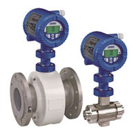
JUMO flowTRANS MAG H01 Safety Manual (58 pages)
Electromagnetic flowmeter for the process industry and hygienic applications
Brand:
JUMO
| Category:
Measuring Instruments
| Size: 6.37 MB
Table of Contents
Table of Contents
3
1 Safety
5
Obligations of the Operator
5
Other Applicable Device Documentation
5
Technical Limit Values
5
Safety Information for the Electrical Installation
5
Symbols and Signal Words
6
2 Device Versions
7
Device Designation
7
Explosion Protection
8
Housing Design Type
8
JUMO Flowtrans MAG S/H - Compact Design
9
Atex/Iecex Zone 1
9
Atex/Iecex Zone 2
9
JUMO Flowtrans MAG S/H - Remote Mount Design
10
Atex/Iecex Zone 1
10
Atex/Iecex Zone 2
11
Signal Cable Length and Preamplifier
12
Overview: the Fast Way to the Devices
13
Nameplate
14
Nameplate for Compact Design (Dual-Compartment Housing)
14
Nameplate for Compact Design (Single-Compartment Housing)
15
Nameplate for Remote Mount Design
16
Nameplate of the Transmitter (Dual-Compartment Housing)
17
Nameplate of the Transmitter (Single-Compartment Housing)
18
3 Mounting
19
Notes on Opening and Closing the Housing
19
Opening the Case Lid (Dual-Compartment Housing)
19
Opening the Case Lid (Single-Chamber Housing)
20
Rotation of the Transmitter Housing
20
Turning the LCD Display
21
Cable Inlets
21
Protection Type IP68
22
Notes on Using the Device in Areas with Combustible Dust
23
Maximum Admissible Surface Temperature
23
Minimum Signal Cable Length
23
Installation of the High-Temperature Version
24
4 Ex Relevant Data for Operation in Zones 1, 21 and 22
25
Electrical Connection
25
Sensor and Transmitter in Zone 1
25
Sensor in Zone 1 and Transmitter in Zone 2 or Outside of the Ex-Area
27
Electrical Data for Operation in Zones 1, 21, 22
29
Devices with HART Protocol
29
Devices with PROFIBUS PA or FOUNDATION Fieldbus
31
Temperature Data for Operation in Zone 1
33
5 Ex-Relevant Data for Operation in Zones 2, 21 and 22
39
Electrical Connection
39
Sensor and Transmitter in Zone 2 or Outside of the Ex-Area
39
Electrical Data for Operation in Zones 2, 21, 22
40
Devices with HART Protocol
40
Devices with PROFIBUS PA or FOUNDATION Fieldbus
41
Temperature Data for Operation in Zone 2
41
6 Startup
47
Checks Prior to Start-Up
47
Notes on Combinations of Sensors and Transmitters
47
Special Features of Device Version for Operation in Ex Zone 1
48
Configuring the Current Output
48
Configuring the Digital Output
48
7 Maintenance
51
General Information
51
Replacing the Transmitter or Sensor
52
Replacing the Sensor
52
Replacing the Transmitter
53
8 Annex
55
Approvals and Certifications
55
Advertisement
Related Products
JUMO flowTRANS MAG S01
JUMO flowTRANS MAG S02
JUMO flowTRANS MAG H02
JUMO flowTRANS MAG I02
JUMO flowTRANS MAG S10
JUMO flowTRANS MAG H10
JUMO flowTRANS MAG 01
JUMO flowTRANS MAG 02
JUMO flowTRANS MAG H20
JUMO meroVIEW 116
JUMO Categories
Transmitter
Measuring Instruments
Controller
Thermostat
Voice Recorder
More JUMO Manuals
Login
Sign In
OR
Sign in with Facebook
Sign in with Google
Upload manual
Upload from disk
Upload from URL