
Related Manuals for JUMO flowTRANS MAG I02


Summary of Contents for JUMO flowTRANS MAG I02
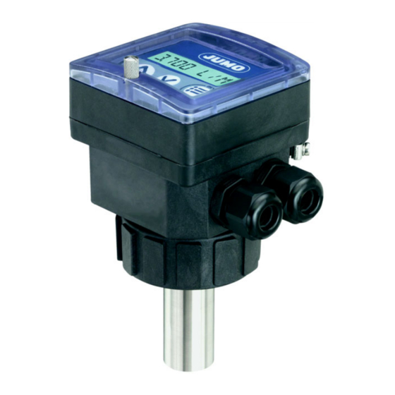
- Page 1 JUMO flowTRANS MAG I02 Electromagnetic flowmeter for liquids Operating Manual 40601100T90Z001K000 V3.00/EN/00690082...
-
Page 3: Table Of Contents
Contents Contents General information and notes for the reader ......6 Symbols and signal words ........... . . 7 Definition of terms . - Page 4 Contents 7.3.3 Terminal assignment and use of a selection switch ....... . . 26 7.3.4 Connecting the digital input DI1 .
- Page 5 Contents 9.5.1 Solving a problem with the device status LED ........76 9.5.2 Solving a problem without a warning or error message with the device status LED.
-
Page 6: General Information And Notes For The Reader
General information and notes for the reader 1 General information and notes for the reader Before mounting and starting up the unit, this manual must be read carefully. The manual is an integral part of the product and must be stored for subsequent use. In the interest of clarity, the manual does not contain all the detailed information about all product versions and cannot take into consideration every conceivable case involving the installation, operation or maintenance. -
Page 7: Symbols And Signal Words
1 General information and notes for the reader Symbols and signal words DANGER – Serious damage to health / risk to life! This symbol in connection with the signal word "danger" indicates an imminent threat of danger. Failure to observe the safety information results in death or serious injuries. WARNING –... -
Page 8: Intended Use
Intended use 2 Intended use NOTE! Failure to use this device correctly may pose a danger to people, surrounding machinery, and the envi- ronment. This device is intended solely for the purpose of measuring the flow rate of liquids. • During application, the admissible data and operating conditions specified in the legal documents and operating manual must be observed. -
Page 9: Basic Safety Information
Basic safety information 3 Basic safety information This safety information does not account for: • Random events or incidents that may occur during installation, operation, and maintenance of the device • Local safety requirements; the operator is responsible for compliance with any such regulations, in- cluding with regard to installation and maintenance specialists. - Page 10 3 Basic safety information NOTE! The device may be damaged by the medium. Systematically check the chemical compatibility of the materials used to make the device and the media with which the device comes into contact (for example: alcohols, strong or concentrated acids, alde- hydes, bases, ester, aliphatic compounds, ketone, aromatic or halogenated hydrocarbons, oxidizing agents, and chlorinated substances).
-
Page 11: General Information
In these cases, the manufac- turer's warranty no longer applies. Information available online NOTE! All the documentation, declarations of conformity and certificates are also available in the download area at www.jumo.de. -
Page 12: Design And Function
Design and function 5 Design and function General information 5.1.1 Design and function The device consists of a transducer (sensor) and a transmitter with a display. The transducer operates according to Faraday's law of induction. The flowmeter is equipped with an analog output (current output AO1, 4 to 20 mA), a digital output (tran- sistor output DO1, basic setting: pulse output), and two counters. -
Page 13: Nameplate
5 Design and function Nameplate Manufacturer and device designation Product group number Sensor version Part no. Conformity label Current/relay output data Barcode Fabrication number Voltage supply / digital input data (10) Flow direction... -
Page 14: Technical Data
Technical data 6 Technical data Measuring range and accuracy Flow velocity 0.2 to 10 m/s (0,66 to 32,8 ft/s) Measuring deviation with standard K-factor ≤ ±3.5 % of the measured value after Teach-In ≤ ±0.5 % of measured value Linearity ≤... -
Page 15: Mechanical Features
6 Technical data Mechanical features 6.3.1 Materials Housing/seal PPA, black/NBR Union nut Safety cap/seal PSU/silicone Front film Polyester M20 × 1.5 cable fittings/ PA/neoprene seal Screws Stainless steel Components in contact with the medium sensor Stainless steel 316 L (1.4404), FKM, or EPDM, PEEK Fitting ... -
Page 16: Electrical Data
6 Technical data Electrical data Voltage supply DC 18 to 36 V, filtered and regulated Tolerance of the applied voltage ±0,5 % Current consumption Max. 300 mA at DC 18 V Digital input DI1 Switching voltage DC 18 to 36 V Safety Protected against polarity reversal and voltage peaks, galvanically isolated Input impedance... -
Page 17: Connecting Cable
6 Technical data Connecting cable Connection type via two cable fittings M20 × 1.5 Cable data Cable type Shielded Cross-section 0.5 to 1.5 mm Cable diameter When using one cable per cable fit- 6 to 12 mm ting When using two cables per cable 4 mm, with supplied multiway seal fitting Environmental influences... -
Page 18: Mounting
Mounting 7 Mounting Safety information Risk of injury resulting from high pressure levels within the system! Before working on the system, switch off the pressure and bleed/empty the lines. Risk of electric shocks! Restrict the maximum operating voltage to DC 35 V if the unit is used in a humid environment or out- doors. - Page 19 7 Mounting Risk of injury due to improper startup! Failing to operate the device correctly can lead to injury and damage to the device and its surroundings. Prior to startup, make sure that the operating staff are familiar with and understand the contents of the operating manual.
-
Page 20: Installation Into The Pipeline
7 Mounting Installation into the pipeline Risk of injury resulting from high pressure levels within the system! Before working on the system, switch off the pressure and bleed/empty the lines. Risk of injury resulting from the type of medium! When using dangerous media, always observe the specifications on the safety sheet and the relevant accident prevention regulations. - Page 21 7 Mounting Installation The device can be installed in either a horizontal or ver- Correct Incorrect tical pipeline. Make sure that: • The section of pipe around the sensor is always filled. • The direction of flow (arrow) points upwards when installing vertically.
-
Page 22: Installation In A Pipeline With G 2" Union Nut
7 Mounting 7.2.2 Installation in a pipeline with G 2" union nut NOTE! Please refer to the recommended installation type! See chapter 7.2 "Installation into the pipeline", page 20 and operating manual "Fittings for flow rate sensors" (406090) NOTE! To ensure more accurate measurements and good stability of the flow rate zero point, bring the sensor into contact with the measurement medium at least 24 hours prior to calibration. -
Page 23: Electrical Connection
7 Mounting Electrical connection Risk of electric shocks! Restrict the maximum operating voltage to DC 35 V if the unit is used in a humid environment or out- doors. Before working on the system or device, switch off the voltage and secure it so that it cannot switch on again. -
Page 24: Make Sure That The Potential Is Equal In The Installation
7 Mounting 7.3.1 Make sure that the potential is equal in the installation Measures for making sure the potential is equal in the installation (voltage supply device measure- ment medium): • Connect the various grounding points in the installation to make sure any difference in potential be- tween two grounding points is eliminated. -
Page 25: Use Of A Cable Holder
7 Mounting Wiring diagrams for potential equalization in metal pipelines Voltage supply If direct grounding is not possible, connect a capacitor with 100 nF/50 V between the voltage sup- ply's negative terminal and the ground. Metal pipeline Shielding on the supply cable 7.3.2 Use of a cable holder NOTE! -
Page 26: Terminal Assignment And Use Of A Selection Switch
7 Mounting 7.3.3 Terminal assignment and use of a selection switch HINWEIS! Galvanic isolation of relay outputs DO2 and DO3 Mixed switching of mains voltage AC 230 V and SELV or PELV voltage is not admissible due to the basic insulation between the relays! Terminal strip I out Current output AO1 (4 to 20 mA) - Page 27 7 Mounting Use of the sink selection switch (right) or source selection switch (left) CURRENT CURRENT SINK SOURCE SINK SOURCE Selection switch A is used to configure the 4 to 20 mA output as a source or sink. Use of the selection switch to lock or unlock the CONFIRM key OFF ON OFF ON Selection switch B is used to lock or unlock the...
-
Page 28: Connecting The Digital Input Di1
7 Mounting 7.3.4 Connecting the digital input DI1 Possible connection options for the digital input DI1 CURRENT Iout L+ L - PE P+ P- SINK SOURCE Supply PULSE 18...36 Vdc CURRENT Iout L+ L - PE P+ P- SINK SOURCE Supply PULSE 18...36 Vdc... -
Page 29: Connection For The Current Output Ao1
7 Mounting 7.3.5 Connection for the current output AO1 NOTE! For safety reasons, secure the cable with a conductive cable holder. The current output AO1 (4 to 20 mA) can be connected as a source or a sink. NOTE! Adjust switch A to "SOURCE". Connecting the current output AO1 (4 to 20 mA) as a source 300 mA CURRENT... -
Page 30: Connecting The Transistor Output Do1
7 Mounting 7.3.6 Connecting the transistor output DO1 NPN connection for the transistor output DO1 300 mA Iout L+ L - PE P+ P- Supply PULSE 18...36 Vdc If direct grounding is not possible, connect a capacitor with 100 nF/50 V between the voltage sup- ply's negative terminal and the ground. -
Page 31: Startup And Parameterization
Startup and parameterization 8 Startup and parameterization Safety information Risk of injury due to improper operation! Failing to operate the device correctly can lead to injury, and damage to the device and its surroundings. The device/system must always be operated by staff with a sufficient level of training. Make sure that the operating staff are familiar with and understand the contents of the operating manual. -
Page 32: Operating Levels
8 Startup and parameterization Operating levels The device's operating levels consist of a process level and configuration level. Level Functions Process level Extracting the flow rate measured by the device, the current value emitted at the 4 to 20 mA current output, and the values for the main counter and daily counter Extracting the daily counter Switching to the configuration level... - Page 33 8 Startup and parameterization Process level Configuration level 12.6 L/S > 5 s > 2 s 16.45 mA 87654 L > 5 s Parameters Test menu Information menu menu 231 L. LANGUAGE CAL AO1 MEAS.OVF UNIT CALIB 0 CAL.FAIL > 2 s K-FACTOR FLOW NEG.FLOW...
-
Page 34: Display, Navigation Keys And Status Leds
8 Startup and parameterization Display, navigation keys and status LEDs Digital display with eight digits (four numeric, four alphanumeric) CONFIRM key: To select the displayed function, to confirm settings Status LED for the relay DO3 (LED on = Contact closed) Status LED for the relay DO2 (LED on = Contact closed) To read messages, to scroll down through the functions, to select the digit on the left Device status LED ... -
Page 35: Using The Navigation Keys
8 Startup and parameterization Using the navigation keys You can... Button functions Move between the functions in a Next function: level or menu Previous function: Display the parameters menu at the same time for 5 seconds in the process level Display the test menu at the same time for 5 seconds in the process level Display the information menu... -
Page 36: Process Level Details
8 Startup and parameterization Process level details This level is active when the device is switched on. 12.6 L/S 0 L/S. A dot after the flow unit indicates that the CUT-OFF function is active. The displayed flow rate is set to 0 because the mea- sured flow rate is below the threshold value defined in the CUT-OFF parameter of the parameters menu,... -
Page 37: Parameter Menu Details
8 Startup and parameterization Parameter menu details 1. In order to access the parameters menu, press the keys at the same time for more than 5 seconds. This menu allows you to adjust the following device parameters: LANGUAGE Choosing the display language UNIT Choosing the flow rate unit, the number of decimals, and the unit the count- ers are displayed in... -
Page 38: Choosing The Display Language
8 Startup and parameterization 8.6.1 Choosing the display language. The menu is in English when switched on. LANGUAGE ENGLISH DEUTSCH FRANCAIS 1. Confirm the displayed language. The selected language is immediately ac- tive. ITALIANO ESPANOL UNIT 1. If you do not wish to change any further parameters, go to the END function in the parameters menu and press the key in order to save the settings and return to the process level. - Page 39 8 Startup and parameterization UNIT FLOW LIT/SEC 1. Choose the flow rate unit 2. Confirm LIT/MIN LIT/H M3/MIN M3/H US GAL/S AUTO 1. Choose the number of decimal places 2. Confirm US GAL/M DEC PT 3 US GAL/H DEC PT 2 IMP GA/S DEC PT 1 IMP GA/M...
-
Page 40: Entering The K-Factor For The Fitting (406090) Used
8 Startup and parameterization 8.6.3 Entering the K-factor for the fitting (406090) used The device calculates the medium's flow rate in the pipeline with the K-factor for the fitting (406090) used. You can enter the K-factor for the fitting used here. The device can also determine the K-factor in a cal- ibration procedure (Teach-In), ... -
Page 41: Determining The Fitting's K-Factor With A Calibration Procedure (Teach-In)
8 Startup and parameterization 8.6.4 Determining the fitting's K-factor with a calibration procedure (Teach-In) NOTE! Prior to Teach-In: Calibrate the flow rate zero point ( see chapter 8.7.2 "Calibrate the flow rate zero point", page 67). Check that the KW value for the sensor has not been changed ( see chapter 8.7.4 "Changing the sen- sor's KW value", page 70). - Page 42 8 Startup and parameterization Determining the fitting's K-factor with a Teach-In process in relation to a volume (TEACH V.) NOTE! The device starts using the new K-factor as soon as the function SAVE YES is confirmed when leaving the parameters menu. 1.
- Page 43 8 Startup and parameterization Determining the fitting's K-factor with a Teach-In process in relation to a flow rate (TEACH F.) NOTE! The device starts using the new K-factor as soon as the function SAVE YES is confirmed when leaving the parameters menu. 1.
-
Page 44: Configuring Outputs
8 Startup and parameterization 8.6.5 Configuring outputs OUTPUT see chapter 8.6.6 "Configuring current output AO1", page 45. PULSE see chapter 8.6.7 "Configuring the transistor output DO1 as a pulse output", page 46 HYSTERES. see chapter 8.6.8 "Configuring the transistor output DO1 to switch a load depending on two threshold values", page 47 WINDOW... -
Page 45: Configuring Current Output Ao1
8 Startup and parameterization 8.6.6 Configuring current output AO1 NOTE! The current output AO1 emits a 22 mA-signal when the device emits an error, even if the output is de- activated. The current output AO1 (4 to 20 mA) emits a signal, the value of which represents the flow rate mea- sured by the device. -
Page 46: Configuring The Transistor Output Do1 As A Pulse Output
8 Startup and parameterization 8.6.7 Configuring the transistor output DO1 as a pulse output If the transistor output DO1 is configured as a pulse output, a pulse is generated at this output each time a selected medium volume is reached. NOTE! The units of the displayed values and the values to be entered manually correspond to the values se- lected in chapter 8.6.2 "Choosing the flow rate unit, the number of decimals, and the counter display... -
Page 47: Configuring The Transistor Output Do1 To Switch A Load Depending On Two Threshold Values
8 Startup and parameterization 8.6.8 Configuring the transistor output DO1 to switch a load depending on two thresh- old values NOTE! The units of the displayed values and the values to be entered manually correspond to the values se- lected in chapter 8.6.2 "Choosing the flow rate unit, the number of decimals, and the counter display unit", page 38. - Page 48 8 Startup and parameterization Hysteresis mode The output switches when a threshold is reached: • When the flow rate increases, the output status changes when the high threshold X+ is reached. • When the flow rate decreases, the output status changes when the low threshold X- is reached.
- Page 49 8 Startup and parameterization Example of operating the transistor output DO1 with switching thresholds Flow High switching threshold Low switching threshold Hysteresis Not inverted mode DEL. = 0 s Inverted Not inverted DEL. = 2 s Inverted Window Not inverted mode DEL.
-
Page 50: Configuring The Transistor Output Do1 To Switch A Load When The Direction Of Flow Changes
8 Startup and parameterization 8.6.9 Configuring the transistor output DO1 to switch a load when the direction of flow changes NOTE! If the measured flow rate is in the range of the CUT-OFF flow rate ( see chapter 8.6.16 "Adjusting the CUT-OFF flow rate", page 63), the flow rate is regarded as zero and positive. -
Page 51: Configuring The Transistor Output Do1 To Switch A Load When The Device Generates A Warning
8 Startup and parameterization 8.6.10 Configuring the transistor output DO1 to switch a load when the device gener- ates a warning When the device generates a warning message, the device status LED is orange. The generation of a warning message can also be indicated by the switching of the transistor output DO1. -
Page 52: Configuring The Relay Outputs Do2 And Do3
8 Startup and parameterization 8.6.11 Configuring the relay outputs DO2 and DO3 NOTE! The units of the displayed values and the values to be entered manually correspond to the values se- lected in chapter 8.6.2 "Choosing the flow rate unit, the number of decimals, and the counter display unit", page 38. - Page 53 8 Startup and parameterization Configuring the relay outputs DO2 and DO3 to switch a load when the direction of flow changes NOTE! If the measured flow rate is in the range of the CUT-OFF flow rate ( see chapter 8.6.16 "Adjusting the CUT-OFF flow rate", page 63), the flow rate is regarded as zero and positive.
- Page 54 8 Startup and parameterization Configuring the relay outputs DO2 and DO3 to switch a load when the device generates a warning When the device generates a warning message, the device status LED is orange. The generation of a warning message can also be indicated by the switching of the transistor out- put.
-
Page 55: Configuring The Digital Input Di1
8 Startup and parameterization 8.6.12 Configuring the digital input DI1 The digital input DI1 allows one of the four following functions to be triggered remotely: INPUT DISABLE The digital input is not used with this option. CALIB.0 Configure the digital input to re- motely trigger the calibration of the flow zero point. - Page 56 8 Startup and parameterization Configuring the digital input DI1 to trigger flow rate zero point calibration NOTE! Calibrating the flow rate zero point, see chapter 8.7.2 "Calibrate the flow rate zero point", page 67 INPUT CALIB 0 INV YES INV NO 1.
- Page 57 8 Startup and parameterization Configuring the digital input DI1 to trigger calibration for the device's HOLD mode NOTE! Triggering of HOLD mode is ignored if the checking function for proper output response is active ( see chapter 8.7.3 "Checking proper response of the outputs", page 70). The HOLD mode is used to carry out maintenance work without interrupting the process.
- Page 58 8 Startup and parameterization Configuring the digital input DI1 to switch from a measured value to a replacement value NOTE! The replacement value is ignored if the checking function for proper output response is active ( see chapter 8.7.3 "Checking proper response of the outputs", page 70). NOTE! The units of the displayed values and the values to be entered manually correspond to the values se- lected in chapter 8.6.2 "Choosing the flow rate unit, the number of decimals, and the counter display...
- Page 59 8 Startup and parameterization Configuring the digital input DI1 to freeze the counters Hold Tot. mode enables maintenance work to be performed without interrupting the process. When the device is in Hold Tot. mode: • The counters do not increment any more (frozen). •...
- Page 60 8 Startup and parameterization Configuring the digital input DI1 to reset the daily counter NOTE! The daily counter remains at zero until the digital input switches again. INPUT RES. TOT. INV YES INV NO 1. Choose INV NO to trigger the in- put on the leading edge.
-
Page 61: Adjusting The Filter To The Measured Flow Rate
8 Startup and parameterization 8.6.13 Adjusting the filter to the measured flow rate This function enables you to dampen the following fluctuations in the transmission of measured values: • On the display • At the current output AO1 NOTE! If "fast" filtering has been selected and the flow rate changes by ±30 % (e.g., when switching the medium circulation on or off), the filter is deactivated: The new flow rate is emitted in non-filtered form. -
Page 62: Resetting Both Counters
8 Startup and parameterization Available filters Filter 0: Filter 3 Filter 6 Filter 9 measured flow rate Slower measurand output Faster measurand output 1. If you do not wish to change any further parameters, go to the END function in the parameters menu and press the key in order to save the settings and return to the process level. -
Page 63: Adjusting The Mains Frequency
8 Startup and parameterization 8.6.15 Adjusting the mains frequency This function enables the mains frequency to be adjusted so that the device can filter interfering signals in the supply voltage. NOTE! Always adjust this parameter, even if the device is supplied with direct current (DC). FREQUENC. -
Page 64: Setting Display Backlight And How Long It Stays On, Or Deactivating The Backlight
8 Startup and parameterization 8.6.17 Setting display backlight and how long it stays on, or deactivating the backlight This function allows • The brightness of the backlight to be activated and adjusted and an activation period to be selected after pressing a button; •... -
Page 65: Test Menu Details
8 Startup and parameterization Test menu details To access the test menu, press the keys at the same time for more than 5 seconds. This menu enables: CAL. AO1 The current output (4 to 20 mA) to be adjusted. CALIB.0 The flow zero point of the device to be calibrated. -
Page 66: Adjusting The Current Output Ao1
8 Startup and parameterization 8.7.1 Adjusting the current output AO1 This function allows for the adjustment of the signal values emitted at the analog output. CAL. AO1 OFFSET OF = 4.05 The transmitter generates a current of 4 mA. 1. Measure the current emitted at the 4 to 20 mA output using a multi- meter. -
Page 67: Calibrate The Flow Rate Zero Point
8 Startup and parameterization 8.7.2 Calibrate the flow rate zero point NOTE! Adjust these parameters in the following cases: • Before using the Teach-In for the K-factor • After performing maintenance work • If the measured flow rate is not zero, even though medium circulation has been stopped NOTE! Make sure there are no air bubbles in the pipeline. - Page 68 8 Startup and parameterization Calibrating the flow rate zero point via the digital input NOTE! see also chapter 8.6.12 "Configuring the digital input DI1", page 55 1. Charge the pipe. 2. Stop medium circulation. 3. Make sure the device status LED is green. 4.
- Page 69 8 Startup and parameterization Calibrating the flow rate zero point using the CALIB 0 function in the test menu 1. Charge the pipe. 2. Stop medium circulation. CALIB.0 CALIB.N CALIB.Y 1. Choose CALIB.Y. MEASURE / The device calibrates the flow rate zero point. FLOW CAL.FAIL The calibration of...
-
Page 70: Checking Proper Response Of The Outputs
8 Startup and parameterization 8.7.3 Checking proper response of the outputs This function can be used to test whether the outputs are responding according to the settings. NOTE! The counters are incremented according to the measured flow rate value and not according to the sim- ulated value. -
Page 71: Monitoring The Flow Rate In The Pipeline
8 Startup and parameterization 8.7.5 Monitoring the flow rate in the pipeline A problem in the process or with the sensor can be detected if the flow rate measurement is too low or too high. This function enables the medium flow rate to be monitored and a report to be triggered if the flow rate is too low or too high. -
Page 72: Information Menu Details
8 Startup and parameterization Information menu details NOTE! This menu is only accessible when the device status LED is orange or red. Meaning of a message see chapter 9.5.4 "Solving a problem with a warning or error message with the red device status LED", page 79 and chapter 9.5.5 "Solving a problem with a warning or error message with the orange device status LED", page 80. -
Page 73: Maintenance
Maintenance 9 Maintenance Safety information Risk of injury resulting from high pressure levels within the system! Before working on the system, switch off the pressure and bleed/empty the lines. Risk of electric shocks! Before working on the system or device, switch off the voltage and secure it so that it cannot switch on again. -
Page 74: Returning Devices
Returning devices NOTE! All documents important for the return as well as the return address of the manufacturer are available at http://reparaturdienst.jumo.info. NOTE! According to the EU Directive for hazardous materials, the owner of hazardous waste is responsible for its disposal or must observe the following regulations when shipping: All devices delivered to the manufacturer must be free of any hazardous materials (acids, alkalis, sol- vents, etc.). -
Page 75: Replace The Seal (Device With G 2" Union Nut)
9 Maintenance Replace the seal (device with G 2" union nut) NOTE! Do not scratch the seal's groove. Device Groove Union nut Seal Fitting (type 406090) 1. Unscrew the device's union nut. 2. Pull the device out of the fitting. 3. -
Page 76: Troubleshooting
9 Maintenance Troubleshooting 9.5.1 Solving a problem with the device status LED Device sta- Analog out- Digital outputs Displayed Meaning Measure tus LED put AO1 DO1/DO2/DO3 message 0 mA Low signal status PWRFAIL The voltage supply • Make sure that the volt- is too low. - Page 77 9 Maintenance Device sta- Analog out- Digital outputs Problem Measure tus LED put AO1 DO1/DO2/DO3 Regardless of 20 mA Depending on the The current output • Check the settings for the current out- the color switching thresh- emits a 20 mA sig- put, ...
-
Page 78: Solving A Problem Without A Warning Or Error Message With A Green Device Status Led
9 Maintenance 9.5.3 Solving a problem without a warning or error message with a green device status Device sta- Analog out- Digital outputs Meaning Measure tus LED put AO1 DO1/DO2/DO3 Green 4 to 20 mA Depending on The device is not •... -
Page 79: Solving A Problem With A Warning Or Error Message With The Red Device Status Led
9 Maintenance 9.5.4 Solving a problem with a warning or error message with the red device status Device sta- Analog out- Digital outputs Displayed Meaning Measure tus LED put AO1 DO1/DO2/DO3 message 22 mA Depending on the "ERROR3" The user settings •... -
Page 80: Solving A Problem With A Warning Or Error Message With The Orange Device Status Led
9 Maintenance 9.5.5 Solving a problem with a warning or error message with the orange device status Device sta- Analog out- Digital outputs Displayed Meaning Measure tus LED put AO1 DO1/DO2/DO3 message Orange 4 to 20 mA Switched PULS.OVF The value set for •... - Page 81 9 Maintenance Device sta- Analog out- Digital outputs Displayed Meaning Measure tus LED put AO1 DO1/DO2/DO3 message Orange 4 to 20 mA Switched DISP.OVF The measured flow • Change the unit or dec- rate display in the imal places in the UNIT process level is full function in the parame- and does not corre-...
-
Page 82: Spare Parts And Accessories
Spare parts and accessories 10 Spare parts and accessories Risk of injury or material damage due to unsuitable parts! Using the wrong accessories and unsuitable spare parts can cause injuries and damage to the device and its environment. Always use genuine accessories and genuine spare parts supplied by the manufacturer. Designation Part no. -
Page 83: Packaging And Transport
Packaging and transport 11 Packaging and transport NOTE! Transport damage! Failing to protect the device properly can cause damage during transport. Transport the device in an impact-proof packaging solution that is protected from moisture and contam- ination. Do not subject the device to temperatures outside of the admissible storage temperature range, see chapter 12 "Storage", page 84. -
Page 84: Storage
Storage 12 Storage NOTE! Incorrect storage can cause damage to the device! Store the device in a dry and dust-free environment! Device storage temperature range: -20 to +60 °C. -
Page 85: Disposal
Disposal 13 Disposal NOTE! Environmental damage caused by improper disposal The country-specific laws and regulations for handling and disposing of waste must be observed! NOTE! At the end of its service life, the device and any batteries present do not belong in the trash! -
Page 86: China Rohs
China RoHS 14 China RoHS... - Page 88 JUMO GmbH & Co. KG JUMO Instrument Co. Ltd. JUMO Process Control, Inc. Street address: JUMO House 6733 Myers Road Moritz-Juchheim-Straße 1 Temple Bank, Riverway East Syracuse, NY 13057, USA 36039 Fulda, Germany Harlow, Essex, CM20 2DY, UK Delivery address:...
Need help?
Do you have a question about the flowTRANS MAG I02 and is the answer not in the manual?
Questions and answers