
Subscribe to Our Youtube Channel
Related Manuals for JUMO flowTRANS US W01


Summary of Contents for JUMO flowTRANS US W01
- Page 1 JUMO flowTRANS US W01 Ultrasonic flowmeter for liquids Operating Manual 40605000T90Z001K000 V1.00/EN/00729317/2022-01-17...
- Page 2 Further information and downloads qr-406050-en.jumo.info...
-
Page 3: Table Of Contents
Contents Contents About this documentation ........5 Purpose. - Page 4 Contents Electrical connection ......... 18 Preparing the electrical connection.
-
Page 5: About This Documentation
About this documentation 1 About this documentation Purpose This documentation is part of the device and includes all information to ensure that it is used safely and as intended across all phases of the product lifecycle. If you do not follow the documentation and safety information, this may result in risk to life and damage to property due to improper use. -
Page 6: Safety
Safety 2 Safety Safe operation This device is built based on current state-of-the-art technology and is safe to use. The device has been tested and was shipped from the plant in perfect working order. If you do not follow the measures to ensure safe operation, this may result in risk to life and damage to property due to improper use. -
Page 7: Hazardous Materials
2 Safety Hazardous materials Using hazardous materials as a medium may result in abrasive and corrosive damage to components of the device that come into contact with the medium. The medium may leak and present a fire hazard and a risk to health. Carry out a risk assessment taking into consideration the safety data sheet for the hazardous substances concerned for mounting, operation, maintenance, cleaning, and disposal: •... -
Page 8: Device Description
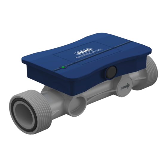
Device Description 3 Device Description Design Front view Rear view Meter run Device status LED Transducer (ultrasonic converter) O-ring (seal for the process connection) Housing for electronic components M12 plug connection (4-pole) Function The transducers are on opposite sides of the meter run and act as transmitters and receivers, i.e. they convert the electrical energy into sound waves and the sound waves into electrical energy. -
Page 9: Nameplate
3 Device Description Nameplate (6)(7) (12) (13) (2)(3) (14) 3 6 0 3 9 Fu l d a G e r m a n y (10) (11) Manufacturer and device designation Measuring range Product group number (10) Voltage supply Part no. Symbol for direct voltage) Fabrication number (11) -
Page 10: Technical Data
Technical data 4 Technical data Input 4.1.1 Measuring range and accuracy Nominal width Default settings for analog output Flow DN 15 (Low-flow calibration) 0 to 30 l/min 60 l/min DN 15 0 to 62.5 l/min 80 l/min DN 20 0 to 105 l/min 210 l/min DN 25 0 to 160 l/min... -
Page 11: Output
4 Technical data Output 4.2.1 Analog output Type Current output Function Output of the current flow rate, output of a signal for error messages, display via device status LED Signal range 4 to 20 mA Signal limits 3.8 to 20.5 mA Error message 3.4 or 22 mA (default settings: 3.4 mA) Temperature influence... -
Page 12: Electrical Data
4 Technical data Electrical data Voltage supply DC 18 to 30 V SELV, PELV, Class 2 Current consumption 50 mA, with digital output 300 mA Power consumption ≤ 10 W Protection rating DIN EN 61140, Class III (protective low voltage ) Electrical safety The device must be equipped with an electrical circuit that meets the require- ments of DIN EN 61010-1 with regard to "Limited-energy circuits". -
Page 13: Measurement Media
4 Technical data Measurement media Medium type Conductive or non-conductive liquids Viscosity ≤ 100 mPas Foreign matter content Solids ≤ 5 % vol Gases ≤ 1 % vol Medium temperature Temperature range -20 to +95 °C within the accuracy specifications -20 to +80 °C outside of the accuracy specifica- >... -
Page 14: Acceptance Of Goods, Storage, And Transport
5 Acceptance of goods, storage, and transport Scope of delivery 1× JUMO flowTRANS US W01 – Device in the ordered version, including test certificate 2× O-ring (seal for the process connection) in the ordered version 1× JUMO flowTRANS US W01 operating manual Checking the delivery •... -
Page 15: Installation
Installation 6 Installation Prepare installation Requirements: • Check the environmental influences to which the device will be exposed. • Switch off the plant's voltage and secure it so that it cannot switch on again. • Stop medium circulation in the plant. •... - Page 16 6 Installation Avoid mechanical strain Ensure that the center lines of both ends of the pipes align be- fore installing in the pipe (3). Align the ends of the pipes parallel and at an angle to one another. Adhere to the insertion length L of the device.
-
Page 17: Installing The Device
6 Installation Installing the device 1. Insert the O-rings supplied into the sealing ring grooves in the two process connections. 2. Install the device between the two union ends of the mounting set. Ensure that the O-rings (2) be- tween the process connections (1) and union ends (3) are cor- rectly positioned. -
Page 18: Electrical Connection
Electrical connection 7 Electrical connection Preparing the electrical connection Requirements: • Switch off the plant's voltage and secure it so that it cannot switch on again. • Correctly prepare the connections for the voltage supply and signal processing. The device must be equipped with an electrical circuit that meets the requirements of DIN EN 61010-1 with regard to "Limited-energy circuits". -
Page 19: Connection Of Analog Output
7 Electrical connection 7.1.2 Connection of analog output Current output – 4 to 20 mA +24 V ≤ 500 Ω Device Connecting cable Voltage output – 0 to 10 V (optionally) +24 V ≥ 700 Ω Device Connecting cable 7.1.3 Connection of digital output Requirements: •... - Page 20 7 Electrical connection Pulse output – push-pull (example 2) +24 V ≤ 200 mA, ≤ 10 kHz Device Connecting cable Pulse output – NPN (optionally) +24 V ≤ 200 mA, ≤ 10 kHz Device Connecting cable Pulse output – PNP (optionally) +24 V ≤...
-
Page 21: Connecting The Device
7 Electrical connection Connecting the device 1. Insert the connecting cable into the M12 plug connection. 2. Manually screw the union nut of the connecting cable onto the M12 plug connection on the de- vice. If you are using the connecting cable provided by the manufac- turer, tighten the union nut using an open-end wrench AF 13. -
Page 22: Operation
Operation 8 Operation Display and control elements Multicolored device status LED Troubleshooting The device status is indicated by a multicolored LED (red/green/yellow). LED signal Device status (error message) Status signal according to NAMUR Green (f = 1 Hz, t /T = 0.9) 0 = normal operation Red (f = 1 Hz, t /T = 0.5) -
Page 23: Maintenance And Cleaning
Maintenance and cleaning 9 Maintenance and cleaning Cleaning device housing The device housing can be cleaned when the device has been installed. Clean the device with a cloth dampened with water. Cleaning parts that come into contact with the medium and replacing O- rings Requirements: •... -
Page 24: Shutdown
• Decontaminate the device "Decontaminating the device", Page 23. 1. The supplementary sheet for product returns (http://productreturn.jumo.info) must first be completed correctly and signed. Then enclose it with the shipping documents and attach it to the packaging, ideally on the outside. -
Page 25: Accessories
Accessories 11 Accessories Product name Part no. Installation accessories Mounting set PVC DN 15 with PP-Nut 00750871 Mounting set PVC DN 20 with PP-Nut 00750872 Mounting set PVC DN 25 with PP-Nut 00750874 Mounting set PVC DN 32 with PP-Nut 00750876 Mounting set PP socket-welding DN 15 00750888... -
Page 26: China Rohs
China RoHS 12 China RoHS Product group: 406050 China EEP Hazardous Substances Information Component Name Hg ) Cr(VI) PBDE ○ ○ ○ ○ ○ ○ Housing (Gehäuse) ○ ○ ○ ○ ○ ○ Process connection (Prozessanschluss) ○ ○ ○ ○ ○... - Page 28 JUMO GmbH & Co. KG JUMO Instrument Co. Ltd. JUMO Process Control, Inc. Street address: JUMO House 6733 Myers Road Moritz-Juchheim-Straße 1 Temple Bank, Riverway East Syracuse, NY 13057, USA 36039 Fulda, Germany Harlow, Essex, CM20 2DY, UK Delivery address:...
Need help?
Do you have a question about the flowTRANS US W01 and is the answer not in the manual?
Questions and answers