Table of Contents
Advertisement
Quick Links
Advertisement
Table of Contents
Troubleshooting

Related Manuals for Covidien Puritan Bennett 560


Summary of Contents for Covidien Puritan Bennett 560
- Page 1 User’s Manual Puritan Bennett 560 Ventilator...
- Page 2 To obtain information about a warranty, if any, contact Covidien Technical Services at 1.800.635.5267 or your local representative. Purchase of this instrument confers no express or implied license under any Covidien patent to use the instrument with any ventilator that is not manufactured or licensed by Covidien.
-
Page 3: Table Of Contents
Contents Purpose of This Manual ..........Qualification of Personnel . - Page 4 Contents Oxygen ........... . 4–13 4.8.1 Administering Oxygen .
- Page 5 Contents B Modes of Ventilation ..........B–1 Modes of Ventilation .
- Page 6 This page intentionally blank. User’s Manual...
- Page 7 ECTION Figures ....... Figure 1-1. Locations of Labels – Top-Front View 1–16 .
- Page 8 Figures ......... . Figure 5-10.
- Page 9 ECTION Tables ..........Table 1-1.
- Page 10 This page is intentionally blank. viii User’s Manual...
-
Page 11: Purpose Of This Manual
Information regarding your product warranty is available from your sales representative or Covidien. Extended Service The Puritan Bennett™ 560 Ventilator offers extended service contracts/warranties for purchase when the ventilator is purchased. Please contact your local Covidien Sales or Service Representative for additional information. For online technical support, visit the SolvIT... -
Page 12: Technical Support
Preface Technical Support Technical Service Contacts: Covidien Argentina Covidien Australia Covidien Austria GmbH Aguero 351 52A Huntingwood Drive Campus21 Capital Federal - 1171 ABC, Huntingwood, NSW 2148 Europaring F09402 Argentina Australia Brunn am Gebrige Tel: (5411) 4863-5300 Telephone (+61) 1800 350702 A-2345 Österreich... - Page 13 Tel +34 93 475 86 69 Fax + 46 858 56 05 29 Fax +27 115 429 547 Fax +34 93 373 87 10 Covidien Switzerland Covidien UK & Ireland Covidien Singapore Roosstr. 53 Unit 2, Talisman Business Park Singapore Regional Service...
- Page 14 This page is intentionally blank. User’s Manual...
-
Page 15: Safety Information
1 Safety Information Definitions This manual uses three indicators to highlight critical information: Warning, Caution, and Note. They are defined as follows: Warning Indicates a condition that can endanger the patient or the ventilator operator. Warning Caution Indicates a condition that can damage the equipment. Note: Indicates points of particular emphasis, that make operation of the ventilator more efficient or convenient. - Page 16 If the ventilator fails the alarm tests or if you cannot complete the tests, refer to chapter “Troubleshooting” or call your equipment supplier or Covidien. • When an alarm condition is triggered, or there is evidence of a patient-ventilator fault or problem, examine the patient first before examining the ventilator.
- Page 17 41 °C (106 °F). This may lead to undesirable side effects for the patient. To avoid injury to the patient move the patient and the ventilator to a cooler location. For more information, contact Covidien. •...
- Page 18 Safety Information • The operator should connect the ventilator to an AC power source whenever available, for safer operation. • The maximum recommended shelf life of the internal battery is two (2) years. Do not use a battery that has been stored for two years prior to its first use. •...
- Page 19 Safety Information • The exhalation block is intended for single use by a single patient . It may periodically be cleaned, but it cannot be disinfected or sterilised. To maintain good measurement quality when used continuously, clean the exhalation block periodically (refer to section 7.3, “Cleaning the Exhalation Block”).
- Page 20 For more information, contact Covidien or your equipment supplier. • To connect the ventilator to a Nurse Call device, contact Covidien or your equipment supplier to check the ventilator's compatibility with the Nurse Call device and order a suitable connection cable.
- Page 21 • To ensure proper servicing and avoid the possibility of physical injury to personnel or damage to the ventilator, only personnel authorised and qualified by Covidien should attempt to service or make authorised modifications to the Puritan Bennett™ 560 Ventilator.
- Page 22 Do not attempt to open, repair or otherwise service the ventilator yourself. Doing so might endanger the patient, damage the ventilator, and/or void your warranty. Only personnel authorised and qualified by Covidien should repair, open or service the ventilator. •...
- Page 23 Safety Information • To connect the ventilator to an external power source, first ensure the ventilator’s I/O switch is off (O). Then, connect the desired power cable to the ventilator. Finally, connect the power cable to the external power source. •...
- Page 24 The use of any accessory other than those specified, with the exception of the power supplies or cables sold by Covidien, may lead to an increase in electromagnetic emissions or a decrease in the equipment protection against electromagnetic emissions. If the ventilator is used adjacent to such accessories or stacked with such devices, the ventilator’s performance should be monitored...
-
Page 25: Symbols And Markings
Safety Information Symbols and Markings Table 1-1. Ventilator Symbols Symbols Descriptions It is essential to read, understand, and follow these instructions before using the Puritan Bennett™ 560 Ventilator (ISO 7000-0434A). This symbol appears on the ventilator’s back panel, see Table 1-2, item 5. - Page 26 Safety Information Table 1-1. Ventilator Symbols (Continued) Symbols Descriptions This symbol appears on the ventilator’s front panel ALARM CONTROL key; see Figure 2-3 on page 2-6, item 3. (See my notes, to the left and below, in red). This key is used to: cancel the audible portion of alarms for 60 seconds at a time; cancel an alarm. For more information, refer to section E, “Alarms Tests.”...
- Page 27 Safety Information Table 1-1. Ventilator Symbols (Continued) Symbols Descriptions Flow shape (“flow distribution shape”, inspiratory phase) parameter. These symbols appear on the ventilation mode menu screens; selectable for V A/C mode only. For more information, refer to chapter 5, “Operating Procedures”.
- Page 28 This symbol indicates a communications port for interfacing with a USB connector. Figure 2-2, item 11. PC connector. This symbol indicates a port that can be used by authorised Covidien product service personnel or Covidien service personnel for software maintenance. See Figure 2-2, item 10.
-
Page 29: Labels / Identification And Instruction Information
Safety Information Labels / Identification and Instruction Information Various labels or specific markings are affixed to the ventilator that describe precautions to be taken for the correct use of the ventilator and contribute to the traceability of the product. Refer to Table 1-2 and the figures on the following pages for illustrations of these labels and markings and their locations on the... -
Page 30: Figure 1-1. Locations Of Labels - Top-Front View
Safety Information Table 1-2. Ventilator Labels and Markings (Continued) 13. FIO Label (Figure 1-1, Figure 1-4) Note: The item number callouts in the following figures refer to those listed in Table 1-2. Figure 1-1. Locations of Labels – Top-Front View 1-16 User’s Manual... -
Page 31: Figure 1-2. Locations Of Labels - Front-Left View
Safety Information Figure 1-2. Locations of Labels – Front-Left View Figure 1-3. Location of Labels and Markings – Rear View User’s Manual 1-17... -
Page 32: Figure 1-4. Location Of Labels - Bottom View
Safety Information Figure 1-4. Location of Labels – Bottom View 1-18 User’s Manual... -
Page 33: Ventilator Overview
2 Ventilator Overview Indications for Use The Device name is indicated for the continuous or intermittent mechanical ventilatory support of patients weighing at least 11 lb (5 kg) who require mechanical ventilation. The ventilator is a restricted medical device intended for use by qualified, trained personnel under the direction of a doctor. It is essential to read, under- stand, and follow these instructions before using the Puritan Bennett™... -
Page 34: Contraindications
Ventilator Overview Target Operators The ventilator may be operated by: • Respiratory therapists • Doctors • Nurses • Homecare providers • Patient and patient’s families Warning This ventilator must be used only under the responsibility and on the prescription of a doctor. Contraindications This ventilator is not for use with anesthetic gases, and is not intended for use as an emergency transport ven- tilator. -
Page 35: Device Classification
Ventilator Overview Warning Users must always possess an additional breathing circuit and exhalation valve while using the Device name. Device Classification The ventilator’s IEC / EN 60601-1classification is as follows: • Protection/Insulation class (electric shock): Class II • Protection index of enclosure: IP31 •... -
Page 36: Front Panel
Ventilator Overview Front Panel LCD Display – Displays information about the ventilator Exhalation Valve Port – Nipple for providing piloting including patient hours and software version, ventilation pressure to the exhalation valve. Controls the open-closed modes and settings, and monitored and calculated patient position of the exhalation valve. -
Page 37: Back Panel
Ventilator Overview Back Panel Ergonomic carrying handle. PC Cable Connector: USB mini-B connector used for Puritan Bennett™ Ventilator Test Software. On/Off (I/O) switch with protective cover: Inlet Port: Device powered on in position I; device Connects the ventilator to a low pressure oxygen switched off in position 0. -
Page 38: Control Panel
Ventilator Overview Control Panel Alarm indicators (two LEDs): DOWN/FREEZE key: • Red indicator: Moves the cursor down and decreases parameter values. • • During ventilation, freezes displayed waveform in the Continuous: Very High Priority (VHP) alarm Waveform menu. activated • High priority (HP) alarm activated. -
Page 39: Ventilation Menu
Ventilator Overview Ventilation Menu Ventilation menu with ventilation on standby. Ventilation menu during ventilation. General information line: Ventilation settings: Preferences menu access Displays the current ventilation mode, line: Displays the specific ventilation along with the following: parameter values for the Highlight this line and press •... -
Page 40: Alarm Menu
Ventilator Overview Alarm Menu Alarm menu with ventilation on standby. Alarm menu when not in standby. Title line: Alarm settings: Access line to Alarm Logs menu. Displays ventilation mode and the Displays the specific alarm parameter following symbols: values for the currently selected Highlight this line and ENTER ventilation mode, which are:... -
Page 41: Waveforms Menu
Ventilator Overview 2.10 Waveforms Menu The display of waveforms (Figure 2-6) is optional and can be selected using the Menu key The Wave- form menu is only accessible when ventilation is active. Title line: Graphic zone: Numeric zone: • Displays ventilation mode and the Displays the patient’s pressure and Displays monitored data. -
Page 42: Usb Memory Device Menu
Keep in mind that troubleshooting information is available in this manual to assist you in the event of a prob- lem. Refer to chapter 3, “Alarms and Troubleshooting”. If you cannot determine the cause of a problem, contact your equipment supplier or Covidien. Refer to chap- 8.3, “Service Assistance” 2-10 User’s Manual... -
Page 43: Alarms And Troubleshooting
3 Alarms and Troubleshooting Warning Setting Alarm limits to extreme values can cause the ventilator alarms to malfunction. When an alarm condition is triggered, or there is evidence of a patient-ventilator fault or problem, examine the patient first before examining the ventilator. Note: Many of the functions of the ventilator are not accessible when the Locking key is enabled. -
Page 44: Alarm Level Of Priority
Alarms and Troubleshooting Alarm Level of Priority The alarm hierarchy for signalling the level of alarm criticality is listed below. • Very High Priority (VHP): Immediate critical situation; ventilation is impossible: Continuous Sound Signaling / With or Without Continuous Red LED Illumination / With or Without Message / With or Without Display Lighting (it is possible for an alarm condition to occur that may not have both a message and lighting). -
Page 45: Alarm Display
Alarms and Troubleshooting Alarm Display During operation, when an alarm is activated: • One of the red or yellow alarm indicators to the left of the ALARM CONTROL illuminates and flashes. • An alarm tone sounds. • A message is displayed and flashes in reverse video at the bottom of the Ventilation Menu or Alarm Menu. -
Page 46: Alarm Logs Menu
Alarms and Troubleshooting Alarm Logs Menu All alarms are recorded in the internal memory of the ventilator at the time they are activated. The Alarm Logs menu is used to display the last eight (8) alarms activated, along with their date and time of activation. -
Page 47: Silencing The Audible Portion Of Alarms
Alarms and Troubleshooting To dismiss the Alarm Logs screen manually: Press the ENTER key when the cursor is on the “Back” line. The Alarm Logs screen is dismissed automatically: • After 15 seconds if no keyboard action is detected • When a High Priority alarm is triggered Note: Only qualified service personnel may access all alarms and events recorded by the ventilator. -
Page 48: Figure 3-5. Manually Pausing Alarms
Alarms and Troubleshooting Warning Alarm volume should be adjusted with respect to the ventilator’s operating environment and so that the patient's caretakers can hear the alarms. The audible alarm vents located at the front of the device should never be obstructed. The alarm can be paused with the Alarm Pause function by pressing the ALARM CONTROL key twice once the alarm has been declared. -
Page 49: Re-Activating Alarms
Alarms and Troubleshooting Re-activating Alarms Alarms that have been paused and whose activation conditions continue to exist can be reactivated. To reactivate alarms, proceed as follows: 1. Press the MENU key to access the Alarm Setting menu, if this is not the menu currently displayed. -
Page 50: Overview Of Alarms
Alarms and Troubleshooting Overview of Alarms Note: The message: “*IF PERSISTS RESTART/SRVC” will occur only if the alarm condition continues for longer than 30 seconds. Note: Many of the functions of the ventilator are not accessible when the Locking key is enabled. - Page 51 Alarms and Troubleshooting Table 3-1. Overview of Alarms (Continued) Audio Alarm Paused Paused Alarm Message Cause/Ventilator Response Priority Avail. Avail. Buzzer Battery Failure. The Battery BUZZER FAULT4 Buzzer Voltage is too low. RESTART/SRVC Internal technical problem that prevents the battery sounding the POWER SUPPLY LOSS alarm.
- Page 52 Alarms and Troubleshooting Table 3-1. Overview of Alarms (Continued) Audio Alarm Paused Paused Alarm Message Cause/Ventilator Response Priority Avail. Avail. Alarm activation occurs: CHECK Systematically after software • SETTINGS versions have changed. Loss of memorised parameters • Consequence: Locking Key disabled •...
- Page 53 Alarms and Troubleshooting Table 3-1. Overview of Alarms (Continued) Audio Alarm Paused Paused Alarm Message Cause/Ventilator Response Priority Avail. Avail. Internal battery capacity < 10 min. EMPTY BATTERY or 3%. (battery voltage < 22.5V) Consequence: ventilation comes to a halt. Abnormally high expired flow during EXH VALVE the inspiratory phase of three...
- Page 54 Alarms and Troubleshooting Table 3-1. Overview of Alarms (Continued) Audio Alarm Paused Paused Alarm Message Cause/Ventilator Response Priority Avail. Avail. Rate measured greater than HIGH RATE Max Rtot set during three consecutive breaths. Alarm activation occurs: After three consecutive breaths. •...
- Page 55 Alarms and Troubleshooting Table 3-1. Overview of Alarms (Continued) Audio Alarm Paused Paused Alarm Message Cause/Ventilator Response Priority Avail. Avail. Occurs in VALVE configuration when OCCLUSION the tidal volume is measured below CHECK CIRCUIT* 20ml during three consecutive breaths for PSV, CPAP, PA/C and P SIMV modes.
- Page 56 Alarms and Troubleshooting Table 3-1. Overview of Alarms (Continued) Audio Alarm Paused Paused Alarm Message Cause/Ventilator Response Priority Avail. Avail. Faulty internal pressure sensor PRES SENS FLT1 signal. RESTART/SRVC Alarm activation occurs: After 15 seconds. • Faulty proximal pressure sensor PROX SENS FLT2 signal.
-
Page 57: Troubleshooting
To ensure proper servicing and avoid the possibility of physical injury to personnel or damage to the ventilator, only personnel authorised and qualified by Covidien should attempt to service or make authorised modifications to the Puritan Bennett™ 560 Ventilator. - Page 58 Alarms and Troubleshooting Table 3-2. Alarms and Corrective Actions (Continued) Alarm Message or Symptom Possible Reason(s) For The Alarm Event Corrective Action(s) Restart ventilator to see if alarm clears. If Battery problem that prevents it from BATTERY FAULT1 not, replace the ventilator and call your operating.
- Page 59 Alarms and Troubleshooting Table 3-2. Alarms and Corrective Actions (Continued) Alarm Message or Symptom Possible Reason(s) For The Alarm Event Corrective Action(s) Obstruction or abnormal damage of the Clean or replace the exhalation valve and/or exhalation valve. its control tube. Remove moisture from exhalation block and valve.
- Page 60 Alarms and Troubleshooting Table 3-2. Alarms and Corrective Actions (Continued) Alarm Message or Symptom Possible Reason(s) For The Alarm Event Corrective Action(s) Operating speed of the cooling fan not Restart ventilator to see if alarm clears. If COOLING FAN properly adjusted for the internal ambient not, replace the ventilator and call your RESTART/SRVC temperature of the device.
- Page 61 Alarms and Troubleshooting Table 3-2. Alarms and Corrective Actions (Continued) Alarm Message or Symptom Possible Reason(s) For The Alarm Event Corrective Action(s) Note: Always consult the clinician before changing PEEP, FIO , pressure, volume or Rate settings. Check and properly connect the patient circuit connections.
- Page 62 Alarms and Troubleshooting Table 3-2. Alarms and Corrective Actions (Continued) Alarm Message or Symptom Possible Reason(s) For The Alarm Event Corrective Action(s) Note: Ensure that you are operating the ventilator within the proper temperature range (refer to Appendix A, “Specifications”). Put the device in a warmer environment (if the ambient temperature is too low) or in a cooler environment (if the ambient...
- Page 63 Alarms and Troubleshooting Table 3-2. Alarms and Corrective Actions (Continued) Alarm Message or Symptom Possible Reason(s) For The Alarm Event Corrective Action(s) Note: Always consult the clinician before Adjustment of Max PIP too low (only for changing PEEP, FIO , pressure, volume or V A/C and V SIMV modes).
- Page 64 Alarms and Troubleshooting Table 3-2. Alarms and Corrective Actions (Continued) Alarm Message or Symptom Possible Reason(s) For The Alarm Event Corrective Action(s) Note: Adjustment of the Max VTI level too low Always consult the clinician before (for PSV, CPAP, P A/C, P SIMV and V SIMV changing PEEP, FIO , pressure, volume or modes).
- Page 65 Alarms and Troubleshooting Table 3-2. Alarms and Corrective Actions (Continued) Alarm Message or Symptom Possible Reason(s) For The Alarm Event Corrective Action(s) Clean, unblock, and/or properly connect the Patient circuit obstructed. patient circuit. Check and properly connect the patient circuit connections. Leak in the patient circuit.
- Page 66 Alarms and Troubleshooting Table 3-2. Alarms and Corrective Actions (Continued) Alarm Message or Symptom Possible Reason(s) For The Alarm Event Corrective Action(s) OCCLUSION CHECK CIRCUIT Clean, unblock, and/or properly connect the Patient circuit obstructed. patient circuit. *IF PERSISTS RESTART/SRVC A non-vented configuration is being used or Replace the non-vented circuit with a the built-in leak in the mask or in the circuit vented one.
-
Page 67: Additional Troubleshooting
Alarms and Troubleshooting Table 3-2. Alarms and Corrective Actions (Continued) Alarm Message or Symptom Possible Reason(s) For The Alarm Event Corrective Action(s) Restart ventilator to see if alarm clears. If Defective inspiratory flow sensor or internal VTI NOT REACHED not, replace the defective device(s) and leak of the machine. - Page 68 Table 3-3. Additional Troubleshooting and Corrective Actions (Continued) Conditions Possible Causes Corrective Actions Replace the ventilator and call your Turbine noise. Light noise customer service representative. Filter and/or turbine silencer Replace the ventilator and call your deteriorated. customer service representative. Whistling noise or Replace the ventilator and call your Valve membranes damaged.
-
Page 69: Installation And Assembly
41 °C (106 °F). This may lead to undesirable side effects for the patient. To avoid injury to the patient move the patient and the ventilator to a cooler location. For more information, contact Covidien. -
Page 70: Connecting To External Ac Power
The use of any accessory other than those specified, with the exception of the power supplies or cables sold by Covidien, may lead to an increase in electromagnetic emissions or a decrease in the equipment protection against electromagnetic emissions. If the ventilator is used adjacent to such accessories or stacked with such devices, the ventilator’s performance should be... -
Page 71: Figure 4-1. The Power Cable Holder
Installation and Assembly that is inserted into the notch (Figure 4-1, item 2) of the battery cover: AC Power Cable Holder Figure 4-1. The Power Cable Holder To secure the AC power cable: 1. Insert the power cable holder (Figure 4-2, item 1) into the notch of the battery cover. -
Page 72: Connecting To An External Dc Power Source
Installation and Assembly • The AC POWER indicator on the top left corner of the ventilator illuminates. • The indicator flashes while the battery charges and then turns off when the battery is fully charged. Refer to Figure 4-4 on page 4-4. If the AC power cable becomes disconnected or the AC power source fails, an “AC POWER DISCONNEC- TION“... -
Page 73: Figure 4-5. Connecting The Ventilator To An External Dc Power Source
Installation and Assembly Note: An alternative means of ventilation should always be available, particularly when the patient is in transit or away from wall power. While using the ventilator on external battery power it is vital that a qualified caregiver (capable of providing necessary corrective actions in the event of alarm conditions) is present. -
Page 74: Patient Circuit
Installation and Assembly To connect the DC power cable to the ventilator: 1. Line up the red marker dot on the ventilator’s DC power connector with the marker on the DC power cable (Figure 4-6, item 1). Align the red markers (dots and/or lines) before connecting... -
Page 75: Choosing The Patient Circuit Type
To ensure proper performance of the ventilator, use a patient circuit recommended by Covidien in this manual; refer to chapter 4, “Installation and Assembly”... -
Page 76: Figure 4-7. Single Limb Patient Circuit With Exhalation Valve
Installation and Assembly See also NOTE: Although shown here, the Figure 4-9 humidifier (item 3), water trap page 4-9. (item 4), and tubes upstream of the single limb patient circuit are not included with the ventilator. Contact your supplier for more information. -
Page 77: Figure 4-8. Double Limb Patient Circuit
Installation and Assembly See also Figure 4-9 on page 4-9. Figure 4-8. Double Limb Patient Circuit Note: Although shown here, the humidifier (item 2), water traps (item 3), and their connecting tubes are not included with the patient circuit or ventilator. Contact your supplier for more information. Inhalation Port Exhalation Valve Tube... -
Page 78: Figure 4-10. Single Limb Patient Circuit Without Exhalation Valve
Installation and Assembly 5. Place a water trap (item 3) between the outlet port of the humidifier and the patient end. 6. Place a vented (NIV) interface to the end of the patient circuit. (item 5) Figure 4-10. Single limb Patient Circuit Without Exhalation Valve For both types of circuits, shown previously, you should connect the end of the proximal pressure tube as close as possible to the patient (at the mask or cannula entry, if possible) so that the ventilator can account for all load losses due to the circuit and its potential accessories. -
Page 79: Filters
Installation and Assembly Filters Warning Regularly check the cleanliness of the air inlet filter located on the rear of the ventilator. If necessary, replace the filter before the recommended replacement period is over (see chapter “Routine Maintenance”). This is particularly important when the ventilator is installed on a wheelchair, because environmental conditions may cause the filter to become dirty more rapidly. -
Page 80: Humidifier
Installation and Assembly • Connected to the FROM PATIENT port: This filter protects the internal exhalation flow sensor from the gases exhaled by the patient. Refer to Figure 4-8, item 10. Figure 4-12. Bacteria Filter Refer to the manufacturer’s instructions for more information about the use and maintenance of the bacteria filter(s). -
Page 81: Exhalation Block
Installation and Assembly water trap. If you notice any moisture in the patient circuit, you need to replace the wet circuit components with dry ones. Refer to the humidification device’s instruction for information on operating, cleaning, and sterilising the humidifier. Exhalation Block Warning The exhalation block is intended for single use by a single patient... -
Page 82: Connecting The Oxygen Supply
Installation and Assembly The Puritan Bennett™ 560 Ventilator can be used with an optional oxygen analyser with minimum and maximum concentration alarms. Always measure the delivered oxygen with a calibrated oxygen analyser (FIO kit) that features a minimum and maximum concentration alarm in order to ensure that the prescribed oxygen concentration is delivered to the patient. -
Page 83: Figure 4-16. Connecting The Oxygen Supply System
Installation and Assembly To connect the oxygen supply system to the ventilator: Refer to Figure 4-16 as required: 1. Inspect the oxygen supply’s connector (Figure 4-16, item 1) to ensure that connector’s black O-ring (item 2) is not missing. 2. Push the oxygen supply’s oxygen connector (item 1) into the ventilator’s oxygen connector (Figure 4-16, item 3). - Page 84 Installation and Assembly Warning The coupler must not remain connected to the oxygen connector unless it also connected to a leak-proof, external oxygen gas source. When an oxygen supply is not being used with the ventilator, disconnect the oxygen source completely from the ventilator. In the event of an oxygen leak, shut down the supply of oxygen at its source.
-
Page 85: Fitting The Ventilator Into The Dual Bag
Installation and Assembly Fitting the Ventilator into the Dual Bag The Dual Bag is a carrying bag with a dual function. It allows the Puritan Bennett™ 560 Ventilator to either be mounted onto a wheelchair or carried as a backpack. (see Figure 4-19) Warning... -
Page 86: Figure 4-19. Using The Dual Bag Accessory
Installation and Assembly Figure 4-19. Using the Dual Bag Accessory To install the Dual Bag onto a wheelchair do the following: 1. Unclip the two backpack straps from the side clips. 2. Clip the suspension belt onto the central ring. 3. -
Page 87: Mounting The Ventilator On The Utility Cart
Installation and Assembly 4.11 Mounting the Ventilator on the Utility Cart Match the mounting holes (item 1) on the bottom of the Puritan Bennett™ 560 Ventilator to the mounting studs (item 2) on the top of the utility cart platform. User’s Manual 4-19... -
Page 88: Connecting The Nurse Call Cable
Before using the Nurse Call system, ensure that its connections are secure and it operates properly. For more information, contact Covidien. To connect the ventilator to a Nurse Call device, contact Covidien to check the ventilator's compatibility with the Nurse Call device and order a suitable connection cable. -
Page 89: Operating Procedures
If the ventilator fails the alarm tests or if you cannot complete the tests, refer to section 3.8, “Troubleshooting” or call your equipment supplier or Covidien. Due to its limited internal battery’s reserve capacity, the ventilator should only be operated on the internal battery when no other power source is available. Ensure that the internal battery... -
Page 90: Figure 5-1. Turning On The Ventilator
Operating Procedures To turn the ventilator on: • Set the I/O switch (a covered, rocker-type switch located at the rear of the ventilator) to the I position, as shown in Figure 5-1 below. Figure 5-1. Turning on the Ventilator The following events occur: •... -
Page 91: Usb Menu Parameters
The USB Menu is not accessible from the Setup Menu or Maintenance menu. To access patient data via a PC, a dedicated software package, Puritan Bennett™ Respiratory Insight Software, is available for Clinicians. Contact Covidien or your Puritan Bennett™ product representative for further infor- mation. -
Page 92: Usb Menu
Operating Procedures 5.2.2 USB Menu To access the USB menu when a USB memory device is connected: Press the MENU key several times, until the USB Menu appears: Figure 5-4. Selecting the USB Menu In case of high priority alarm activation the ventilator will automatically display the alarm page. To return to the USB Menu, press the MENU key. -
Page 93: Transfer Trends
Operating Procedures • The cursor changes to the plus/minus symbol. • The parameter selected to be modified flashes. 3. Press UP or DOWN to change the selected parameter’s value. 4. Press ENTER to confirm the new parameter setting. • The new parameter setting is displayed continuously. •... - Page 94 Operating Procedures • The parameter selected to be modified flashes. 3. Press UP or DOWN to change the selected parameter’s value. 4. Press ENTER to confirm the new parameter setting. • The new parameter setting is displayed continuously. • The cursor is placed at the STOP position. 5.
-
Page 95: Starting Ventilation
Operating Procedures Starting Ventilation Before starting ventilation, refer to Appendix C, “Operational Verification Checklist”, and set the parameter values in the Preferences menu.) Warning Verify the functionality of the alarm conditions before connecting the patient to the ventilator. Before starting ventilation, ensure that the device is properly assembled and that the air inlet, cooling vents, and alarm sound diffusion holes are not obstructed. -
Page 96: Stopping Ventilation
Operating Procedures Front Panel Keyboard Figure 5-8. Starting Ventilation Stopping Ventilation Warning Do not allow a patient to remain connected to the ventilator when ventilation is stopped, because a substantial quantity of expiratory gas, primarily carbon dioxide, may be inhaled by the patient. -
Page 97: Turning Off The Ventilator
Operating Procedures • A new message appears that directs the user to press the key again to confirm ventilation stop. (shown in the graphic below). Figure 5-10. Stopping Ventilation (2) • A double “beep“ sounds. 3. Release the VENTILATION ON/OFF key. - Page 98 This page is intentionally blank. 5-10 User’s Manual...
-
Page 99: Internal Battery
6 Internal Battery Warning Even though the Puritan Bennett™ 560 Ventilator meets current safety standards, the internal Lithium-ion battery of the device exceeds the 100Wh threshold and is therefore considered to be Dangerous Goods (DG) Class 9 – Miscellaneous, when transported in commerce. As such, the Puritan Bennett™... -
Page 100: Battery Operation
Internal Battery Table 6-1. Internal Battery Reserve Capacity Displayed Values Average Operating Time on Internal Battery Power Vt 200 ml (± 5 ml) PIP 10 mbar (± 2 mbar) 11 hours (–10%) Rtot 20 bpm Vt300ml (± 5 ml) PIP ... - Page 101 Internal Battery Figure 6-1. Internal Battery Indicator • A loss of external supply alarm is activated. If ventilation is stopped, the internal battery reserve capacity is displayed as a percentage of battery charge. Refer to Figure 6-2. Figure 6-2. Battery Reserve Capacity as a Percentage If the ventilator is running, the internal battery reserve is momentarily displayed as a percentage.
-
Page 102: Testing The Battery
Internal Battery Warning Due to its limited internal battery’s reserve capacity, the ventilator should only be operated on the internal battery when no other power source is available. Ensure that the internal battery never becomes fully discharged. When the “LOW BATTERY“ alarm is triggered, immediately connect the ventilator to an AC power supply to maintain ventilation and recharge the internal battery. -
Page 103: Storage
Internal Battery • The “INTERNAL BATTERY“ indicator flashes (Figure 6-4, item 2). Figure 6-4. Power Indicators When Charging the Battery When the battery charge is complete, the “INTERNAL BATTERY“ indicator turns off. Warning Even if the “INTERNAL BATTERY“ indicator is off, charge of the battery may sometimes be incomplete regardless of charge time when the ambient temperature is above 40 °C (104 °F). - Page 104 Note: When the device is in storage it should be recharged monthly to maximise battery life. If the battery is stored for more than one month at a temperature greater than 21 °C (70 °F), or for more than one or two weeks at a temperature greater than 45 °C (113 °F), the reserve capacity of the battery may be affected.
-
Page 105: Cleaning
7 Cleaning Warning A patient treated by mechanical ventilation is highly vulnerable to the risks of infection. Dirty or contaminated equipment is a potential source of infection. Clean the ventilator and its accessories regularly and systematically before and after each use and following any maintenance procedure to reduce the risks of infection. -
Page 106: Cleaning The Accessories
Cleaning Table 7-1. Approved Cleaning Solutions for Exterior Ventilator Surfaces Description Mild dishwashing detergent 70% isopropyl alcohol (rubbing alcohol) 10% chlorine bleach (90% tap water) Glutaraldehyde Hospital disinfectant cleaners Hydrogen peroxide 15% ammonia (85% tap water) Ammonia-based household cleaners Household cleaners Cleaning the Accessories Follow the accessory manufacturer’s instructions for cleaning the ventilator’s accessories and components, including the patient circuit. -
Page 107: Routine Maintenance
Do not attempt to open, repair or otherwise service the ventilator yourself. Doing so might endanger the patient, damage the ventilator, and/or void your warranty. Only personnel authorised and qualified by Covidien should repair, open or service the ventilator. Replacing the Air Inlet Filter Warning Regularly check the cleanliness of the air inlet filter located on the rear of the ventilator. -
Page 108: Recommended Schedule Of Maintenance
Routine Maintenance b. The filter is properly installed in its housing. Proper installation of the filter prevents particles from entering the device. Figure 8-1. Replacing the Air Inlet filter Recommended Schedule of Maintenance Consumables and Replacement Intervals When used under normal circumstances - a relatively dust-free atmosphere, and without damage to the device and its components (shocks, cracks, significant dirt) - the intervals for replacing the ventilator’s consum- able elements are as follows: Table 8-1. - Page 109 Routine Maintenance Note: For all additional accessories not necessarily considered as consumables consult the manufacturer’s recommendations. To prevent any risk of cross contamination we recommend the use of DAR™ filters (Ref: 351/5856 or equivalent) to protect the patient outlet port and the exhalation block port. Warning Regularly check the cleanliness of the air inlet filter located on the rear of the ventilator.
-
Page 110: Service Assistance
In the event of a problem with the ventilator, refer to chapter 3, “Alarms and Troubleshooting”. If you cannot determine the cause of the problem, contact your equipment supplier or Covidien. For more information and local Covidien Technical Service Contact details, See “Technical Support”... -
Page 111: A Specifications
A Specifications Physical Table A-1. Physical Description (Excluding Accessories) Ventilator Weight 9.9 lb. (4.5 kg) Ventilator Dimensions 9.25 in wide x 12.40 in deep x 6.0 in high (235 mm wide x 315 mm deep x 154 mm high) Connectors Inspiratory limb connector: ISO 22 mm (OD) conical Exhalation limb connector (on exhalation block): ISO 22 mm (ID) conical... -
Page 112: Table A-3. Internal Lithium Ion Battery
Specifications Table A-3. Internal Lithium Ion Battery Voltage 25.2 VDC Full-load capacity 4.8 Ah Ampere-hour rating On standby: 1.5 Ah During ventilation: 0.5 Ah Watt hour rating 124Wh to 126Wh Charging current Standby mode 1.5 A/hr. (duration: < 6 hr.) •... -
Page 113: Indicators And Alarms
Specifications Indicators and Alarms Table A-5. Power Indicators Ventilation ON/OFF AC power DC power Internal Battery Blue in standby mode Green Green Flashing if the battery • • charge is in progress. Not lit if ventilation is in • progress. Continuously lit if the •... -
Page 114: Range, Resolution, And Accuracy
Specifications Table A-9. Monitored Parameter Tolerances (Continued) Ventilator Parameters Tolerances Exhalation Tidal Volume (VTE) ± (10 ml + 10%VTE)*VTE Total Breath Rate (Rtot) ± 1 bpm I:E Ratio (I:E) ± 50 ms or 10%, whichever is greater I/T Ratio (I/T) ±... - Page 115 Specifications Table A-10. Ventilator Range, Resolution, and Accuracy (Continued) Ventilator Settings Range, Resolution, and Accuracy Pressure support Range: OFF or 5 mbar to 55 mbar in valve configuration (P Support) Range: 6 mbar to 30 mbar in leak in valve configuration Resolution: 1 mbar Accuracy: ±...
- Page 116 Specifications Table A-10. Ventilator Range, Resolution, and Accuracy (Continued) Ventilator Settings Range, Resolution, and Accuracy PEEP Range: OFF (0.5 mbar) to 20 mbar Resolution: 1 mbar Accuracy: ± (1 mbar + 10%) mbar Default value: OFF Depends on: PIP in P A/C and PSV modes when Relative Pressure is set to YES Depends on: P Support and P Control in P SIMV mode when Relative Pressure is set to YES...
-
Page 117: Environmental
Specifications Table A-10. Ventilator Range, Resolution, and Accuracy (Continued) Ventilator Settings Range, Resolution, and Accuracy Minimum Peak Inspiratory Pressure Range: PIP- 20% (not adjustable in pressure breath) (Min PIP) Range: 2-52 in volume breath Resolution: N/A Maximum Peak Inspiratory Pressure Range: PIP+ 20 % (not adjustable in pressure breath) (Max PIP) Range: 12-60 in volume breath... -
Page 118: Usb
Specifications Table A-13. USB Memory Device Specifications Characteristics Supported formats USB compatibility USB flash memory USB 2.0 or USB 1.1 Memory file format USB 32 bit format (sector size: 512 - 2,048 bytes) Number of files Maximum 999 USB size 128 MB to 4 GB Table A-14. -
Page 119: Manufacturer's Declaration
Specifications A.10 Manufacturer’s Declaration The following tables, Table A-20 through Table A-23, contain the manufacturer’s declarations for the ventila- tor’s electromagnetic emissions, electromagnetic immunity, and recommended separation distances between the ventilator and portable and mobile RF communications equipment, as well as a list of compliant cables. Warning Portable and mobile RF communications equipment can affect the performance of the Puritan Bennett™... -
Page 120: Table A-21. Electromagnetic Immunity
Specifications Table A-21. Electromagnetic Immunity The ventilator is intended for use in the electromagnetic environment specified below. The customer or the user of the ventilator should ensure that it is used in such an environment. Electromagnetic Immunity Test IEC / EN 60601 Test Level Compliance Level Environment–Guidance Electrostatic discharge... -
Page 121: Table A-22. Electromagnetic Immunity - Conducted And Radiated Rf
Specifications Table A-22. Electromagnetic Immunity – Conducted and Radiated RF The ventilator is intended for use in the electromagnetic environment specified below. The customer or the user of the ventilator should assure that it is used in such an environment. IEC / EN 60601-1-2 Test Electromagnetic Environment–... -
Page 122: Table A-23. Recommended Separation Distances
Specifications Table A-22. Electromagnetic Immunity – Conducted and Radiated RF (Continued) Note: • At 80 MHz and 800 MHz, the higher frequency range applies. • These guidelines may not apply in all situations. Electromagnetic propagation is affected by absorption and reflection from structures, objects, and people. -
Page 123: Standards Compliance And Iec Classification
Specifications Table A-24. Compliant Cables and Accessories Cable or Accessory Maximum length UK AC power cable assembly 1.8 m (5.9 ft) Japan AC power cable assembly 1.8 m (5.9 ft) China AC power cable assembly 1.8 m (5.9 ft) South Africa AC power cable assembly 1.8 m (5.9 ft) India AC power cable assembly 1.8 m (5.9 ft) - Page 124 Specifications Particular Standards Lung Ventilators for Medical Use- Particular Requirements for Basic Safety and Essential • Performance Part 2: Home Care Ventilators for Ventilator-Dependent Patient EN ISO10651- 2:2009. Lung ventilators for medical use – Particular requirements for basic safety and essential •...
-
Page 125: B Modes Of Ventilation
B Modes of Ventilation Modes of Ventilation This chapter is a general description of the various modes of ventilation and breath types available with the Device name. Note: The default ventilation mode setting is P A/C; for more information, see below. B.1.1 Assist/Control (A/C) Modes When set to an Assist/Control mode, machine-initiated breaths are delivered at a clinician-set volume or pres- sure, inspiratory time, and rate. -
Page 126: Psv Mode
Modes of Ventilation B.1.4 PSV Mode PSV mode maintains a constant level of pressure in the patient’s airway during exhalation. In addition, the venti- lator applies a clinician-set pressure (Pressure Support) to each of the patient’s breaths. This has the same benefits as CPAP, with the additional benefit of assisting the patient in moving gas into his or her lungs. -
Page 127: C Operational Verification Checklist
• Following maintenance or changes in ventilator settings If the ventilator fails any of the safety checks below, or if you cannot complete these checks, refer to section 3.8, “Troubleshooting” or call the equipment supplier or Covidien (refer to section 8.3, “Service Assistance”). - Page 128 This page is intentionally blank. User’s Manual...
-
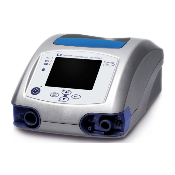
Page 129: D Unpacking And Preparation
Never use a ventilator or any components or accessories that appear to be damaged. If any signs of damage are evident, contact your equipment supplier or Covidien. 4. Clean the ventilator with a mild soap solution, if necessary (refer to chapter “Cleaning”). - Page 130 Unpacking and Preparation Figure D-1. Puritan Bennett™ 560 Ventilator Figure D-2. Dual Bag User’s Manual...
-
Page 131: E Alarms Tests
Troubleshooting section (refer to chapter 3, “Alarms and Troubleshooting”) of this manual or call your equipment supplier or Covidien (refer to section 8.3, “Service Assistance” The setting of the Min PIP alarm must be adjusted for the patient, but must also be set high enough to allow the PATIENT DISCONNECTION alarm to trigger properly. -
Page 132: Power Failure Test
Alarms Tests Power Failure Test Note: If the ventilator is operating on either the external power supply or the internal battery, you must plug it in to an AC power source before beginning this test. 1. Disconnect the ventilator from its AC power supply. Ensure that the following events occur: •... -
Page 133: Testing The Battery
Alarms Tests 7. Press and hold the VENTILATION ON/OFF key for three (3) seconds, then release it. Press the VENTILATION ON/OFF key again to confirm stop. • Ventilation stops. Testing the Battery The ventilator is capable of testing the power of the battery (refer to chapter 6, “Internal Battery”). - Page 134 This page is intentionally blank. User’s Manual...
-
Page 135: F Parts And Accessories
Table F-1 provides a list of accessories that are available for the Device name. To order parts or accessories, contact your equipment supplier or Covidien representative. Note: The ventilator is delivered with the following items: a printed User’s Manual, a CD with Clinician’s Manual (printed copy available upon request);... -
Page 136: Table F-2. List Of Circuits
Table F-2 provides a list of consumable parts available for the ventilator. Warning To ensure proper performance of the ventilator, use a patient circuit recommended by Covidien in this manual; refer to chapter 4, “Installation and Assembly” Appendix F, “Parts and Accessories”. -
Page 137: G Glossary
G Glossary AC Power Alternating current. Alarm Pause The audible and visual alarms cease and the symbol appears. The symbol will remain until the cause of the alarm is addressed. For example, when the ventilator is running on internal battery, the AC Disconnection alarm may be paused, and the alarm paused symbol will appear until the device is plugged into AC. - Page 138 Glossary Battery Level Display of the remaining battery capacity; located adjacent to the battery symbol. Bias flow Turbine flow during exhalation phase through the patient circuit to avoid rebreathing. An abbreviation for “breaths per minute,” which is the unit of measure for breath rate (see below). Breath Rate (Back Up R) The total number of breaths, both machine and spontaneous, delivered by a ventilator in one minute.
- Page 139 Glossary Fraction of Inspired Oxygen (FIO Amount of oxygen delivered to the patient. Sensor The sensor which measures the amount of oxygen being delivered to the patient. Flow Volume of gas delivered by the ventilator compared to time, expressed in litres per minute (lpm). Flow Pattern (Ramp Setting) This is the flow distribution shape during the inspiration phase.
- Page 140 Glossary Light Emitting Diode; used as indicator lights on the ventilator’s front panel. Litres Per Minute (a unit of volume flow rate). Machine Hours Counter for the total ventilation time since manufacture or the last CPU board change. Mains AC power supply. Max Leak The maximum alarm setting of a high leakage threshold.
- Page 141 Glossary Patient Counter Counter of ventilation time for the patient. Patient effort Inspiratory effort initiated by the patient. Patient circuit Tubing between the ventilator and the patient. Pause Waveforms freezing function. PAW (Peak Airway Pressure) The Peak Airway Pressure is the average peak pressure during the inspiratory phase, measured by each cycle and over the previous 24 hour period.
- Page 142 Glossary Rtot Parameter measured by the ventilator equal to the total number of breaths per minute (bpm). Sensitivity This adjustable parameter determines the amount of inspiratory effort required by the patient before the ventilator delivers an assisted breath, or demands flow in the case of a spontaneous breath.
- Page 143 Index DEVICE FAULT12....3-10, 3-18 DEVICE FAULT13....3-10, 3-18 AC power DEVICE FAULT3.
- Page 144 Index utilisation ......3-1 CONNECT VALVE OR CHANGE PRESS alarm message ventilation ......3-1 3-10, 3-17 Alarms tests Connecting to...
- Page 145 Index Front panel ......2-4 LOW VTl alarm message ... . 3-12, 3-23 Heat safety device, battery .
- Page 146 Index Physical specifications ....A-1 pneumatic......A-8 Placing the ventilator (installing) .
- Page 147 Index mounting on a wheelchair ... . . 4-17 mounting onto a utility cart ... . 4-19 parts and accessories ....F-1 patient outlet port connections (figure).
-
Page 148: Index
Index This page intentionally blank Index-6 User’s Manual... - Page 150 Part No. 10066883 Rev. B 03/2012 COVIDIEN, COVIDIEN with logo and Covidien logo are U.S. and/or internationally registered trademarks of Covidien AG. ™* Trademark of its respective owner. Other brands are trademarks of a Covidien company. ©2012 Covidien. Covidien llc, 15 Hampshire Street, Mansfield, MA 02048 USA.
Need help?
Do you have a question about the Puritan Bennett 560 and is the answer not in the manual?
Questions and answers