Table of Contents
Advertisement
Quick Links
Advertisement
Table of Contents

Related Manuals for Covidien Newport e360


Summary of Contents for Covidien Newport e360
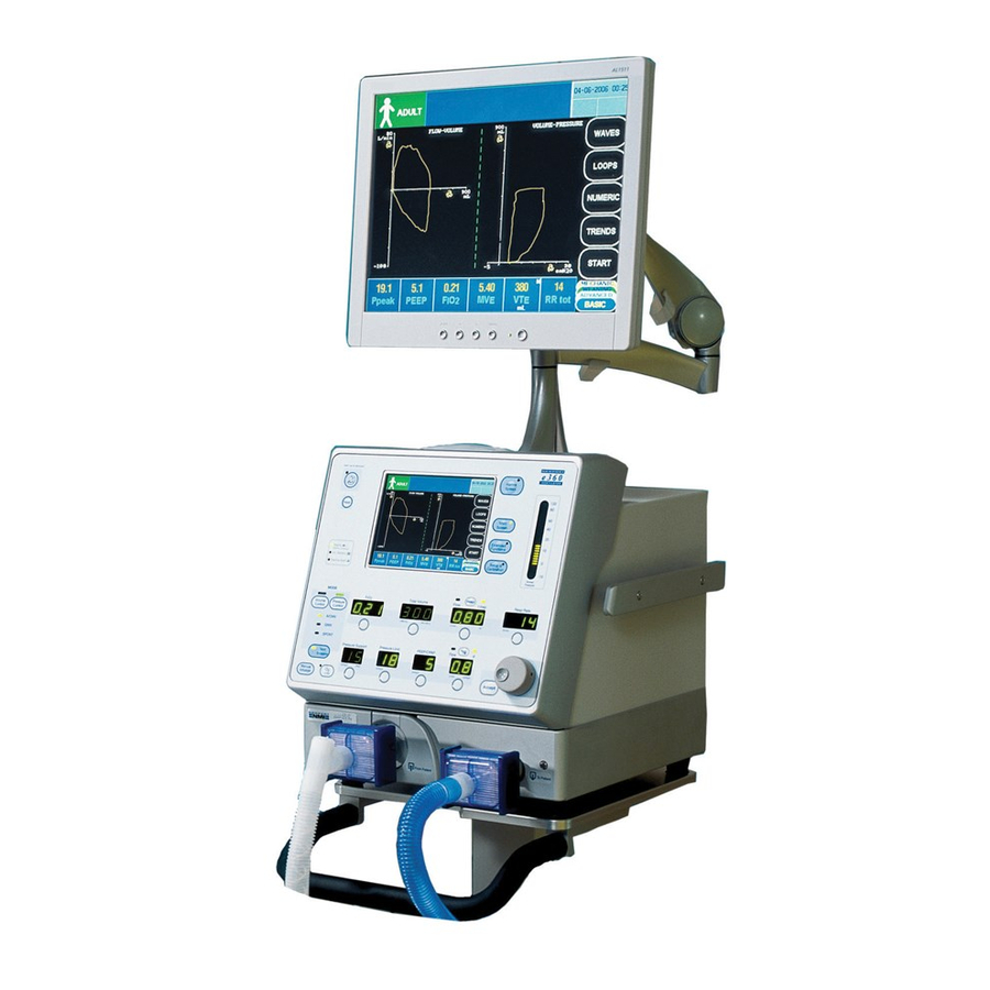
- Page 1 Service Manual Newport e360 Ventilator with Accessories...
- Page 2 © 2014, 2017, 2018, 2019 Covidien. All rights reserved. COVIDIEN, COVIDIEN with logo, and Covidien logo and Positive Results for Life are U.S. and internationally registered trademarks of Covidien AG. brands are trademarks of their respective owners. Other brands are trademarks of a Covidien company.
-
Page 3: Table Of Contents
Table of Contents Introduction Overview ..............1-1 Definitions . - Page 4 2.8.4 Exhalation Valve Adapter ............2-16 2.8.5 Exhalation Valve Diaphragm/Poppet Assembly .
- Page 5 4.12 Front Panel Cover (CVR2104M) ..........4-13 4.13 Optical Encoder (GR-ENC1800P) .
- Page 6 6.5.4 Loss of Gas Alarm ..............6-7 6.5.5 FiO2 Test .
- Page 7 Diagrams Index...
- Page 8 Page Left Intentionally Blank...
- Page 9 List of Figures Figure 2-1. Inlet Water Trap Filter Replacement............2-5 Figure 2-2. ...
- Page 10 Figure 4-17. Regulator and Solenoid Assembly (GR-BKT2105A) ........4-23 Figure 4-18. ...
- Page 11 List of Tables Table 1-1. Electromagnetic Emissions ..............1-5 Table 1-2. ...
- Page 12 Page Left Intentionally Blank viii...
-
Page 13: Overview
1 Introduction Overview It is very important to read and understand all of the information in this manual before attempting to service the Newport™ e360 ventilator. Please review all warnings and cautions in this manual before attempting to service the ventilator. Definitions Warnings, Cautions, and Notes 1.2.1... -
Page 14: General Warnings
Before returning to patient use, the ventilator must pass the operational verification procedure. WARNING: All ventilator service or repair must be performed by Covidien-trained service personnel. WARNING: Use extreme caution when working inside the ventilator while it is connected to a power source. -
Page 15: General Cautions
Use the tools specified in the manual to perform specific procedures. Service Guidelines Regular Service 1.6.1 Service must be provided at regular intervals by Covidien-trained service personnel who have received training specific to the maintenance and repair of the Newport™ e360 ventilator. Service Manual... -
Page 16: Complete Service Records
Covidien as replacements for internal components, may result in increased emissions or decreased immunity of the ventilator system. Covidien has no responsibility for the safe operation of the Newport™ e360 ventilator if the intended use, intended user, and intended use environment requirements specified in this document are not followed. -
Page 17: Table 1-1. Electromagnetic Emissions
Electromagnetic Compatibility (EMC) Note: These guidelines may not apply in all situations. Electromagnetic propagation is affected by absorption and reflection from structures, objects and people. Table 1-1. , Table 1-2. and Table 1-3. contain the manufacturer’s declarations for the ventilator system electromagnetic emissions, electromagnetic immunity, and a list of compliant cables. Table 1-1. Electromagnetic Emissions The ventilator is intended for use in the electromagnetic environment specified below. - Page 18 Introduction Table 1-2. Electromagnetic Immunity (Continued) Phenomenon Basic EMC standard or test Immunity test levels for professional method healthcare facility environment 30 A/m Rated power frequency IEC 61000-4-8 magnetic fields 50 Hz or 60 Hz 3 V rms. 0.15 MHz–80 MHz Conducted disturbances IEC 61000-4-6 induced by RF fields 6 V rms in ISM...
-
Page 19: Revision History
Covidien shall not be liable for errors contained herein or for incidental or consequential damages in connection with the furnishing, performance, or use of this material. -
Page 20: Contact Information
Contact Information 1.11 Technical Service Telephone: 1 800 255 6774, option #4 and option #2 Internet: www.covidien.com Email: venttechsupport@covidien.com Manufacturer Address:15 Hampshire Street, Mansfield, MA 02048 USA EC Representative: Covidien Ireland Limited, IDA Business and Technology Park, Tullamore, Ireland. Service Manual... - Page 21 Contact Information Covidien Service Centers: Covidien Argentina Covidien Asia Covidien Australia Covidien Austria GmbH Aguero 351 Singapore Regional Service 52A Huntingwood Drive Campus 21 Centre Capital Federal - 1171 ABC, Huntingwood, NSW 2148 Europaring F09402 Argentina 15 Pioneer Hub, #06-04...
- Page 22 Introduction Covidien Ireland Covidien Israel Covidien Italia S.p.A Covidien Japan Inc. Block G, Ground Floor, 5 Shacham St. Via S. Bovio 3 Technical Support Center Cherrywood Business Park, North Industrial Park S. Felice di Segrate (MI) 83-1, Takashimadaira 1- Chome Loughlinstown P.O.
- Page 23 Contact Information Covidien UK Covidien USA Unit 2, Talisman Business Park 2824 Airwest Blvd London Road, Bicester Plainfield, IN 46168 OX26 6HR [T] 1 800 255 6774 (option 4 & option 2) United Kingdom Email: venttechsupport@covidien.com [T] +44 0 1869 328 092...
- Page 24 Introduction Page Left Intentionally Blank 1-12 Service Manual...
-
Page 25: Maintenance, Overhaul, And Software Upgrade
2 Maintenance, Overhaul, and Software Upgrade Overview This chapter describes preventive maintenance, overhaul, and software upgrade procedures for use on the Newport™ e360 ventilator. Maintenance and Overhaul Intervals The level I preventive maintenance procedure should be performed once a year or every 5000 hours, whichever comes first. -
Page 26: General Cautions
Before returning to patient use, the ventilator must pass the operational verification procedure. WARNING: All service repairs of the ventilator must be performed by Covidien-trained service personnel. WARNING: To prevent damage from ESD and possible failure of the ventilator, use standard anti-static techniques when working inside the ventilator, handling circuit boards, or other electronic components. -
Page 27: Parts Required
Parts Required 5/64 in. hex key • Nonconductive tool for coin battery removal • USB-style keyboard • Parts Required Preventive Maintenance Kit 2.6.1 The preventive maintenance kit (PMK360A) includes the items listed in Table 2-1. Table 2-1. Preventive Maintenance Kit Parts List Part number Quantity Description JFK100P... -
Page 28: Overhaul Kit
Maintenance, Overhaul, and Software Upgrade Overhaul Kit 2.6.2 The overhaul kit (OVL360A) includes the items listed in Table 2-2. Table 2-2. Overhaul Kit Parts List Part number Quantity Description JFK100P JAR filter kit (oxygen and air for older models) KIT2103P Element & o-ring kit for water trap WTR2103P RRK1800M Regulator rebuild kit GRD1800P... -
Page 29: Maintenance Procedures
Maintenance Procedures Maintenance Procedures WARNING: Disconnect electrical power, air, and oxygen sources before attempting any disassembly. Inlet Water Trap Filters and O-Ring Assembly 2.7.1 Figure 2-1. Inlet Water Trap Filter Replacement Oxygen Filter To replace the oxygen filter, perform the following steps: Unscrew the collection bowl from the inlet water trap. -
Page 30: Exhalation Valve Adapter
Maintenance, Overhaul, and Software Upgrade Note: Ensure the o-ring is properly seated. Reinstall the filter holder. Reassemble the water trap assembly. Air Filter Note: If your air-side filter is the same as the oxygen filter, follow the steps in Oxygen Filter on page to change the... -
Page 31: Figure 2-3. Exhalation Valve Adapter Replacement
Maintenance Procedures Figure 2-3. Exhalation Valve Adapter Replacement Retaining latch Valve adapter To replace the exhalation valve adapter, refer to Figure 2-3. and perform the following steps: Access the exhalation valve adapter by lifting the retaining latch and removing the exhalation valve and exhalation flow sensor (see Figure 2-2. and Figure 2-3. ). To remove the silicone exhalation valve adapter, use your finger to grasp the adapter and pull it straight out. -
Page 32: Exhalation Valve Diaphragm, Seal, And O-Ring
Maintenance, Overhaul, and Software Upgrade Exhalation Valve Diaphragm, Seal, and O-Ring 2.7.3 Figure 2-4. Diaphragm, Seal, and O-Ring Replacement Exhalation valve nut collar (NUT1802M) Exhalation valve seal poppet (SEL1800M) Exhalation valve cap (CAP2112M) Silicone o-ring (ORG1200P) Diaphragm poppet assembly (PPT1805A) Exhalation valve body (BDY2103M) Exhalation valve cap poppet (CAP1803M) Exhalation valve slide (SLD2110M) Exhalation valve diaphragm (DIA1810M) -
Page 33: Emergency Relief Diaphragm
Maintenance Procedures Disassemble the diaphragm/poppet assembly by unscrewing it. To install the new DIA1810M and SEL1800M, reverse step 3. To reassemble the diaphragm/poppet assembly, exhalation valve cap, and exhalation valve nut collar, reverse steps 1 and 2. Locate and replace the o-ring (ORG1200P) inside the exhalation valve body (see Figure 2-4. ). Emergency Relief Diaphragm 2.7.4 Figure 2-5. Inhalation Outlet Assembly... -
Page 34: In-Line Disk Filters And Restrictor With Filter
Maintenance, Overhaul, and Software Upgrade Figure 2-6. Emergency Relief Diaphragm Replacement Outlet retaining screws Emergency relief diaphragm (DIA1800M) Inhalation adapter Emergency valve cap Inhalation outlet block To replace the emergency relief diaphragm, refer to Figure 2-5. and Figure 2-6. , and perform the following steps: Access the inhalation outlet assembly by removing the lower right front panel (see Figure 2-5. ). Remove the inhalation outlet assembly by removing the two retaining screws (see Figure 2-6. ). -
Page 35: Coin Battery (Sbc2100P And Sbc2108P)
Maintenance Procedures Note: If your ventilator does not have the in-line disk filters already installed, contact the Technical Service Department to obtain the necessary filter adapters. Coin Battery (SBC2100P and SBC2108P) 2.7.6 To replace the coin battery, perform the following steps: For first-time installation only: Locate JP1 on the SBC board and move the jumper from pins 2 and 3 to pins 1 and 2 (Figure 2-7. ). -
Page 36: Figure 2-9. Verifying The Time And Date
Maintenance, Overhaul, and Software Upgrade Turn on the ventilator, and wait for the CMOS error. Connect a USB keyboard, and then press F1. After the ventilator completes the power on, enter the correct date and time using the Technical Setup screen. Verify the time and date: Turn the ventilator off, allowing it to fully shut down. -
Page 37: Cooling Fan Filter And Guard
Maintenance Procedures Cooling Fan Filter and Guard 2.7.7 Figure 2-10. Filter and Guard Assembly Replacement Cooling fan filter and guard To replace the cooling fan filter and guard, refer to Figure 2-10. and perform the following steps: Pull off the filter guard. Remove the old filter and insert a new one. Replace the filter guard. -
Page 38: Inhalation Outlet Check Valve
Maintenance, Overhaul, and Software Upgrade Inhalation Outlet Check Valve 2.7.8 Figure 2-11. Inhalation Outlet Check Valve Inhalation outlet check valve To replace the inhalation outlet check valve, refer to Figure 2-11. and perform the following steps: Remove the mixing block by removing the two retaining screws (see Figure 2-13. ). Remove the inhalation adapter from the inhalation outlet assembly (see Figure 2-5. ). -
Page 39: Air And Oxygen Inlet Regulator Rebuild
Overhaul Procedures Air and Oxygen Inlet Regulator Rebuild 2.8.2 To remove and install the air and oxygen inlet regulator, follow the procedure in section 4.16.3, “Regulators, Inlet Blocks, and Flow Sensor Block.” Figure 2-12. Inlet Regulator Rebuild Cover Diaphragm Slip ring O-ring Spring ... -
Page 40: Cooling Fan Filter And Guard
Maintenance, Overhaul, and Software Upgrade Note: The regulator must be in a vertical position to reassemble the kit components. Ensuring all components are aligned, install the regulator brass cover and hand tighten. Note: This procedure is the same for both the air and the oxygen regulators. Cooling Fan Filter and Guard 2.8.3 To replace the cooling fan filter and guard, follow the procedure in section 2.7.7,... -
Page 41: Emergency Intake Diaphragm
Overhaul Procedures Emergency Intake Diaphragm 2.8.7 Figure 2-13. Emergency Intake Diaphragm and Valve Replacement Mixing block Mixing block retaining screws (2) Emergency intake valve assembly Emergency intake valve retaining screws (2) To replace the emergency intake diaphragm, refer to Figure 2-13. and perform the following steps: Remove the top cover by following the procedure in section 4.6, “Top Cover... -
Page 42: Inhalation Outlet Check Valve
Maintenance, Overhaul, and Software Upgrade Inhalation Outlet Check Valve 2.8.8 To replace the inhalation outlet check valve, follow the procedure in section 2.7.8, “Inhalation Outlet Check Valve.” In-Line Disk Filters and Restrictor with Filter 2.8.9 To replace the in-line disk filters and restrictor with filter, follow the procedure in section 2.7.5, “In-Line Disk Filters and Restrictor with Filter.”... -
Page 43: Figure 2-14. Location Of The Sbc Pcba, Coin Battery, And Internal Battery
Overhaul Procedures Figure 2-14. Location of the SBC PCBA, Coin Battery, and Internal Battery SBC2105A PCBA Internal battery positive and negative terminals Coin battery To avoid causing an electrical short circuit while removing the coin battery, use a nonconductive tool to push the battery out of its retainer on the SBC2105A. Capture the battery immediately as it comes out of the retainer and remove it from the ventilator. -
Page 44: Figure 2-15. Removing The Coin Battery
Maintenance, Overhaul, and Software Upgrade Figure 2-15. Removing the Coin Battery Slide the new coin battery (PT00055561) into the retainer (BH1), ensuring that the positive side of the battery is facing outward, away from the SBC board, as shown in Figure 2-16. Figure 2-16. Inserting a New Coin Battery Reconnect the internal battery positive (+) and negative (-) terminals. -
Page 45: Figure 2-17. Resetting The Time And Date
Overhaul Procedures Figure 2-17. Resetting the Time and Date Technical button Hour (hh), Minute (mm), Month (mm), Day (dd) & Year (yyyy) buttons Setup & Calibration key Verify the time and date: Turn the ventilator off, allowing it to fully shut down. After 30 seconds has elapsed, turn the ventilator back on. -
Page 46: Biannual Maintenance
Maintenance, Overhaul, and Software Upgrade Figure 2-18. Verifying the Time and Date Biannual Maintenance Internal Battery 2.9.1 Replace the internal battery at least every 2 years, or as needed to meet performance requirements. To remove and install the internal battery, follow the procedure in section 4.24, “Battery (BAT2100A).”... -
Page 47: Tubing
The tubing inside the ventilator does not need to be replaced at any predetermined time interval. However, Covidien is aware that tubing may occasionally need replacing. During the overhaul procedure, carefully inspect all tubing for degradation, cracks, or brittleness. If the tubing indicates any of those symptoms, contact Customer Service to order the Newport™... -
Page 48: Figure 2-19. Software Download / Diagnostics Mode Screen
Maintenance, Overhaul, and Software Upgrade When the Logo screen is displayed, release the Accept button. Wait for a few minutes until the Software Download/Diagnostics Mode screen is displayed (see Figure 2-19. ). Figure 2-19. Software Download / Diagnostics Mode Screen Connect the USB flash drive (with latest software) to the USB port on the back panel of the ventilator (see Figure 2-21. for USB port location). -
Page 49: Circuit Check Test And Diagnostic
Software Upgrade Procedure Confirm the software upgraded by checking the software version number (see Figure 2-20. , upper left corner). Figure 2-20. Event History Log Screen Remove the USB flash drive from the USB port on the back panel of the ventilator. Circuit Check Test and Diagnostic 2.10.3 ... -
Page 50: Figure 2-21. Back Panel Of Ventilator
Maintenance, Overhaul, and Software Upgrade Figure 2-21. Back Panel of Ventilator inlet Cooling fan filter Air inlet Power entry module USB connection Verify the medical-grade air source provides at least 30 psi, but does not exceed 90 psi. Connect the appropriate patient circuit to the ventilator, as shown in Figure 2-22. ... -
Page 51: Figure 2-22. Patient Circuit Setup
Software Upgrade Procedure Figure 2-22. Patient Circuit Setup Y-piece Breathing circuit Occlude the patient circuit using a cap (a filter and test lung are not required). Turn the ventilator back on. Wait until the Ventilation Standby screen appears. Follow the instructions that appear on screen, as shown in Figure 2-23. ... -
Page 52: Figure 2-23. Ventilation Standby Screen
Maintenance, Overhaul, and Software Upgrade Figure 2-23. Ventilation Standby Screen Touch the Circuit Check button to initiate the first step. The message “Circuit Check Test in Progress” is displayed, as shown in Figure 2-24. Figure 2-24. Circuit Check Screen When the first step is completed, remove the cap occluding the patient circuit y-piece, then touch the Circuit Check button again to complete the test. -
Page 53: Figure 2-25. Circuit Check Screen (Step 2)
Software Upgrade Procedure Figure 2-25. Circuit Check Screen (Step 2) When the circuit test is completed successfully, the message “Circuit Check PASSED” is displayed. If the circuit test failed, the message “Circuit Check FAILED” is displayed. Check the breathing circuit for leaks, and repeat the circuit check. If the circuit check fails again, contact the Technical Service Department for further assistance. -
Page 54: Figure 2-27
Maintenance, Overhaul, and Software Upgrade While the numbers are flashing, rotate the adjustment knob to change the altitude level as appropriate (for example, if located at sea level, set altitude to “0 m / 0 ft”). To confirm the selection, press Accept. Wait 15 seconds to 20 seconds. - Page 55 Software Upgrade Procedure Disconnect the medical-grade air source from the air inlet on the back panel of the ventilator. Disconnect the AC power cord from the AC wall outlet. If you have any questions, contact the Technical Service Department. Service Manual 2-31...
- Page 56 Maintenance, Overhaul, and Software Upgrade Page Left Intentionally Blank 2-32 Service Manual...
-
Page 57: Troubleshooting
This chapter provides information on troubleshooting the Newport™ e360 ventilator. Troubleshooting Guide Table 3-1. may provide guidance in determining the cause and possible corrective action for ventilator problems. Covidien does not guarantee that the suggested corrective action will solve the problem. Contact the Technical Service Department for additional assistance. - Page 58 Troubleshooting Table 3-1. Troubleshooting Guide (Continued) Problem Potential cause Suggested action Pressure relief valve regulator failure. Ventilator cannot achieve or Perform the operational verification maintain correct tidal volume, Crossover solenoid valve failure. procedure to diagnose the problem. Replace plateau pressure, or baseline any parts that may be defective.
-
Page 59: Device Alert Messages
Device Alert Messages Table 3-1. Troubleshooting Guide (Continued) Problem Potential cause Suggested action Monitored FiO values differ Defective oxygen sensor. Defective Replace the oxygen sensor. Replace analog analog board. board. from setting No audible alarm Defective alarm speaker, sound Replace alarm speaker or sound processor processor board, or SBC. - Page 60 Troubleshooting Table 3-2. Device Alert Messages (Continued) Device alert violation Violation message Priority level Definitions Control ROM failure Control ROM Failed High Read-only memory that stores the code of the control processor has an incorrect checksum. Control task continuity failure Control Tasks Failed High Software tasks of the control processor have operated out of sequence.
-
Page 61: Component Removal And Replacement
4 Component Removal and Replacement Overview This chapter provides procedures for removing and replacing various components of the Newport™ e360 ventilator. Key Components Ordering 4.2.1 To order a component, refer to Table B-1. for the appropriate part number. Note that Table B- 1. lists two part numbers for each component: a manufacturing part number and a service part number. -
Page 62: Exhalation Valve And Exhalation Flow Sensor
To avoid the possibility of electric shock, do not touch the power supply transformer when servicing the ventilator. WARNING: These instructions are intended for use only by Covidien-trained service personnel. Do not perform any unauthorized modifications or repairs to the ventilator or its components. Caution: To avoid damaging equipment, always use standard electrostatic discharge (ESD) precautions, including an ESD wrist strap, when servicing the ventilator. -
Page 63: Figure 4-1. Exhalation Valve And Exhalation Flow Sensor
Exhalation Valve and Exhalation Flow Sensor safe handling precautions and the ability to calibrate the sensor. Always make sure that the flow sensor is completely dry before installation. Figure 4-1. Exhalation Valve and Exhalation Flow Sensor Flow sensor cable (GR-CBL2123P) Flow sensor cable connection to connection to exhalation manifold exhalation flow sensor (FLS2101P) To replace the exhalation valve and exhalation flow sensor, refer to Figure 4-1. and perform the... -
Page 64: Exhalation Flow Sensor Cable (Outside) (Gr-Cbl2123P)
Component Removal and Replacement Exhalation Flow Sensor Cable (Outside) (GR-CBL2123P) 4.5.2 To replace the exhalation flow sensor cable, perform the following steps: Remove the exhalation valve and exhalation flow sensor by following the steps in section 4.5.1, “Valve (EXH2105A) and Flow Sensor (FLS2101P).”... -
Page 65: Front Panel Assembly
Front Panel Assembly To remove and reinstall the top cover, refer to Figure 4-2. and perform the following steps: Rotate the ventilator so the rear of the ventilator is facing you. Locate the six screws (three on each side) securing the cover to the ventilator and remove. Grab the handles on the sides of the ventilator, pull the sides away from the chassis, and slide the cover off of the ventilator. - Page 66 Component Removal and Replacement Locate and remove the following cables: GR-CBL2101A from J2 on GR-PCB2100A • GR-CBL2118A from J13 on GR-PCB2100A • GR-CBL2148A from J8 on GR-PCB2100A • PT00095462 from J10 on GR-PCB2100A • 10105498 air and oxygen PSOL valve cables from J705 (air) and J706 (oxygen) on GR-PCB2100A •...
-
Page 67: Main Board And Main Board Support
Main Board and Main Board Support Main Board and Main Board Support Main Board (GR-PCB2100A) 4.8.1 Figure 4-4. Main Board GR-CBL2137A and GR-CBL2138A Cable GR-CBL2112A to SBC2105A connected to P308 and P309 on GR-PCB2100A Screw and washer (one of four securing main LCD cable (GR-CBL2155A) board to main board support) GR-CBL212A connected to J4 on GR-PCB2100A... -
Page 68: Main Board Support (Cvr2103M)
Component Removal and Replacement Note: If the main board GR-PCB2100A is replaced, the ventilator software must be reloaded, and d1, d2, d4, and d9 calibrations performed. Refer to section 2.10 for the Software Upgrade Procedure and Chapter for calibration procedures. -
Page 69: Display Board (Gr-Pcb2109A)
Display Board (GR-PCB2109A) Note: Cable GR-CBL2137A connects from P308 on GR-PCB2100A to the top red LED. Cable GR-CBL2138A connects from P309 on GR-PCB2100A to the top amber LED. Display Board (GR-PCB2109A) Figure 4-6. Display Board (GR-PCB2109A) Screw (one of nine securing display board) GR-PCB2109A Encoder cable and J209 Service Manual... -
Page 70: Figure 4-7. Touch Screen Board (Pcb2105P) (Pcb2105P-M For E360T Model)
Component Removal and Replacement Figure 4-7. Touch Screen Board (PCB2105P) (PCB2105P-M for e360T Model) GR-CBL2147A (GR-CBL2149A for e360T Screw model) PCB2105P (PCB2105P-M for e360T Four-pin ribbon cable model) To replace the display and touch screen boards, refer to Figure 4-6. and Figure 4-7. , and perform the following steps: Remove the main board support by performing the steps in section 4.8, “Main Board and Main Board... -
Page 71: Touch Screen Interface Board (Pcb2105P) (Pcb2105P-M For E360T Model)
Touch Screen Interface Board (PCB2105P) (PCB2105P-M for e360T model) Touch Screen Interface Board (PCB2105P) (PCB2105P-M for 4.10 e360T model) To replace the touch screen board, refer to Figure 4-7. and perform the following steps: Remove the display board by performing the procedure in section 4.9, “Display Board (GR-PCB2109A).”... -
Page 72: Lcd Display (10139301)
Component Removal and Replacement To replace the LCD cable, refer to Figure 4.10 and perform the following steps: Remove the display board by performing the procedure in section 4.9. Using a 7/32 inch nut driver, remove the nut securing the ground wire of GR-CBL2155A to the LCD housing BKT2104M. -
Page 73: Front Panel Cover (Cvr2104M)
Front Panel Cover (CVR2104M) Front Panel Cover (CVR2104M) 4.12 Figure 4-9. Front Panel Cover (CVR2104M) Screw (one of eight securing cover) BZL2108M Nut securing flat ribbon ground cable Adjustment knob located on front panel CVR2104M Backlight inverter PCB To remove and reinstall the front panel cover, refer to Figure 4-9. and perform the following steps: Remove the display board by performing the procedure in section 4.9, “Display Board (GR-PCB2109A).”... -
Page 74: Optical Encoder (Gr-Enc1800P)
Component Removal and Replacement Optical Encoder (GR-ENC1800P) 4.13 To replace the optical encoder, perform the following steps: Remove the front panel cover by performing the procedure in section 4.12, “Front Panel Cover (CVR2104M).” Using an 11 mm wrench, remove the nut and washer securing the encoder to the front panel cover (CVR2104M). -
Page 75: Touch Screen (Gr-Pnl2105P)
Touch Screen (GR-PNL2105P) Touch Screen (GR-PNL2105P) 4.15 Figure 4-10. Touch Screen Panel (GR-PNL2105P) Inside edge of touch screen window BZL2108M TAP2100P Caution: Removal of the touch screen (GR-PNL2105P) will destroy the screen. Do not remove it unless you have a replacement touch screen. To replace the touch screen, refer to Figure 4-10. and perform the following steps: Remove the LCD display by performing the procedure in section 4.11, “Large LCD Cable and LCD... -
Page 76: Pneumatics Panel Assembly And Components
Component Removal and Replacement Pneumatics Panel Assembly and Components 4.16 Panel Assembly (SVO2101A) 4.16.1 Note: For China, the panel assembly part number is SVO2111A. To remove and reinstall the panel assembly, refer to Figure 4-11. , Figure 4-12. , and Figure 4-13. , and perform the following steps: Remove the top cover and front cover assembly by performing the procedure in sections 4.6, “Top Cover (CVR2101M)”... -
Page 77: Figure 4-12. Cover (Cvr2115M) And Gasket (Gkt2101M)
Pneumatics Panel Assembly and Components Figure 4-12. Cover (CVR2115M) and Gasket (GKT2101M) Remove the yellow tube and the blue tube from the air and oxygen inlet manifold (BLK2115M). Remove the four screws (two on each side) securing the pneumatics panel (PNL2102M). Service Manual 4-17... -
Page 78: Figure 4-13. Pneumatics Panel
Component Removal and Replacement Figure 4-13. Pneumatics Panel Screws (two of four securing PNL2102M) Remove the yellow tube and the blue tube from the air and oxygen PSOL valves by disassembling the luer lock connectors. While supporting the pneumatics panel, slide the panel away from the ventilator. To reinstall the panel assembly and components, perform the following steps: Supporting the pneumatics panel, align the air and oxygen flow sensors with the flow sensor manifold block. -
Page 79: Air And Oxygen Inspiratory Flow Sensors (Gr-Ftd2100P And Gr-Ftd2101P)
Pneumatics Panel Assembly and Components Air and Oxygen Inspiratory Flow Sensors (GR-FTD2100P and GR-FTD2101P) 4.16.2 Figure 4-14. Inspiratory Flow Sensors Mixing block (BLK2107M) Air flow sensor (GR-FTD2100P) Cable GR-CBL2116A connected to J1 on Oxygen flow sensor (GR-FTD2101P) flow sensors To replace the flow sensors, refer to Figure 4-14. ... -
Page 80: Regulators, Inlet Blocks, And Flow Sensor Block
Component Removal and Replacement Regulators, Inlet Blocks, and Flow Sensor Block 4.16.3 Figure 4-15. Pneumatics Panel Assembly Inlet regulator (REG1800P) PSOL valves Inlet block (BLK2115M) Back panel (PNL2102M) Flow sensor block (BLK2101M) Note: To replace the regulators, inlet blocks, or the flow sensor block, all screws securing the pneumatic assembly to the back plate must be removed. -
Page 81: Psol Valves (10113777)
Pneumatics Panel Assembly and Components Remove the two screws securing the flow sensor block to PNL2102M. Lift the assembly away from the panel (PNL2102M). Disassemble each component as needed. Reassemble by reversing steps 2 through 5. Note: Ensure the PSOL valves and regulators are aligned during reassembly. ... -
Page 82: Figure 4-16. Psol And Nylon String
Component Removal and Replacement Figure 4-16. PSOL and Nylon String Separate the PSOL from the pneumatic block. Replace the PSOL, making sure to verify the following occurs: The o-rings are free of particulates, which can cause leaks. • The nylon string is reinserted so that three inches of it protrudes from the PSOL. •... -
Page 83: Regulator And Solenoid Assembly (Gr-Bkt2105A)
Pneumatics Panel Assembly and Components Regulator and Solenoid Assembly (GR-BKT2105A) 4.16.5 Figure 4-17. Regulator and Solenoid Assembly (GR-BKT2105A) Screws securing GR-BKT2105A to ventilator Exhalation PSOL regulator (REG1701P) Exhalation PSOL valve (VLV1806P) Safety regulator (REG1802P) Emergency relief solenoid (SOL1501P) Crossover solenoid (SOL1501P) Machine 1 pressure rezero solenoid Regulator and solenoid assembly (SOL1501P) (GR-BKT2105A) -
Page 84: Main Flow Outlet Block (Gr-Blk2108A)
Component Removal and Replacement Remove the green tubing from the bottom port of the pressure transducer (XD106) (machine 2 pressure) on the analog board. Remove the green tubing from the exhaust port of the rezero solenoid for machine pressure 2. Remove the blue tubing from the exhalation PSOL valve (VLV1806P) and the tee connector. -
Page 85: Oxygen Sensor (Sen2103P)
Oxygen Sensor (SEN2103P) Figure 4-19. Outlet Block (BLK2108M) Outlet block Oxygen sensor cable (GR-BLK2108A) (GR-CBL2109A) Screws Pull BLK2108M away from the ventilator, and remove the two tubes. Reinstall the outlet block by reversing steps 2 and 3. Oxygen Sensor (SEN2103P) 4.18 Figure 4-20. Oxygen Sensor (SEN2103P) To replace the oxygen sensor, refer to Figure 4-19. and Figure 4-20. ,and perform the following steps: Remove the oxygen sensor cable (GR-CBL2109A) from the oxygen sensor (SEN2103P) by unscrewing the connector on the cable. -
Page 86: Inhalation Outlet Block And Mixing Block Assembly
Component Removal and Replacement Note: On older model ventilators, the oxygen sensor may be screwed in; if so, remove by turning it counterclockwise. Reinstall the oxygen sensor by reversing steps 1 and 2. Inhalation Outlet Block and Mixing Block Assembly 4.19 Figure 4-21. Inhalation Outlet Block and Mixing Block To remove and reinstall the inhalation outlet block and the mixing block, refer to Figure 4-21. and... -
Page 87: Analog Board (Gr-Pcb2110A)
Analog Board (GR-PCB2110A) Analog Board (GR-PCB2110A) 4.20 Figure 4-22. Analog Board (GR-PCB2110A) Flat cable (GR-CBL2118A) Screw and washer (one of four securing the board) Blue tube (XD103) Orange tube (XD107) Yellow tube (XD102) Green tube (XD106) Clear tube (XD105) Oxygen sensor cable (GR-CBL2109A) Flow sensor cables To replace the analog board, refer to Figure 4-22. and perform the following steps: Remove the regulator and solenoid assembly by performing the procedure in section 4.16.5,... - Page 88 Component Removal and Replacement Remove the following tubes from GR-PCB2110A: Orange tube (exhalation valve pressure from XD107) • Green tube (exhalation valve pressure from XD106) • Blue tube (regulated oxygen pressure from XD103) • Yellow tube (regulated air pressure from XD102) •...
-
Page 89: Heater Assembly (Gr-Htr2100A)
Heater Assembly (GR-HTR2100A) Heater Assembly (GR-HTR2100A) 4.21 Figure 4-23. Heater Assembly (GR-HTR2100A) Heater (HTR1200A) Screws and washers To replace the heater assembly, refer to Figure 4-23. and perform the following steps: Remove the front panel assembly by performing the procedure in section 4.7, “Front Panel Assembly.”... -
Page 90: Exhalation Manifold
Component Removal and Replacement Exhalation Manifold 4.22 Figure 4-24. Location of Screws and Bumper Screws Bumper (BMP2100P) Figure 4-25. Removal of Exhalation Manifold Machine 2 pressure line Exhalation valve drive line 4-30 Service Manual... -
Page 91: Exhalation Flow Sensor Board (Gr-Pcb2103P)
Exhalation Flow Sensor Board (GR-PCB2103P) To remove and reinstall the exhalation manifold, refer to Figure 4-24. and Figure 4-25. , and perform the following steps: Turn the ventilator so the bottom of the unit is facing upward. Remove the three screws securing the exhalation manifold to the base of the ventilator. Remove the screw and washer securing the bumper (BMP2100P) to the bottom of the ventilator. -
Page 92: Battery (Bat2100A)
Component Removal and Replacement Battery (BAT2100A) 4.24 Figure 4-27. Battery (BAT2100A) To replace the battery, refer to Figure 4-27. and perform the following steps: Remove the top cover by performing the steps in section 4.6, “Top Cover (CVR2101M).” Remove the battery wires from the positive and negative terminals. Remove the screw securing the battery bracket to the ventilator. -
Page 93: Ac/Dc Power Supply (Pwr2100P)
AC/DC Power Supply (PWR2100P) AC/DC Power Supply (PWR2100P) 4.25 Figure 4-28. AC/DC Power Supply (PWR2100P) Cable GR-CBL2115 connected to TB1 Cable GR-CBL2103 connected to TB2 Screws and washers To replace the AC/DC power supply, refer to Figure 4-28. and perform the following steps: Remove the battery by performing the procedure in section 4.24, “Battery (BAT2100A).”... -
Page 94: Dc To Dc Power Supply (Gr-Pcb2101A)
Component Removal and Replacement DC to DC Power Supply (GR-PCB2101A) 4.26 Figure 4-29. DC to DC Power Supply (GR-PCB2101A) GR-CBL2103A at J104 Screw and washer (one of four) GR-CBL2111A at J01 GR-CBL2127A at J106 GR-CBL2101A at J103 GR-CBL2119A at J102 To replace the DC to DC power supply, refer to Figure 4-29. and perform the following steps: Remove the battery by performing the procedure in section 4.24, “Battery (BAT2100A).”... -
Page 95: Single-Board Computer (Sbc2105A)
Single-Board Computer (SBC2105A) GR-CBL2101A from J103 on GR-PCB2101A • GR-CBL2103A from J104 on GR-PCB2101A • GR-CBL2135A from J101 on GR-PCB2101A • GR-CBL2119A from J102 on GR-PCB2101A • GR-CBL2127A from J106 on GR-PCB2101A • White and black cables from J107 and J108 on GR-PCB2101A •... -
Page 96: Power Sequence Board (Gr-Pcb2107A)
Component Removal and Replacement To replace the single-board computer, refer to Figure 4-30. and perform the following steps: Remove the battery by performing the procedure in section 4.24., “Battery (BAT2100A)” Remove the following cables: CBL2104A from VGA connector on SBC • GR-CBL2155A from CN4 connector and CN9 on SBC •... -
Page 97: Calibration Procedures
WARNING: Authorized Covidien-trained service personnel must perform all service and repairs on the ventilator. WARNING: Hazardous voltages are present inside the ventilator. Disconnect electrical power, air, and oxygen sources before attempting any disassembly. Failure to do so could result in injury to service personnel or damage to equipment. -
Page 98: Setup
Calibration Procedures Power source of 100–240 V AC, 50/60 Hz • High-pressure gauge for reading from 0–60 psig, or equivalent • Low-pressure gauge for reading from 0–200 cmH O, or equivalent • Pressure syringe tool (TOL1952P) or equivalent • 1/4 inch open-ended wrench •... -
Page 99: Diagnostic Mode
Diagnostic Mode Visually inspect the ventilator for cosmetic defects, damage, or missing items. Before removing the top cover, unplug the ventilator from the AC power and gas sources. Remove the six screws on the back panel that secure the top cover to the ventilator. Remove the top cover by performing the steps in section 4.6, “Top Cover (CVR2101M).”... -
Page 100: Procedures
Calibration Procedures Touch Start Diagnostics on the touch screen (see Figure 2-19. ). After a series of short beeps, the Diagnostic Data screen is displayed. Procedures Most calibrations rely on the analog PCB being accurately calibrated first. The analog PCB has five transducers, and each one must be calibrated according to the procedure in this section. -
Page 101: Figure 5-2. Analog Pcb
Procedures Figure 5-2. Analog PCB Enter diagnostics mode by performing the steps in section 5.4, “Diagnostic Mode.” “d0” is displayed in the Trig window on the control panel and “0” is displayed in the Flow/t Insp window. Press the button below the Trig window.The display will blink. While the display is blinking, turn the Adjustment knob to change the setting from “d0”... -
Page 102: Table 5-2. Zero Offset Calibration
Calibration Procedures Table 5-2. Zero Offset Calibration Zero setting Transducer ID LCD display t Insp Pressure Tolerance Tube color XD107 Drive Pressure 3.00 ±0.05 Orange XD106 Machine 2 0.00 cmH ±0.05 Green XD105 Machine 1 0.00 cmH ±0.05 Clear XD102 Air Gas Supply 0.0 psig ±0.1 Yellow... -
Page 103: Table 5-3. Gain Calibration
Procedures Press the Manual Inflation button to confirm the selection. The message “Calibration Complete” is displayed. Reset the respiratory rate to 128. To calibrate the zero pressure offset of machine 2 pressure transducer (XD106), repeat steps 5 to 13, with the following differences: Remove the green tubing from transducer XD106. - Page 104 Calibration Procedures Note: If pressure is only applied to transducer XD105 during this calibration, a device alert will occur when the pressure to XD105 is 20 cmH O higher than the pressure to XD106. A device alert can be only cleared by turning off and on the ventilator.
-
Page 105: Pneumatics Calibration
Procedures Green tube to XD106 • Clear tube to XD105 • Using the same method as above, calibrate the zero pressure offset of the air gas supply pressure transducer (XD102). Remove the yellow tubing from transducer XXD102. Adjust the setting of t Insp to “6”. Calibrate the value of Air Gas Supply to 0.0 ±... - Page 106 Calibration Procedures Note: To calibrate air/oxygen inlet regulators, and the safety regulator, use the diagnostic mode d3 (manual flow adjustment). Air Inlet Regulator Connect the air and oxygen gas supplies, and AC power to the ventilator. Enter diagnostic mode by performing the procedure in section 5.4, “Diagnostic Mode.”...
-
Page 107: Figure 5-3. Air/Oxygen Pressure Regulators Adjustment
Procedures Figure 5-3. Air/Oxygen Pressure Regulators Adjustment Adjustment bolt Lock nut Adjust Flow as shown in Table 5-4. , and verify that the expected regulated pressure for each flow setting is within tolerance. Table 5-4. Air Flow and Pressure Settings Flow setting Air inlet pressure 3 L/min 15.0-16.0 psig 100 L/min 12.0-14.5 psig... -
Page 108: Figure 5-4. Exhalation Psol/Safety Regulator
Calibration Procedures Exhalation PSOL Regulator Remove the orange tubing from the IN exhalation PSOL valve port and connect to a calibrated high pressure gauge (see Figure 5-4. ). Using a flat head screwdriver, adjust the exhalation PSOL regulator, which is located near the exhalation PSOL valve, to between 15.0 psig and 15.5 psig. - Page 109 Procedures Adjust Flow to 0 L/min once the calibration is complete. To disable the manual flow adjustment, press the Manual Inflation button. Air PSOL Valve: d1 Caution: Do not attempt to perform air PSOL valve calibration unless instructed by the Technical Service Department or if one of the following conditions occurred: Replacement or readjustment of air inlet regulator •...
- Page 110 Calibration Procedures Oxygen PSOL Valve: d2 Caution: Do not attempt to perform oxygen PSOL valve calibration unless instructed by the Technical Service Department or if one of the following conditions occurred: Replacement or readjustment of oxygen inlet regulator • Replacement of oxygen PSOL valve •...
- Page 111 Procedures Occlude the patient circuit at the Y-piece using a cap (a filter and test lung are not required for this calibration). To perform the circuit check, touch Circuit Check on the screen. Confirm that the circuit check passes. To start exhalation flow sensor calibration, perform the following steps: Touch Sensors on the screen.
- Page 112 Calibration Procedures Page Left Intentionally Blank 5-16 Service Manual...
-
Page 113: Operational Verification
6 Operational Verification Overview The operational verification procedure ensures that the Newport™ e360 ventilator is in proper operating condition. WARNING: Do not use the ventilator unless it passes the operational verification procedure. Test Equipment Electrical safety test (EST) analyzer •... -
Page 114: Setup
Operational Verification Setup Figure 6-1. Test Setup Y-piece Breathing circuit Connect a reusable adult patient breathing circuit to the ventilator. Attach a test lung to the patient breathing circuit Y-piece. Connect the calibration analyzer with oxygen sensor between the main flow outlet and the patient breathing circuit. -
Page 115: Electrical Safety Checks
Electrical Safety Checks Connect regulated adjustable air and oxygen gas supplies to ventilator inlets on the back of the ventilator. Set regulators to 50 psig. Use test form 10129540 to record the test data. Check the appropriate box or record the appropriate data on the operational verification procedure record sheet after each test is performed. -
Page 116: Operational Checks
Operational Verification Operational Checks Ensure the ventilator control panel is adjusted to the settings shown in Table 6-1. Note: Adjustments are made with the touch-turn-accept method. Table 6-1. Standard Test Settings Control Setting Power Patient type Adult Breath type Volume control Mode A/CMV 0.60 Flow... -
Page 117: Front Panel Led Check
Operational Checks Note: Pressure readings should be set to either cmH O or mbar. Front Panel LED Check 6.5.1 Figure 6-2. Front Panel Controls and Indicators Manual inflation Adjustment knob Enter diagnostics mode by following the steps in section 5.4, “Diagnostic Mode.”... -
Page 118: Circuit Leak Test
Operational Verification Circuit Leak Test 6.5.2 Figure 6-3. Circuit Leak Test Note: The circuit check test can only be performed in ventilation standby. Remove test lung, if present, and occlude the end of the patient circuit Y-piece using CAP100P. Turn on the ventilator. Touch the Circuit Check button on the screen, and follow the on-screen instructions. -
Page 119: Loss Of Gas Alarm
Operational Checks Touch the O Sensor button on the screen, and follow the on-screen instructions. Loss of Gas Alarm 6.5.4 Set the ventilator to standard test settings. Lower the air gas supply pressure to 20 psig. Verify that there is no Loss of Gas alarm. Lower the air gas supply pressure to 8 psig. -
Page 120: Main Flow
Operational Verification Main Flow 6.5.6 Remove the test lung from the patient circuit Y-piece. Place the calibration analyzer at the inhalation outlet. Set the calibration analyzer to flow measurement. Press the button under the Tidal Volume window. Use the touch-turn-accept method to adjust setting to 2.00 L. To choose Flow, press the Select button at the top of the Flow/t Insp window. -
Page 121: Bias Flow
Operational Checks Verify the value of Insp Flow displayed on the Numeric screen, the flow reading measured by the calibration analyzer, and the flow setting are within ±5 L/min of each other. Document the results on the record sheet. Set F to 100% (1.00). -
Page 122: Respiratory Rate
Operational Verification Verify that the value of t1 (t Insp) displayed on the Numeric screen, the inspiratory time reading measured by the calibration analyzer, and the t lnsp setting are within ±0.05 seconds of each other. Document the results on the record sheet. Set t lnsp to 0.50 seconds. -
Page 123: Pressure Support
Operational Checks Figure 6-4. Pressure Control Test Pressure Support 6.5.11 Set the ventilator to pressure control SPONT. Set Trig to P (pressure) and adjust to 0.5 cmH Set Pressure Support to 20 cmH Squeeze the test lung to trigger a breath. Verify that the value of Ppeak displayed on the Numeric screen, the peak pressure measured by the calibration analyzer, and the Pressure Support setting are within ±10% of each other. -
Page 124: Peep/Cpap
Operational Verification PEEP/CPAP 6.5.13 Set the ventilator to the standard test settings, except set PEEP to 3 cmH Set the calibration analyzer to PEEP measurement. Note: Allow three to four breaths at each setting for pressure to stabilize. Verify that the value of PEEP displayed on Numeric screen, the pressure reading measured by the calibration analyzer, the pressure bar graph on the control panel, and the PEEP/CPAP setting are within ±1 cmH O of each other. -
Page 125: Expiratory Tidal Volume
Operational Checks Repeat step 7 with Tidal Volume settings of 500 ml and 1 L. Expiratory Tidal Volume 6.5.16 If using the TSI certifier, connect the calibration analyzer at the patient wye on the patient circuit. If using a PTS2000, connect the calibration analyzer on the expiratory side of the breathing circuit. Set Tidal Volume to 250 mL. - Page 126 Operational Verification The audible alarm sounds • The internal battery indicator illuminates • At least three bars on the charge bar graph light up • Reconnect the power cord to the AC power source. Note: To ensure that the internal battery remains functional, fully charge the battery at least every 3 months when the ventilator is not in use.
-
Page 127: A Theory Of Operations
A Theory of Operations Device Description The Newport™ e360 ventilator employs a dual PSOL gas delivery system (one each for air and oxygen), a PSOL-controlled active exhalation valve, and a combination control panel interface and touch screen interface/graphics monitor (GUI). The electronically controlled inlet gas mixing system is superior to traditional pneumatic mixers that must exhaust gas from the system to consistently deliver precise oxygen concentrations. -
Page 128: Mandatory Breath Types
Theory of Operations The exhalation system is heated to prevent moist exhaled gas from condensing in the exhalation pathway. A bacteria filter should be used at the From Patient port to prevent contaminants in the exhaled gas from entering the exhalation system and contaminating the exhalation valve and flow sensor. -
Page 129: Biphasic Pressure Release Ventilation (Open Exhalation Valve
Mandatory Breath Types Figure A-1. Square Waveform in VCV A descending ramp flow wave pattern delivers the set flow initially, decreases flow rate at a constant rate until 50% of the initial flow is reached, and then terminates flow delivery when the set tidal volume has been delivered. -
Page 130: Volume Target (Volume Target Pressure Control-Vtpc
Theory of Operations the option of unrestricted spontaneous breathing even while pressure in the circuit is elevated to the pressure limit level. This type of ventilation is referred to as Biphasic Pressure Release Ventilation (BPRV)*. It is considered to be more comfortable for patients with an active respiratory drive who are ventilated with Pressure Control. -
Page 131: Pressure Support
Spontaneous Breath Management in SIMV and SPONT Modes In SPONT, when Volume Target Pressure Control* mandatory breath type is selected (Volume Target is on in Advanced data set), all spontaneous efforts are assisted by Volume Target Pressure Support. * not available on the S model Pressure Support A.3.1 Pressure Support is available in SIMV and SPONT—Volume Control, BPRV,* and Pressure Control... -
Page 132: Volume Target Pressure Support (Vtps
Theory of Operations Figure A-3. Pressure Overshoot Note: If Pressure Support is set to zero, the ventilator raises the pressure in the patient circuit to a target pressure of 1.5 cmH O/mbar above the set PEEP/CPAP until the end of inspiration. Volume Target Pressure Support (VTPS) A.3.2 Volume Target Pressure Support* is available in SIMV and SPONT—Volume Target Pressure Control... -
Page 133: Ventilation Modes
Ventilation Modes by-breath by the ventilator at the lowest level possible between 5 cmH O/mbar above PEEP/CPAP and the pressure limit setting in order to try to achieve the set tidal volume. The set tidal volume is not guaranteed for each breath; it is a target. The target pressure of the first breath, when no target pressure has been established, is PEEP/ CPAP+5 cmH O/mbar. -
Page 134: Simv
Theory of Operations The Resp Rate (respiratory rate) setting determines the minimum number of time-triggered or patient-triggered mandatory breaths delivered each minute. The Trig setting determines the airway pressure or airway flow threshold that the patient’s effort must reach in order to trigger these and additional mandatory breaths. -
Page 135: Spont (Spontaneous
Safety Features SPONT (Spontaneous) A.4.3 In SPONT, all breaths delivered to the patient are spontaneous breaths. When Volume Control or Pressure Control breath types are selected, the user may choose to add Pressure Support to assist spontaneous efforts. When Volume Target Pressure Control* mandatory breath type is selected, all spontaneous efforts are assisted by Volume Target Pressure Support. -
Page 136: Description Of Functional Subsystems
Theory of Operations baseline pressure after a positive pressure breath, and decreased potential for auto-PEEP. A filter is used between the expiratory limb of the breathing circuit and the expiratory (From Patient) port to prevent contaminants in the exhaled gas from entering the exhalation system. Protection From Overpressurization A.5.1 In the case of a High Pressure alarm violation, Sustained High Baseline Pressure alarm violation with... - Page 137 Description of Functional Subsystems Inhalation System A.6.1 The inhalation system supplies gas according to the user-selected breath delivery settings. Figure A-6. Newport™ e360 Ventilator Inhalation System Air inlet Inhalation block Crossover solenoid Safety regulator PSOL valve air Safety solenoid Air regulated pressure Pressure oxygen regulated Exhalation regulator Inlet block oxygen...
-
Page 138: Exhalation System
Theory of Operations The regulated gas enters the PSOL valves, which are designed to supply gas to the patient circuit at the preset or ventilator managed flow. A PSOL valve calibration creates a lookup table of the currents required to generate the range of flows from the PSOL valve. The lookup table allows the ventilator to target the required flow as quickly as possible, and feedback from the flow sensor every 10 milliseconds allows the ventilator to refine flow delivery. - Page 139 Description of Functional Subsystems Figure A-7. Ventilator Exhalation System Drive pressure sensor Machine pressure 2 sensors Exhalation PSOL valve Rezero valve machine 2 Muffler Because gas delivered to and exhaled from the patient is humidified to near 100% relative humidity, the expiratory block includes a heater to prevent condensate from forming as the exhaled gas passes through the exhalation system.
-
Page 140: Electronics
Theory of Operations Electronics A.6.3 Power to the ventilator enters the AC inlet, which connects to the power supply. The power supply converts alternating current to direct current, and accepts any voltage or frequency within the specified range. Direct current from the power supply enters the DC-DC PCB, which supplies operating voltage to other PCBs, includes circuitry for external battery connection and battery operation, and powers the fan, and heater. -
Page 141: B Ordering And Contact Information
For some components, the service part number is different from the manufacturing part number. For more information about parts or ordering, contact Covidien or your local Covidien representative. Refer to Contact Information on page 1-8. - Page 142 Ordering and Contact Information Table B-1. Newport™ e360 Ventilator Spare Parts List (Continued) Description Manufacturing Service part number part number Cable assembly, inhalation flow sensor GR-CBL2116A GR-CBL2116A Cable assembly, main to back panel PT00095462 SPGR-CBL2113A Cable assembly, main to DC/DC GR-CBL2101A GR-CBL2101A Cable assembly, main to display board GR-CBL2121A GR-CBL2121A...
- Page 143 Ordering Parts and Kits from Customer Service Table B-1. Newport™ e360 Ventilator Spare Parts List (Continued) Description Manufacturing Service part number part number Exhalation PSOL valve VLV1806P SPVLV1806P Fan filter, EMI GR-FLT2100P GR-FLT2100P Finger guard and filter GRD1800P GRD1800P Fuse – 2A slo-blo GR-FUS1802Q GR-FUS1802Q Heater assembly...
-
Page 144: Contact Technical Support
Ordering and Contact Information Table B-1. Newport™ e360 Ventilator Spare Parts List (Continued) Description Manufacturing Service part number part number TSI flow sensor, oxygen GR-FTD2101P SPGR-FTD2101P Venturi valve assembly VLV1806A SPVLV1806A Water trap filter 1/4 in. NPT WTR1800P WTR1800P Water trap 1/4 in. filter autodrain WTR2103P WTR2103P Table B-2. Newport™... -
Page 145: Submit A Product Complaint
Unless instructed to do otherwise, remove all accessories from the ventilator except the inlet water traps. Do not send accessories to Covidien. Package the ventilator in the original packing material, if available. If the original packing material is not available, call the Customer Service Department to order a replacement box. - Page 146 Ordering and Contact Information Page Left Intentionally Blank Service Manual...
- Page 147 C Diagrams These are placeholder pages for the block and pneumatic diagrams. Insert the pages from the foldout pages file (e360_SVC_Ch9_ApxC.fm or PT00096056B00_AppC.pdf) in place of these pages. The specific figures that appear on each page are listed below.
- Page 148 Diagrams Figure C-1. Newport™ e360 Ventilator Electrical Block Diagram Service Manual...
- Page 149 Figure C-2. Newport™ e360 Ventilator Pneumatic Diagram (SPD2100A) Service Manual...
- Page 150 Diagrams Page Left Intentionally Blank Service Manual...
- Page 151 Foldout drawings Newport e360 ventilator rear panel ......C-3 Newport e360 ventilator with accessories ....C-2 Introduction Contact information .
- Page 152 Page Left Intentionally Blank...
- Page 154 Part No. PT00096056 Rev B 2019-03 © 2014 Covidien. Covidien llc 15 Hampshire Street, Mansfield, MA 02048 USA Covidien Ireland Limited, IDA Business and Technology Park, Tullamore, Ireland. www.covidien.com [T] 1 800 635 5267...
Need help?
Do you have a question about the Newport e360 and is the answer not in the manual?
Questions and answers